


G&L 1/5 DHC chipmunk - diary of a build.
 07-17-2014, 09:17 AM
#326


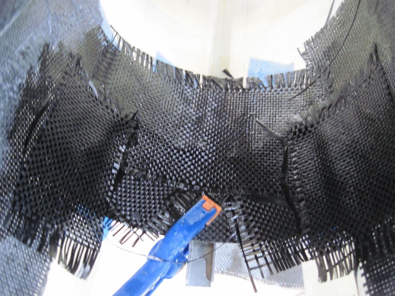
Belly extension.
To create the detailed belly I need to extend the bottom of the fuselage to the end of the wing.
I found a scrap piece of carbon fiber layup I made for the prototype of my P-47 that worked great.


I cut this to fit flush to the back cut out of the fuselage, and to keep the shape of the fuselage as it moves forward.
I taped a strait edge to the bottom center of the fuselage to keep my extension on the correct plan.
Some blue tape to seal the joint and get it ready to glass.


I am glassing the inside being the piece I installed already has a finish on it and it will just need some easy sand to clean up the joint.

I made a plywood mount so I could move over to the construction plane jig. This will be used throughout the build for construction, detailing and painting. It allows me to work on the plane with or without the cowl.
TB
To create the detailed belly I need to extend the bottom of the fuselage to the end of the wing.
I found a scrap piece of carbon fiber layup I made for the prototype of my P-47 that worked great.
I cut this to fit flush to the back cut out of the fuselage, and to keep the shape of the fuselage as it moves forward.
I taped a strait edge to the bottom center of the fuselage to keep my extension on the correct plan.
Some blue tape to seal the joint and get it ready to glass.
I am glassing the inside being the piece I installed already has a finish on it and it will just need some easy sand to clean up the joint.
I made a plywood mount so I could move over to the construction plane jig. This will be used throughout the build for construction, detailing and painting. It allows me to work on the plane with or without the cowl.
TB
 07-17-2014, 11:40 AM
#327
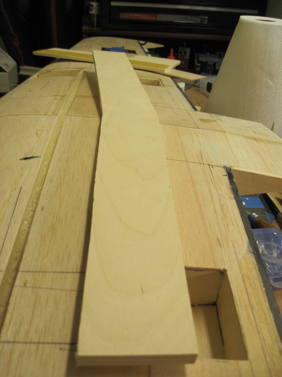
Main spar.
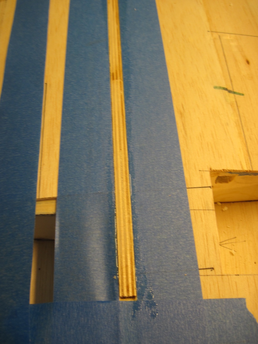
The main forward spar is cut into the wing from the bottom. I first cut a 1/4" trench then with sanding blocks I sand it to the 3/8" diameter.
A template is cut first out of some 3/32" balsa, then the spar is cut from 3/8" 7 ply birch.


after dry fitting the area is masked off with blue tape and the trench is filled with gorilla glue. A small brush spreads the glue to all the walls.
The spar is moistened with water to kick off the gorilla glue. within minuets the glue starts to foam out.
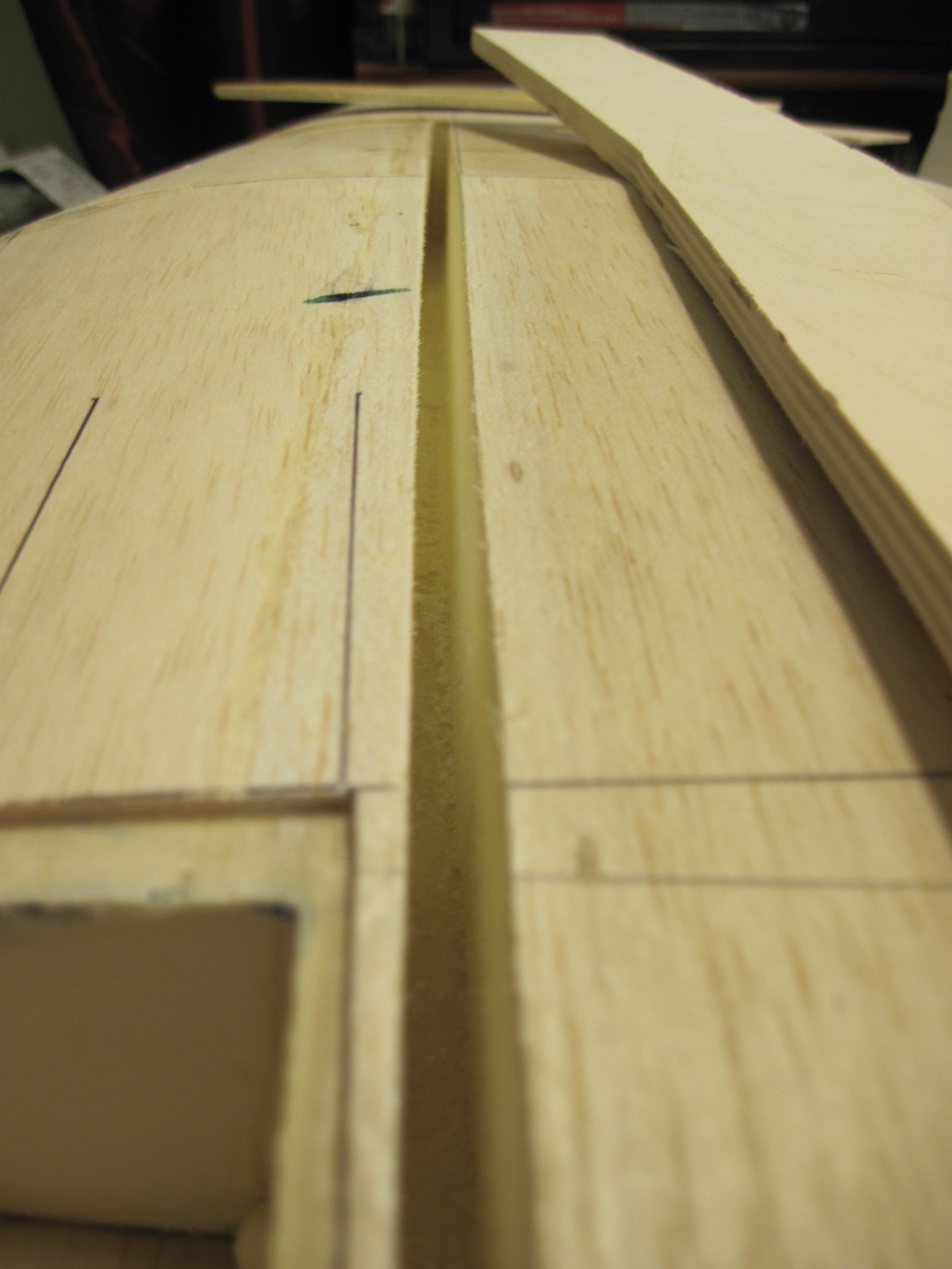
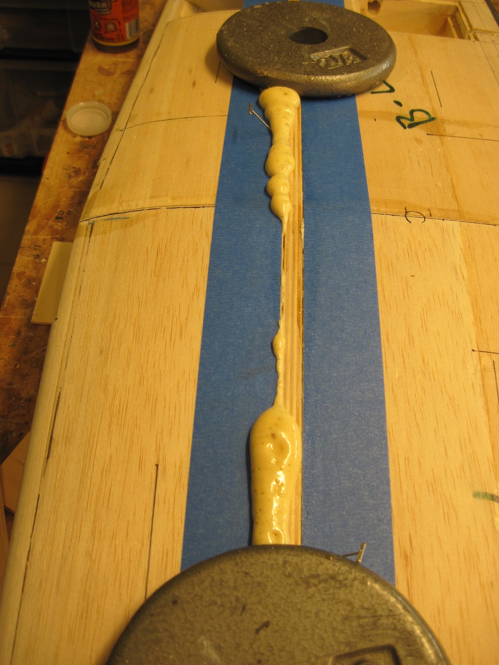
I will let this dry for a few hours before I sand it flush with the bottom of the wing.

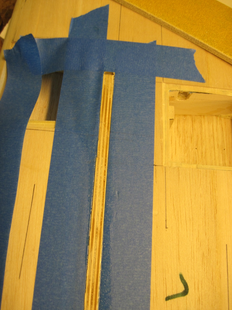
On to the rear spar.
TB
The main forward spar is cut into the wing from the bottom. I first cut a 1/4" trench then with sanding blocks I sand it to the 3/8" diameter.
A template is cut first out of some 3/32" balsa, then the spar is cut from 3/8" 7 ply birch.
after dry fitting the area is masked off with blue tape and the trench is filled with gorilla glue. A small brush spreads the glue to all the walls.
The spar is moistened with water to kick off the gorilla glue. within minuets the glue starts to foam out.
I will let this dry for a few hours before I sand it flush with the bottom of the wing.
On to the rear spar.
TB
07-17-2014, 01:24 PM
#328

Well as you usually do, you cover all the bases with detail and the usual good job. Hows your schedual regarding completion, will you fly it this summer, this was suppose to be a quick build so you could. Well there still is 3 months of fair to good weather ahead here, thats if an early Fall dosen't get us. I'm thinking an Indian summer would be great but I don't have much to say about that. Anyway I hope you get to fly it in the not too distant future.
Leroy
Leroy
07-17-2014, 05:07 PM
#330
Leroy, I have maybe 5 weeks into the build and after I get the wing mounted all I have left is the canopy. Yes it is a quick build, but I'm cursed with detail. I am working the next two months on it so should have it done before that.
Our flying season goes from June threw January or February, then the wind kicks in so I'm good.
TB
Our flying season goes from June threw January or February, then the wind kicks in so I'm good.
TB
07-17-2014, 08:05 PM
#331
Banned
That is not surprising. Typical shearing forces for some use in models is as follows.
Basswood ... the weakest ......... 370 psi
Birch ....................................... 600 to 1080
Pine ........................................ 600 to 1000
Maple ..................................... 740 to 1470
Hickory ................................. 1560 to 1980
The lowest 1/4 inch diameter dowel at 600 would typically shear at 29.45 lbs.
It is also possible that the material into which the dowel is inserted may itself fail.
Having said that, it is always wise to use two dowels inserted into hard plywood of sufficient thickness and the hole far enough from the edge ( birch ).
Zor
Last edited by Zor; 07-17-2014 at 08:09 PM.
07-18-2014, 02:59 AM
#333
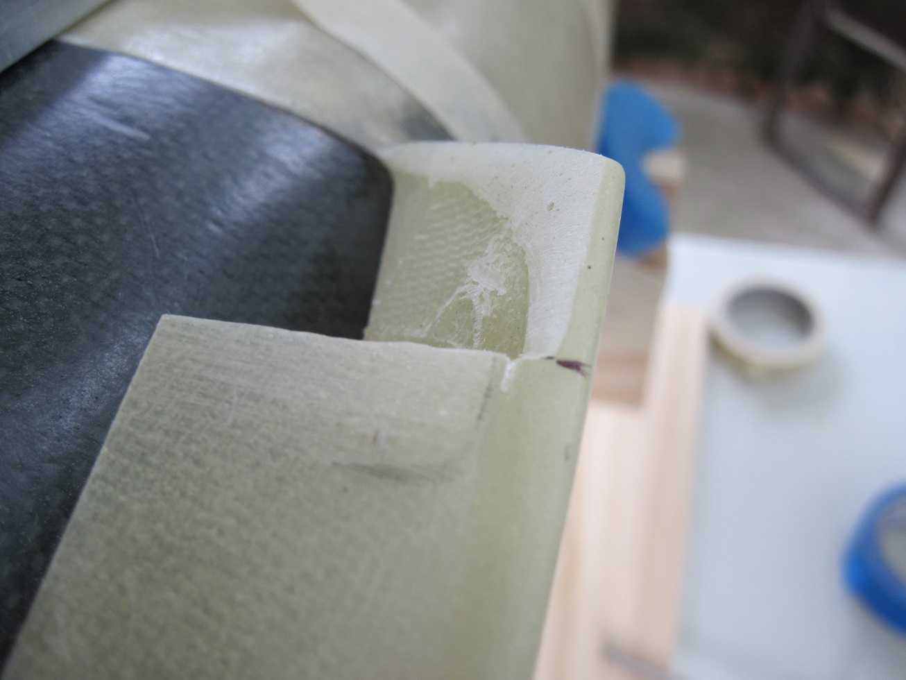
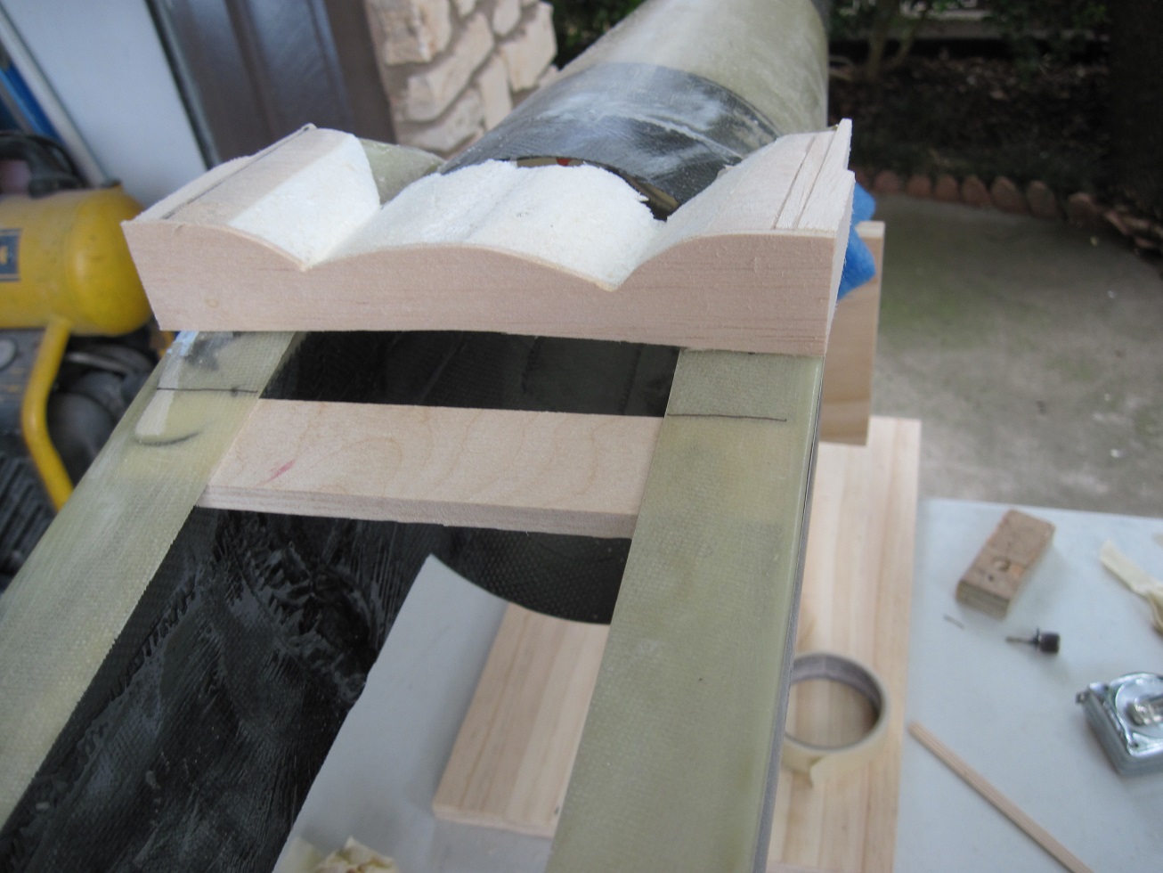
Wing belly.
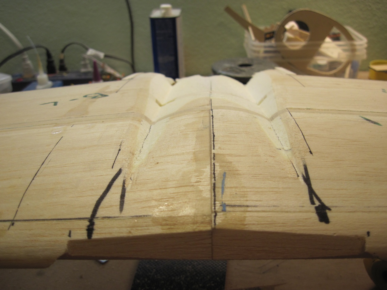
I started to shape the wing belly.
remember when I started to do the cowl and cutting the engine doors in, that dreadful feeling of "what have I done". Well I had that feeling once I started doing the wing belly. But as I got more into it and the shape started to form that feeling slowly went away, slowly!!
I have the rough shape and it looks ugly but it will clean up once I fit it to the wing.
I wont cut in the rear spar until I am closer. Then I can scribe it and there wont be a lot of sanding to do on it.
This area once I get it close will get glassed then I can finish it off with easy sand.
Been a rough few hours")


TB
I started to shape the wing belly.
remember when I started to do the cowl and cutting the engine doors in, that dreadful feeling of "what have I done". Well I had that feeling once I started doing the wing belly. But as I got more into it and the shape started to form that feeling slowly went away, slowly!!
I have the rough shape and it looks ugly but it will clean up once I fit it to the wing.
I wont cut in the rear spar until I am closer. Then I can scribe it and there wont be a lot of sanding to do on it.
This area once I get it close will get glassed then I can finish it off with easy sand.
Been a rough few hours
TB


 07-18-2014, 05:25 AM
#336

TB you are giving me ideas again! I have to replicate this wing to fuselage fit with a built up wing. A point in my favor the wing is constructed with a main and rear spar with slotted ribs so I think I see a may of pulling it off looking at your airplane.
Mike


Mike
Last edited by FlyerInOKC; 07-18-2014 at 05:36 AM.
07-18-2014, 05:38 AM
#338
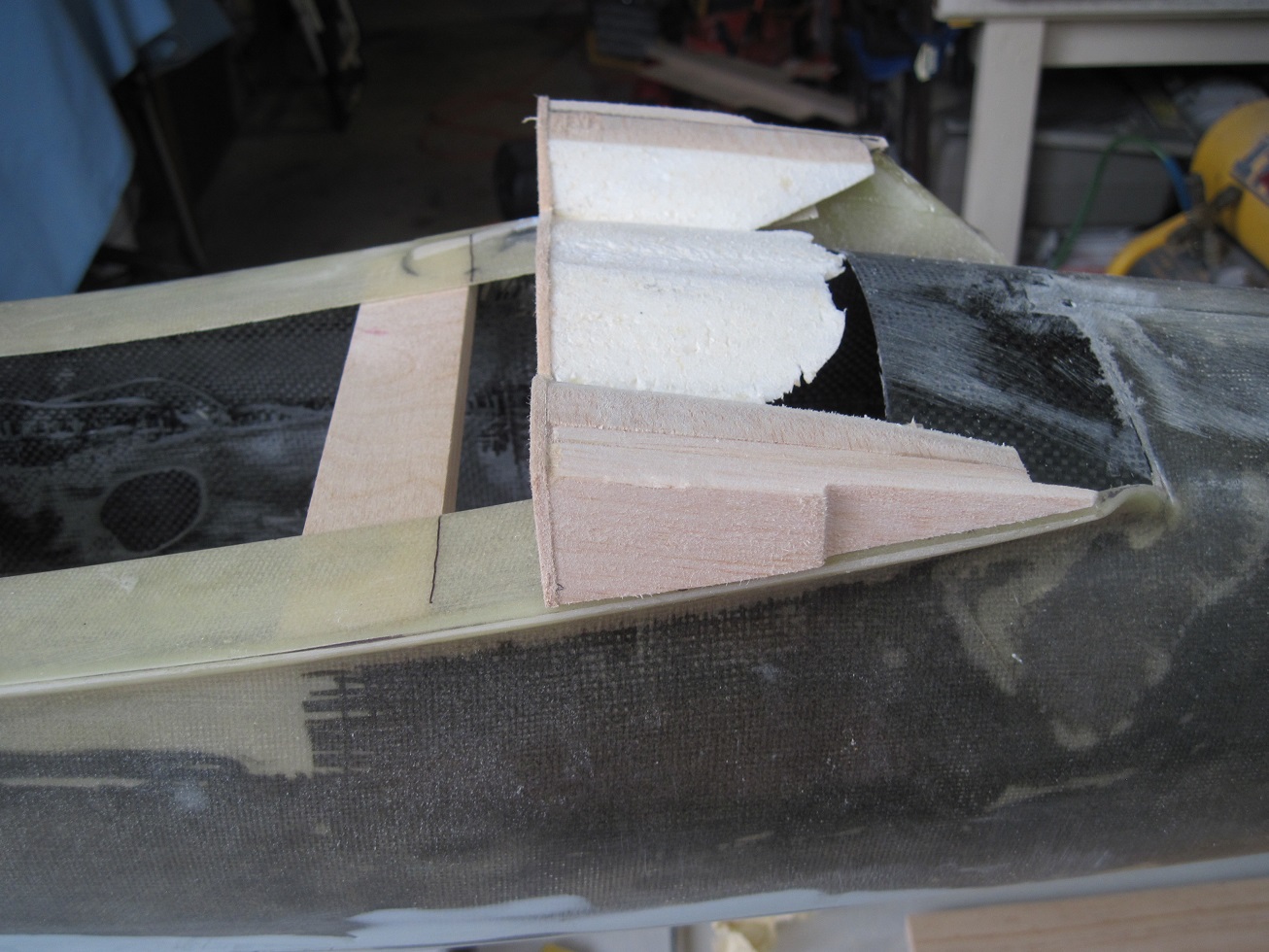
Rear spar.
Rear spar is installed and drying.
The spar is fabricated the same way as the main spar, 3/8" ply

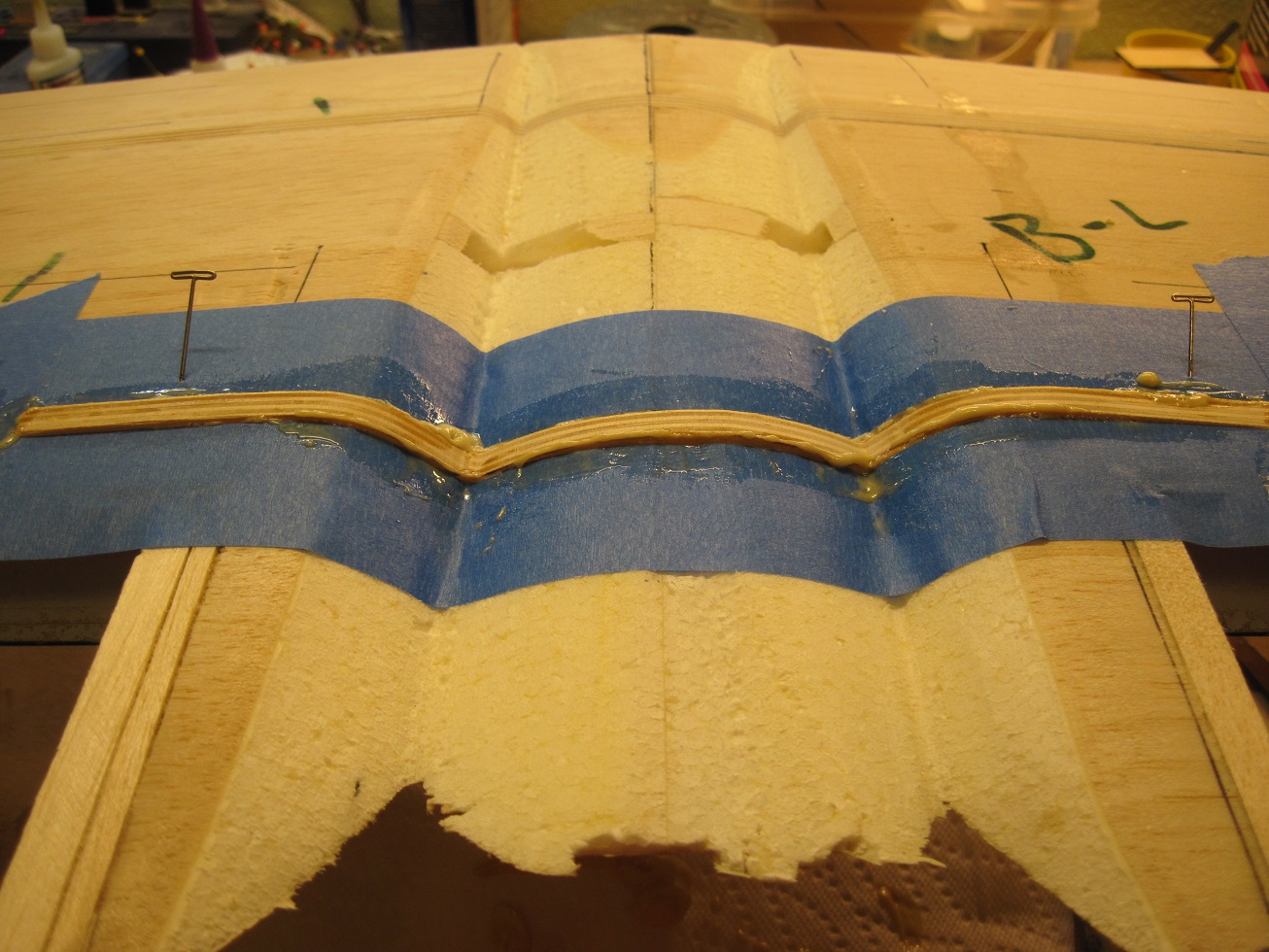
The rear spar will help keep the rear section strong and it will also have the wing bolts attached to it. Not sure if I will go in front or behind the spar.
I need to clear up the rear section and figure out how the connection to the rear fuselage and the rear of the wing will look like.
The wing dowels will be next and will go all the way back to the rear spar, hopefully
TB
Rear spar is installed and drying.
The spar is fabricated the same way as the main spar, 3/8" ply
The rear spar will help keep the rear section strong and it will also have the wing bolts attached to it. Not sure if I will go in front or behind the spar.
I need to clear up the rear section and figure out how the connection to the rear fuselage and the rear of the wing will look like.
The wing dowels will be next and will go all the way back to the rear spar, hopefully
TB
07-18-2014, 09:46 AM
#342
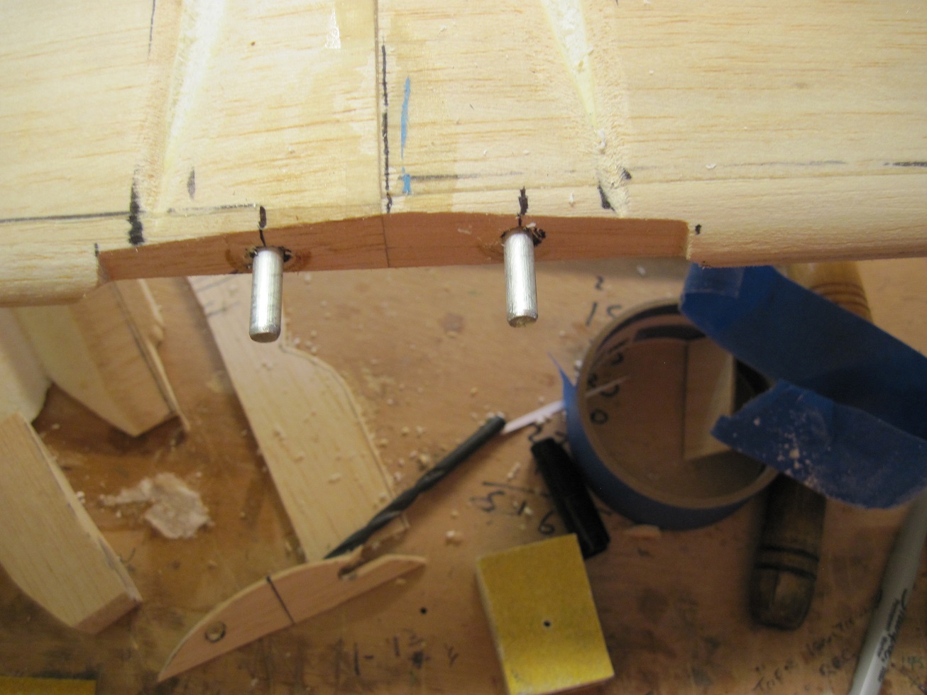
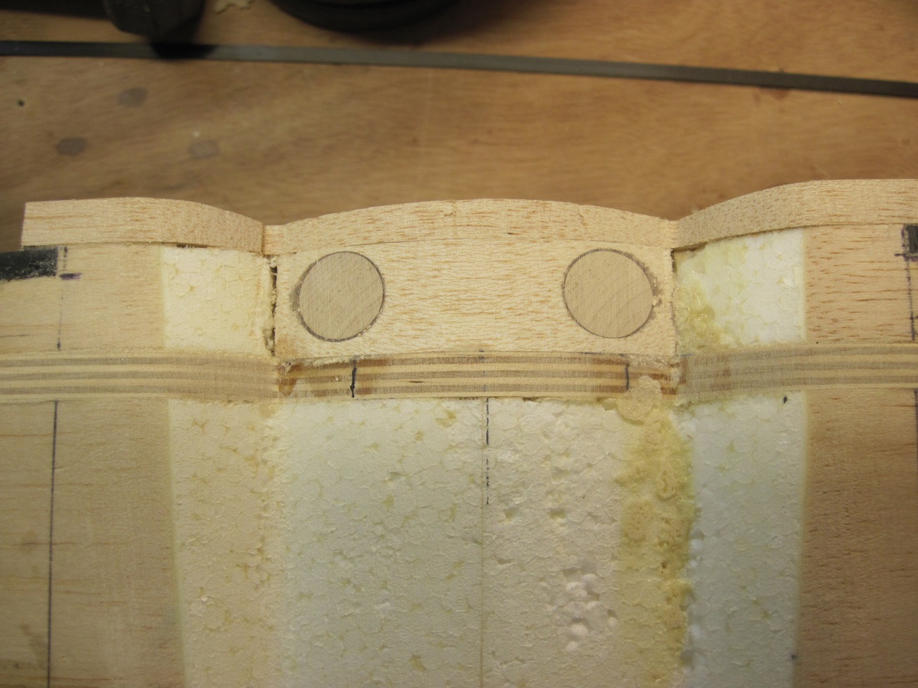
Wing dowels.
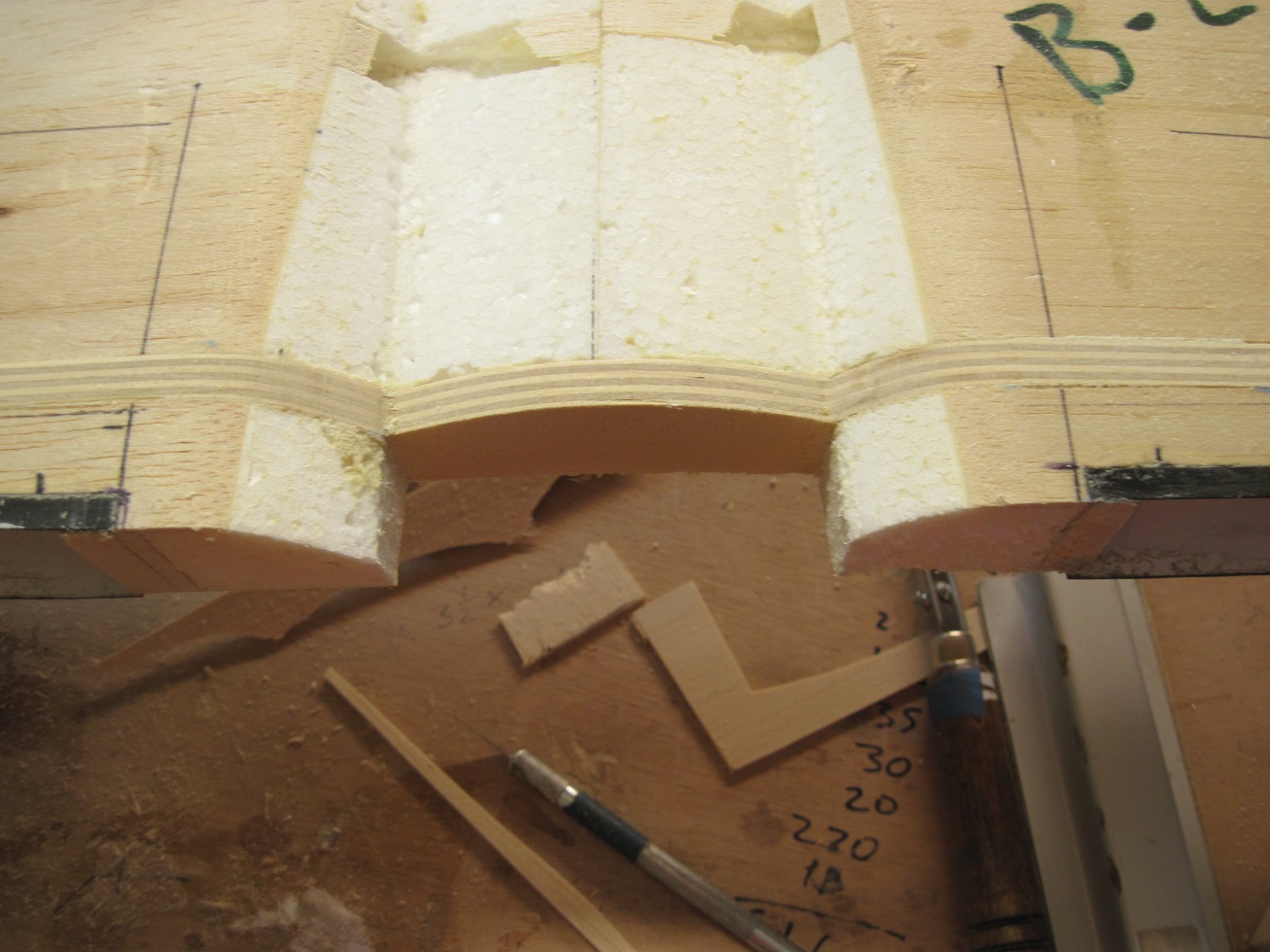
So the rear spar came out good.


I decided to cut the rear section of the wing belly off at the flap hinge line. It will work out much better to make that section part of the fuselage.
I faced it with some 3/32' balsa to hold it together during construction.


The wing bolt block will go right behind the rear spar.
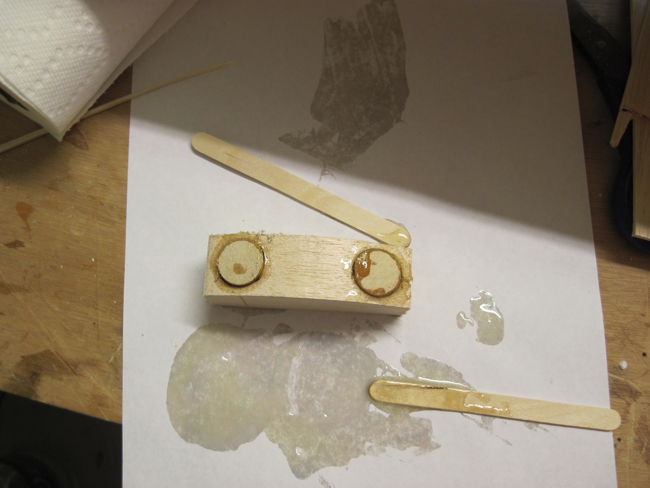
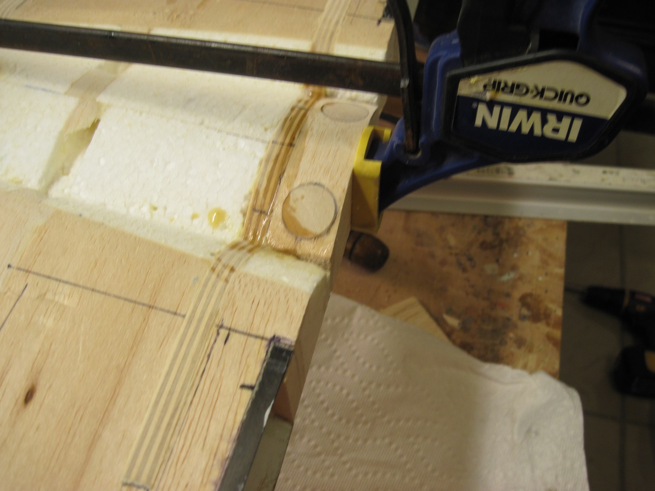
I used a piece of med density balsa and drilled two 3/4 " holes for some hard wood dowels.
Then I glued them in with epoxy.
The T-nuts will go into a piece of 3/8' ply that will be glued to the inside of the wing saddle.


Fitting the rear wing belly section to the fuselage will give me a much better finish, and it will be stronger this way.

I drilled the holes first in the fuselage for the wing dowels then mounted the wing held with tape and marked the holes with a sharpie from inside.
Two 1/4 aluminum dowels will go from front threw the main spar and into the rear spar.


I drilled them threw and got lucky, they both came out of the rear spar in good locations
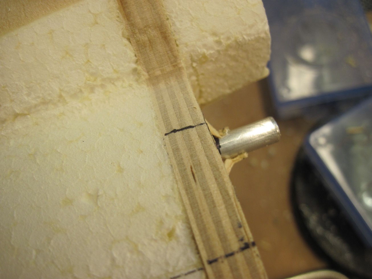
The wing fits great and I will add a piece of ply to the inside of the fuselage once the wing is all fitted and bolted.
The rear wing bolt block will sit right over the mounting ply.


I glued the dowels in with gorilla glue to fill all the voids in the foam from drilling, but mainly the dowels are in the front and rear spars.
The wing bolt block are glued with 30 min epoxy and once this sets I will pin it to the rear spar with two 1/4" dowels.

Moving right along.
TB
So the rear spar came out good.
I decided to cut the rear section of the wing belly off at the flap hinge line. It will work out much better to make that section part of the fuselage.
I faced it with some 3/32' balsa to hold it together during construction.
The wing bolt block will go right behind the rear spar.
I used a piece of med density balsa and drilled two 3/4 " holes for some hard wood dowels.
Then I glued them in with epoxy.
The T-nuts will go into a piece of 3/8' ply that will be glued to the inside of the wing saddle.
Fitting the rear wing belly section to the fuselage will give me a much better finish, and it will be stronger this way.
I drilled the holes first in the fuselage for the wing dowels then mounted the wing held with tape and marked the holes with a sharpie from inside.
Two 1/4 aluminum dowels will go from front threw the main spar and into the rear spar.
I drilled them threw and got lucky, they both came out of the rear spar in good locations
The wing fits great and I will add a piece of ply to the inside of the fuselage once the wing is all fitted and bolted.
The rear wing bolt block will sit right over the mounting ply.
I glued the dowels in with gorilla glue to fill all the voids in the foam from drilling, but mainly the dowels are in the front and rear spars.
The wing bolt block are glued with 30 min epoxy and once this sets I will pin it to the rear spar with two 1/4" dowels.
Moving right along.
TB
Last edited by TonyBuilder; 07-18-2014 at 09:49 AM.
07-19-2014, 02:09 AM
#345
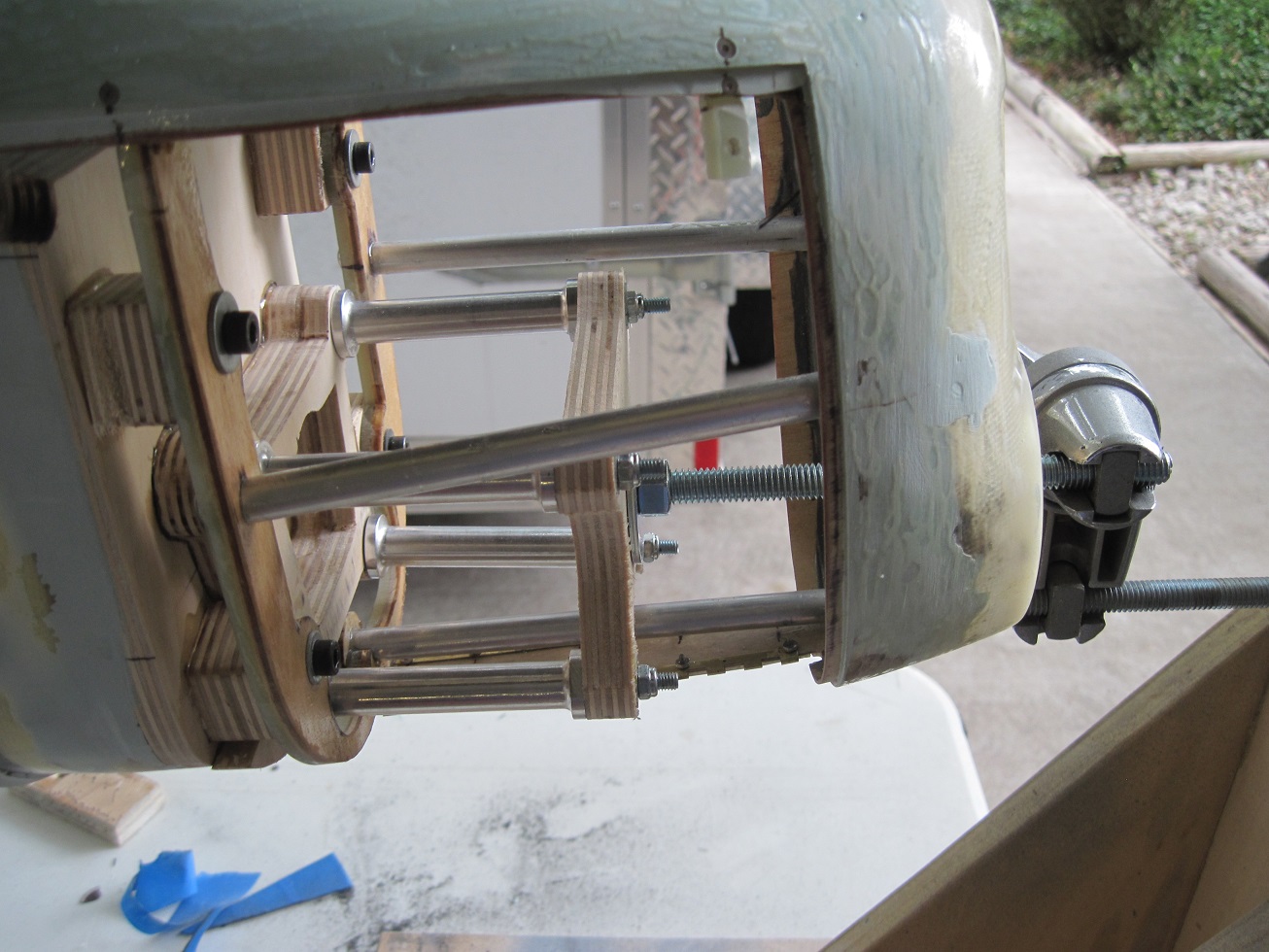
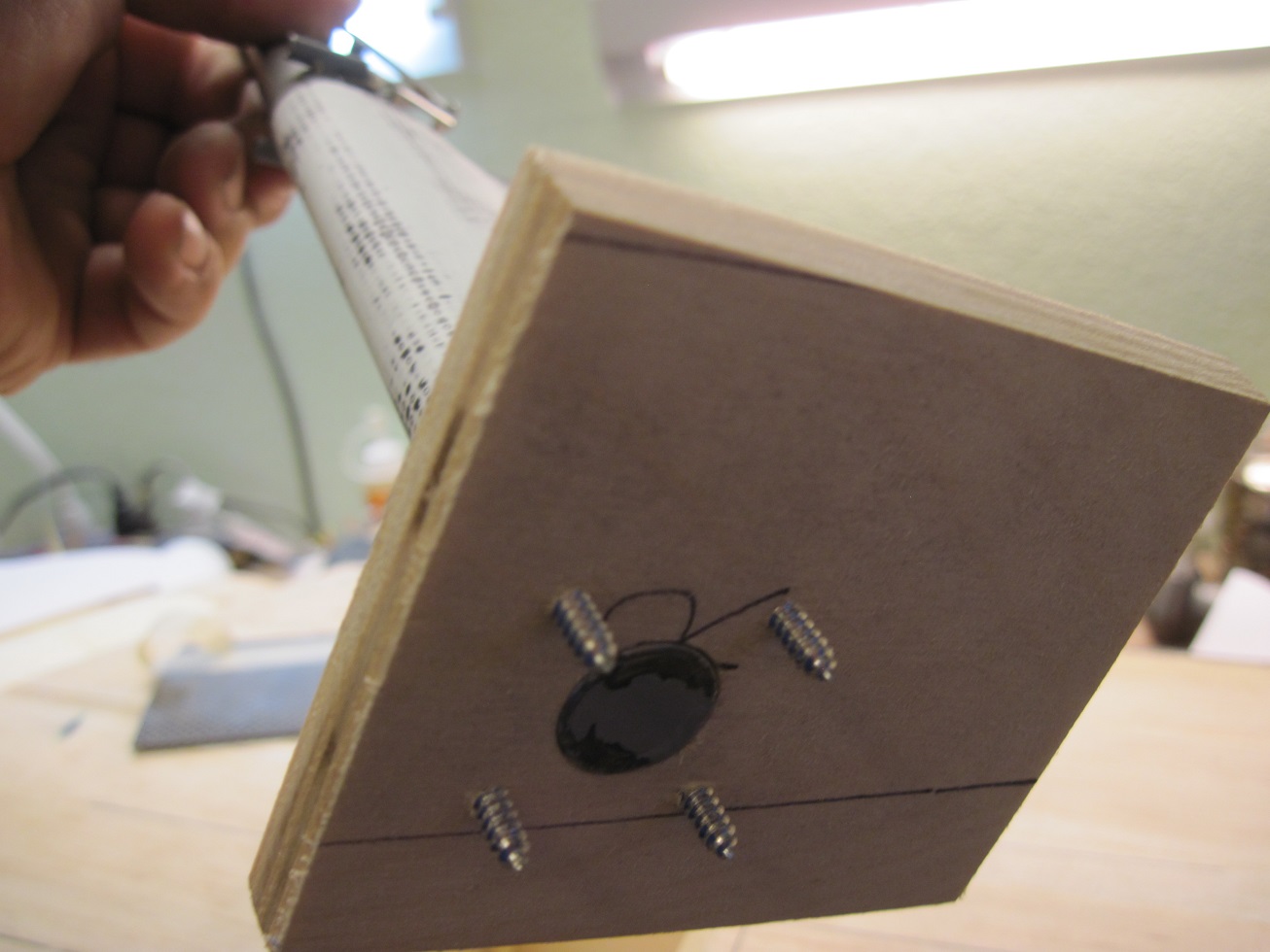
Now that the wing is done I will install the main gear so I can get her on her feet, plus I want to balance to see where I am at before I do the canopy.
I am getting ready to install the main gear blocks and the struts.
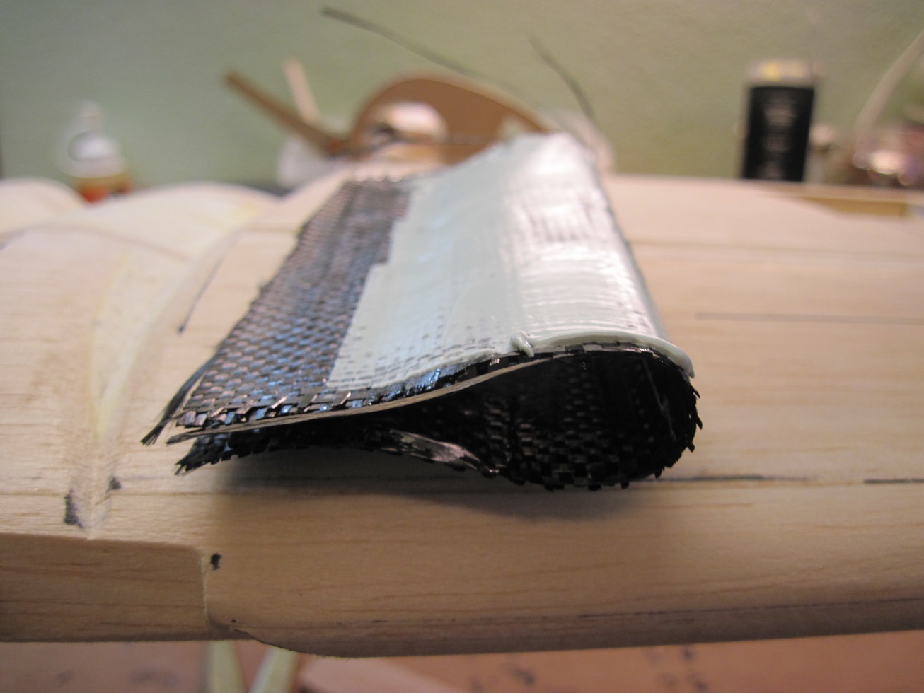
I made a mold and laid up the strut faring's. I want a removable fairing for maintenance and installation so some carbon fiber will do.


Some easy sand to finish it off.


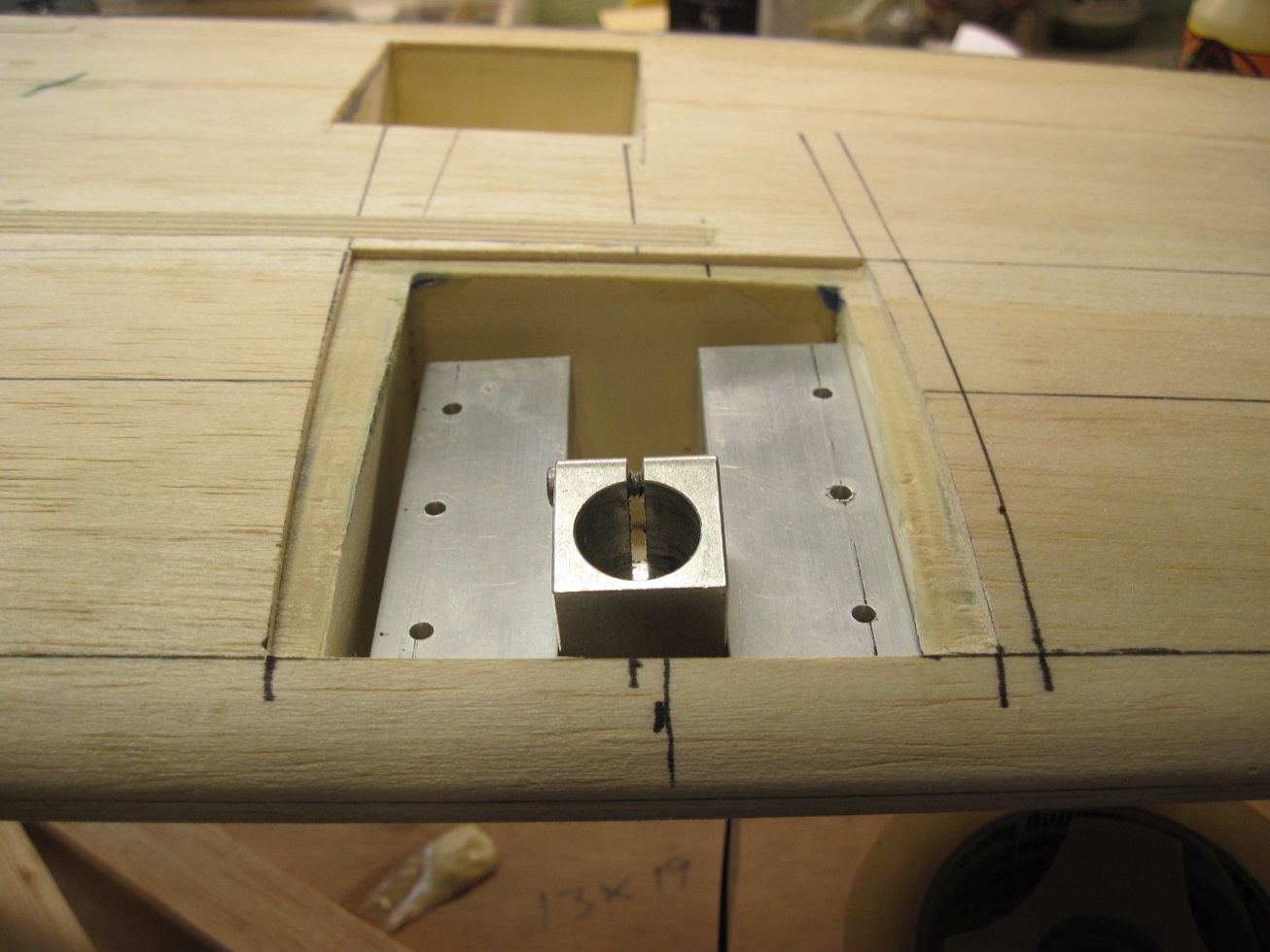
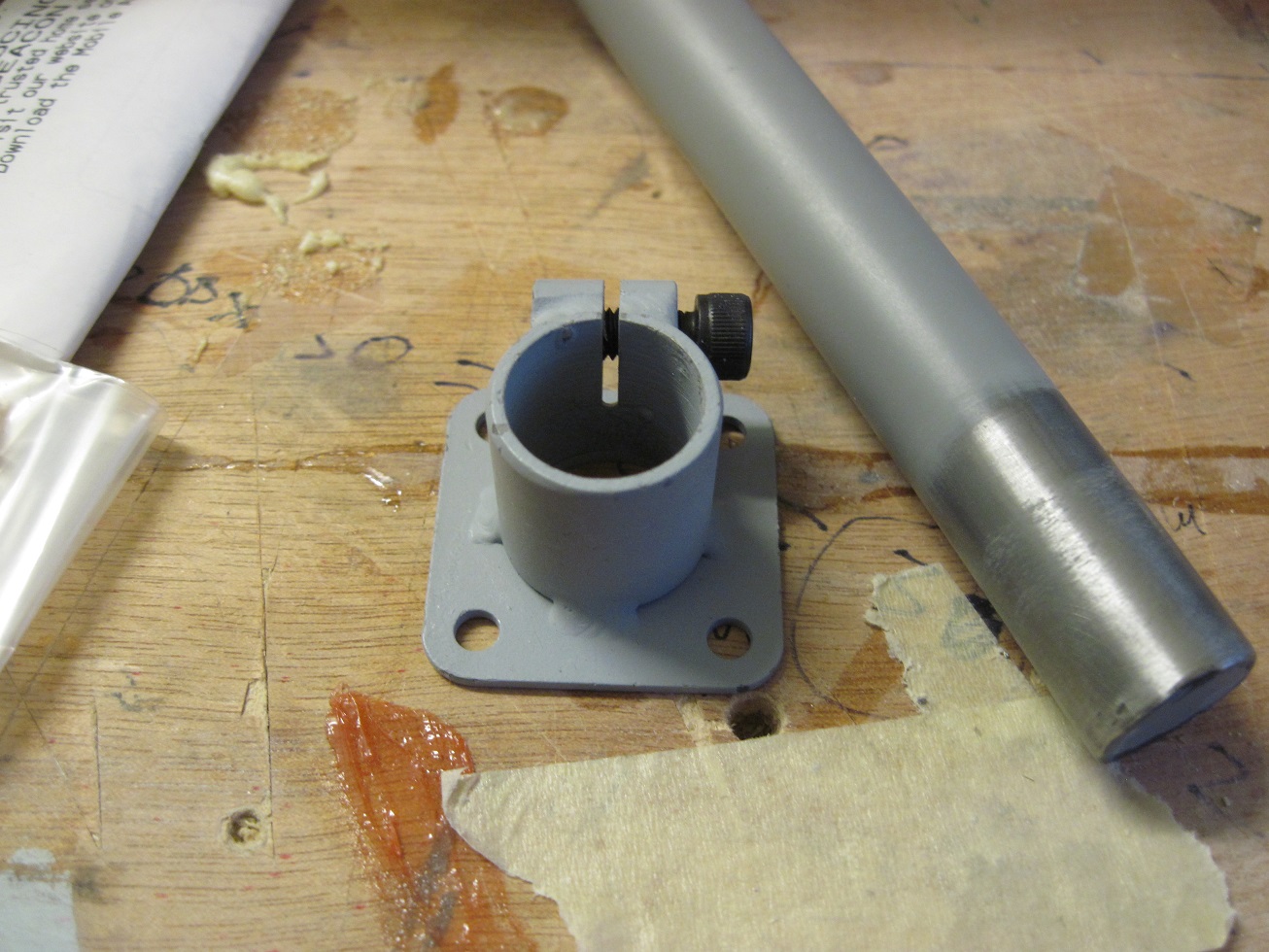
I will not be using the gear mounts I made, the trunion would stick out of the bottom of the wing, and I cant have that. So I will use the supplied mount.
The mount will sit on a ply deck, I will drill threw that and the mount will sit on top of that, should be easy.
The wing bolt blocks are ready to drill. I will be using steel bolts instead of plastic, as I do on all my planes.
TB
I am getting ready to install the main gear blocks and the struts.
I made a mold and laid up the strut faring's. I want a removable fairing for maintenance and installation so some carbon fiber will do.
Some easy sand to finish it off.
I will not be using the gear mounts I made, the trunion would stick out of the bottom of the wing, and I cant have that. So I will use the supplied mount.
The mount will sit on a ply deck, I will drill threw that and the mount will sit on top of that, should be easy.
The wing bolt blocks are ready to drill. I will be using steel bolts instead of plastic, as I do on all my planes.
TB
07-19-2014, 02:15 AM
#346
On the bench for today will be the main gear mounts, bolt the wing, and install flaps, ailerons, and the servos. That should finish the wing and then its glass time. But first some morning fly time, need to get some more time on the DLE55
TB
TB
07-19-2014, 05:21 AM
#347
Strut fairings.
The main gear block on the right wing is cut and the gear installed. I will most likely glue in side rails with ply and then bolt the gear mount plate to that so I can remove it and if I do have a mishap hopefully the block will break loos and not tear the wing mounts out.


The strut fairing is trimmed and I will be cut to size once I determine strut length.
Scale length is 6" from axle center to bottom of wing. I need to make sure I have plenty of prop clearance with the 22-23" props. Planed prop will be a 22x10 Xoar.

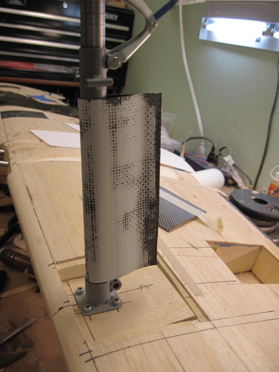

Top of the fairing gets a piece of 1/8" balsa to form the top, this is glued in with CA and is only a plug. A piece of carbon laminate will finish out the bottom of the strut fairing.
The top gets one too once I cut it to length.


The strut fairing will be secured with a bracket and two screws.


TB
The main gear block on the right wing is cut and the gear installed. I will most likely glue in side rails with ply and then bolt the gear mount plate to that so I can remove it and if I do have a mishap hopefully the block will break loos and not tear the wing mounts out.
The strut fairing is trimmed and I will be cut to size once I determine strut length.
Scale length is 6" from axle center to bottom of wing. I need to make sure I have plenty of prop clearance with the 22-23" props. Planed prop will be a 22x10 Xoar.
Top of the fairing gets a piece of 1/8" balsa to form the top, this is glued in with CA and is only a plug. A piece of carbon laminate will finish out the bottom of the strut fairing.
The top gets one too once I cut it to length.
The strut fairing will be secured with a bracket and two screws.
TB
Last edited by TonyBuilder; 07-19-2014 at 09:06 AM.