


1/6 F-105 Build Thread

 10-25-2018, 05:47 PM
#128

Thread Starter
My Feedback: (20)
Butch sent me his drawings for the stab system he drew. He says he will send me the stab drawings also.
I was wanting to simplify it and make the stabs removable for transport. Something like the Skymaster for BVM 1/5 F-16 system. Not sure where we can get some hardware like that.
Gary
I was wanting to simplify it and make the stabs removable for transport. Something like the Skymaster for BVM 1/5 F-16 system. Not sure where we can get some hardware like that.
Gary
10-26-2018, 03:25 AM
#129

This is an interesting build thread. It should provide a great resource for others out there with the same project. Since I'm interested in aerodynamics, I read thru the section on the stab pivot location and airfoil with interest, and even did a few calculations of my own. The aerodynamic center of this F105's current tail airfoil is at 26% MAC, so whoever came up with 25% at the AMA had a good guess. Maybe lucky, as they had no way of knowing which airfoil any given jet would have. My numbers basically confirm there is a problem here unfortunately. The pivot is definitely too far forward, and the problem is that it probably won't flutter (no guarantees at high speed) but its current location puts a huge load on the servos since there is nothing close to aerodynamic balance. All the load is aft of the pivot. The pencil diagram in the earlier post shows the 25% MAC a bit too far forward from what I found, but my results only further reinforce the idea there's a problem. Also, I found the current pivot is almost at 0% MAC, way too far forward. I don't know why the difference in my numbers, and it's not important. A gentle suggestion is to carefully question the plan going forward, before going through all that work to create a whole new stab. First, the new stab is thinner, thus not as stiff. Why do that when the original worry is flutter? Also, the proposed new shaft of 1/2" is overdesigned and doesn't leave enough web between the ribs and the skin. Someone else here also brought that up. The original stab airfoil probably won't blank at lower speeds because it's thicker, something a pilot landing this beautiful bird might appreciate. It should be quite doable to simply use a centerpoint drill to cleanly cut a new pivot shaft location in the original STAB somewhere around 2" or 2-1/8" aft of the current version. I don't recommend using a standard drill point as the ribs will just splinter. Use the current pivot pin as a straightness guide to make a suitable wooden fixture to hold the stabs for the drilling. I'm envisioning some kind of angle plate hung off the side of a drill press table. Maybe go with 7/16" diameter instead of 1/2", to preserve some rib web thickness. Now I'll duck. 
10-26-2018, 07:42 AM
#130
Thread Starter
My Feedback: (20)
Pull Up, Awesome post. You are giving me hope we can use the existing stabs and I could modify them myself. I had thought of that before but the airfoil was the question and generated the need to replace the stabs. I agree the existing pivot point is wrong but that can be changed.
If I understand your post correctly you are saying the existing airfoil would work. I don't think it would be a problem on an RC jet model but I have some questions.
What do you mean by the "aerodynamic center at 26% MAC"?
If the pivot was moved back 2-2 1/8" what MAC what % MAC would the pivot be?
Why does AMA want the pivot forward of 25% MAC?
What do you mean by "original stab airfoil probably won't blank at lower speeds because it's thicker, something a pilot landing...might appreciate"?
Why would one want to use a NACA 0009 instead of the existing airfoil?
I'm at the SC Tiger Jet Meet now and a friend says he can X-ray the current stab to find out the insides and where to put the cross rod. That would make it easier to modify. Also he can machine a servo drive pocket to put in the root end similar to the SM or BVM F-16 servo drives.
Maybe this can work and save the time and effort (and $$$) of making a new stab. Thanks for your help and interest.
Gary
10-26-2018, 08:52 AM
#131
Hi Gary, thanks for your comments. I'll try to answer your questions in order.
1. Every lifting surface has a mathematical point thru which all aerodynamic forces are "centered". Even irregular surfaces. The best analogy is center of gravity. Every irregularly shaped mass has one point thru which gravity is exerted. In this F105 tail plane, I calculated that point is around 8.47" aft of the leading tip at the fuse. Your diagram was a bit forward of that, I'm not sure why. No big deal.
2. If the pivot is moved back 2.23" from it's current location, it would be at 22% MAC, or 4% forward of the MAC. This difference is consistent with known practices, including the AMA guide
3. Not just the AMA, but established practices and even common sense puts the greater drag behind the pivot. Having the pivot behind the major aero forces can cause runaway loads on the control system.
4. This one is simple, a thicker airfoil has higher lift, even if it's in the down direction as is the case with a stab. An elevator can stall on it's own, or it may be blanked out by disturbed air from some part of the jet in front. As the jet slows, a slightly thicker stab could possibly have a better chance holding the nose up to land on the mains, for a given amount of travel. I'm not sure if the difference would be noticeable or not, but it does no harm and saves time, labor, and money. The main hit is drag, but you're not going supersonic and fuel range isn't the issue with RC. Just some thoughts, others might disagree.
5. Why an NACA 0009? I can't think of an overriding reason. RC planes don't scale well aerodynamically compared with full scale planes, thus many RC industry leaders modify airfoils. Leave the exact scale efforts for weathering and rivets.
Hope all this helps to add some perspective.
10-26-2018, 01:39 PM
#132

Well I would want the pivot a bit too far forward than too far back. In fact, I flew a plane with it too far back and the porpoising at 180 mph was one of the wildest rides I ever had. I think I had to move the pivot forward just under 3/4 inch to cure it.
But I moved the pivot in the fuselage (to keep the stab aligned with the root fairings) and the manufacturer made me new stabs.
As for reworking stabs, you can do it, but you cant put the antirotation pin in through the root hole (or at least I cant visualize how to do it) you will need to cut into the skin . At that point, I say it is just as easy (and lighter) to build new stabs. But that is just me. And the main loads are carried though the skins so if you have proper skins and reinforcements like CF, in my experience the stab shaft can come right up and touch the internal skins no problem. They are glued in to within an inch of their life in any case!
10-26-2018, 05:19 PM
#133
Well, who knows, Mr Matt....the 3/4" you moved your pivot might have placed it 4% ahead of the MAC. I just can't believe you're equating the work to create two entirely new stabs with that of filling a couple little anti-rotation pin holes. Besides, there is a way for installing anti rotation pins without disturbing the skin at all.
10-26-2018, 05:33 PM
#134
Thread Starter
My Feedback: (20)
I think I understand the aerodynamic center to be what I was calling the center of pressure and that would have to be some distance aft of the pivot point to function properly. I just don't have any knowledge of how far aft other than the AMA guidelines and what Pull Up describes as "known practices" which is good enough for me. I probably am over thinking this too much as it should be pretty easy to pick a spot and drill the hole.
I think I could replace the pivot shaft more easily than rebuild the stabs. I was thinking of making cuts into the bottom skin to install the anti rotation pin after finding out where the internal structure was from X-ray photos. It should be small cuts and easy to reinforce after the anti rotation pin was installed and securely glued in.
I still have to figure out a way to retain the stab pin inside the fuse and to actuate the stab with the servo.
How would you install the anti rotation pin with out cutting into the skin at all?
Last edited by Viper1GJ; 10-26-2018 at 05:42 PM.
10-27-2018, 07:50 AM
#135
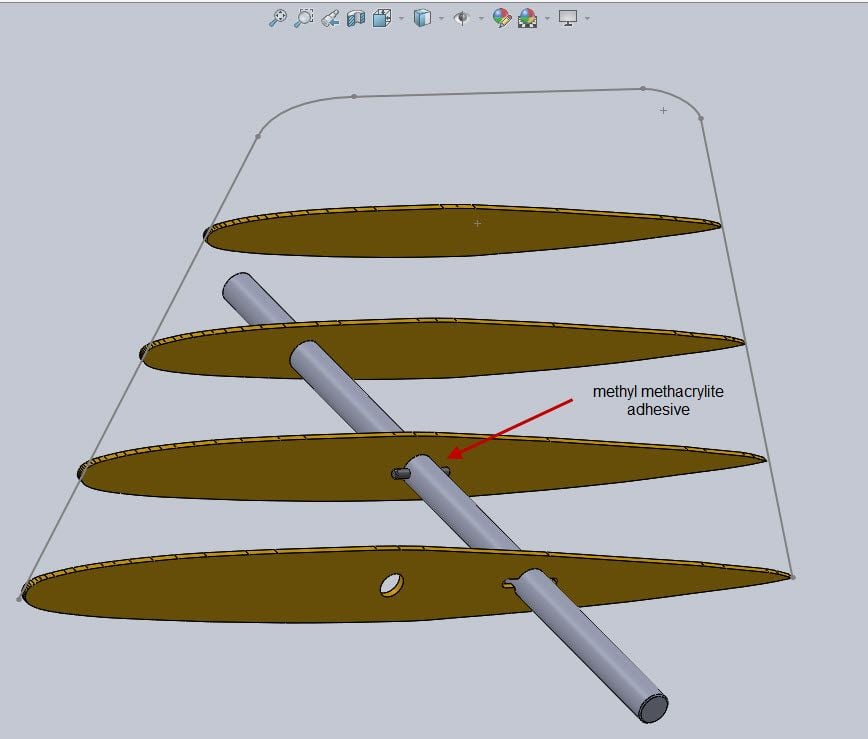
Install a spring pin in the pivot shaft, and cut a keyhole in the root rib for it to pass by. Drip methyl methacrylate epoxy thru the root rib, allowing it to pool around the hole in the 2nd rib. Of course, coat the shaft with the same adhesive before the final assembly. Then glue up the keyhole slot too.
10-27-2018, 05:25 PM
#136
10-27-2018, 07:32 PM
#137
Gary, methyl methacrylate is available from Express Composites, and I also saw it on Amazon. But I'm not sure of the price from Amazon, as lately their pricing has been all over the map, high and low. I've personally had a lot of hysol separate from inner fiberglass walls surprisingly clean. I know it's been recommended for fiberglass models for years, but around here we've had better luck with MM. It's slightly more pliable, yet sticks to fiberglass much better. If you've ever dimpled your glass fuse from picking up the jet and heard that popping sound of the formers coming loose, that's what this stuff prevents. I don't know about West Systems. I know you used hysol everywhere, but don't panic. Your plane will be fine. You could just go over some of the joints with MM if you wish, or just leave it as is.
10-29-2018, 06:13 PM
#139
Thread Starter
My Feedback: (20)
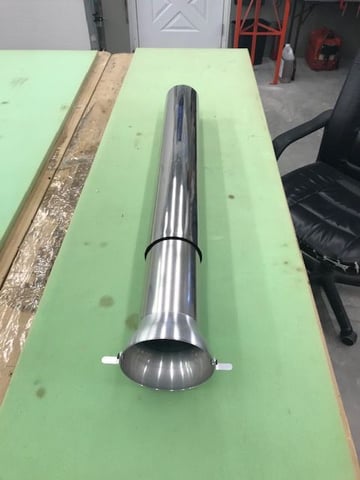
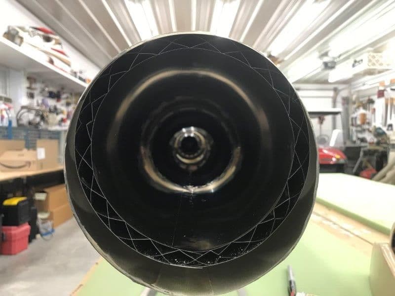
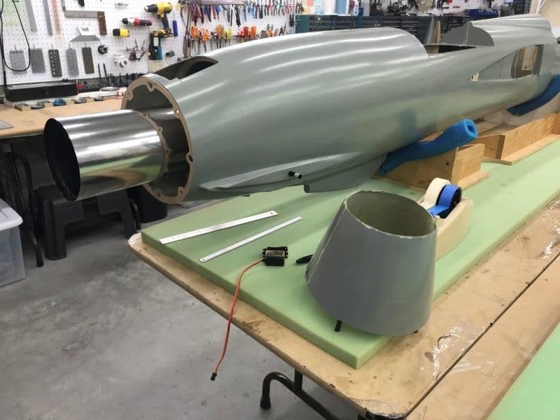
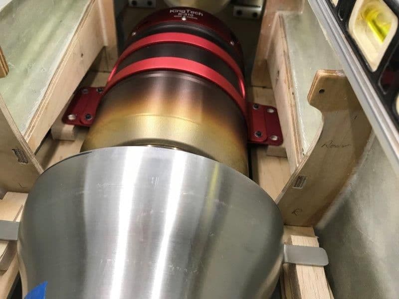
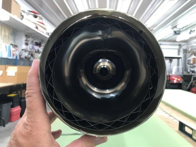
The big brown truck dropped off a long box today. I opened it up and out pops a cool looking custom pipe from Joey Tamez at J.E.T Pipes in Ft. Worth, TX. It looks great, very high quality.
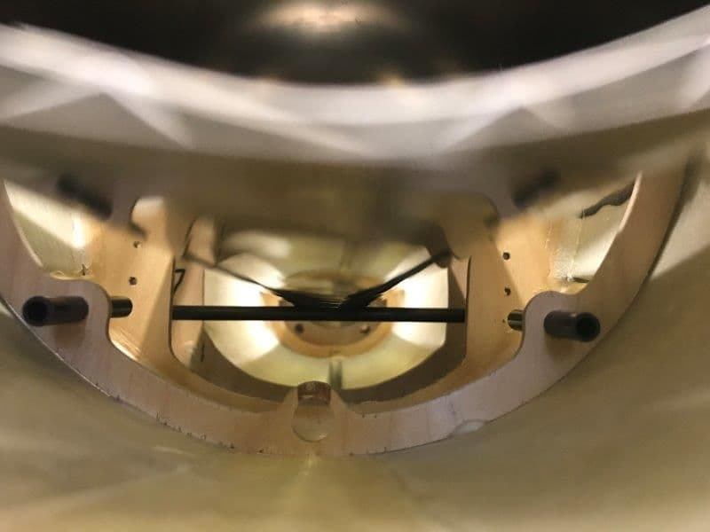
Joey made the pipe from a drawing I sent him. It has an extra internal zig zag support ring about 6" from the aft end where the aft bulkhead will support it. This will keep the outer tube from crushing into the inside tube as I have seen happen before. I will try to get it installed soon.
Joey made the pipe from a drawing I sent him. It has an extra internal zig zag support ring about 6" from the aft end where the aft bulkhead will support it. This will keep the outer tube from crushing into the inside tube as I have seen happen before. I will try to get it installed soon.
 10-30-2018, 05:40 AM
#141

Install a spring pin in the pivot shaft, and cut a keyhole in the root rib for it to pass by. Drip methyl methacrylate epoxy thru the root rib, allowing it to pool around the hole in the 2nd rib. Of course, coat the shaft with the same adhesive before the final assembly. Then glue up the keyhole slot too.
10-30-2018, 11:22 AM
#142
Hi Gary, sorry it took so long to answer. I have not used this particular technique, but I would not hesitate to do so. Fiberglass skin is pretty thin too, so I'm not sure pinning thru the skin is really any better.
To ensure a great fillet of glue,, apply it freely to the pin and shaft prior to insertion. Secondly, and most important, use a long wood skewer with a little flat "shovel" sanded onto the end to reach down to the 2nd rib and repeatedly scrape globs of MMA glue onto the rib right at the hole. You can use the rib itself as the edge to scrape against to transfer the glue from the "shovel" to the rib. Do this all around the circumference repeatedly to build up a bunch of glue. The glue is pretty thick so it's not going to run around like 5 min epoxy does. Nonetheless, while it's drying, alternate holding the rib up in the air, then the other way, to keep a fillet clung to the aluminum. Don't hold it horizontal, in other words. And I forgot one more piece of insurance. If you happen to use 1/2" aluminum instead of 3/8", you can add a 2nd spring pin to engage in the keyhole slot in rib #1, giving you twice the torque resistance. Also, use a flashlight to peek down the hole to inspect the glue fillet on rib#2 just before the spar goes in. That's just to make sure the glue is where it should be. Add more quickly if more is needed. For the 2nd spring pin by the root rib, I probably wouldn't do that for any diameter under 1/2" because drilling the cross hole weakens the spar just at the wrong spot. 1/2" should be fine though.
To ensure a great fillet of glue,, apply it freely to the pin and shaft prior to insertion. Secondly, and most important, use a long wood skewer with a little flat "shovel" sanded onto the end to reach down to the 2nd rib and repeatedly scrape globs of MMA glue onto the rib right at the hole. You can use the rib itself as the edge to scrape against to transfer the glue from the "shovel" to the rib. Do this all around the circumference repeatedly to build up a bunch of glue. The glue is pretty thick so it's not going to run around like 5 min epoxy does. Nonetheless, while it's drying, alternate holding the rib up in the air, then the other way, to keep a fillet clung to the aluminum. Don't hold it horizontal, in other words. And I forgot one more piece of insurance. If you happen to use 1/2" aluminum instead of 3/8", you can add a 2nd spring pin to engage in the keyhole slot in rib #1, giving you twice the torque resistance. Also, use a flashlight to peek down the hole to inspect the glue fillet on rib#2 just before the spar goes in. That's just to make sure the glue is where it should be. Add more quickly if more is needed. For the 2nd spring pin by the root rib, I probably wouldn't do that for any diameter under 1/2" because drilling the cross hole weakens the spar just at the wrong spot. 1/2" should be fine though.
10-30-2018, 02:57 PM
#143
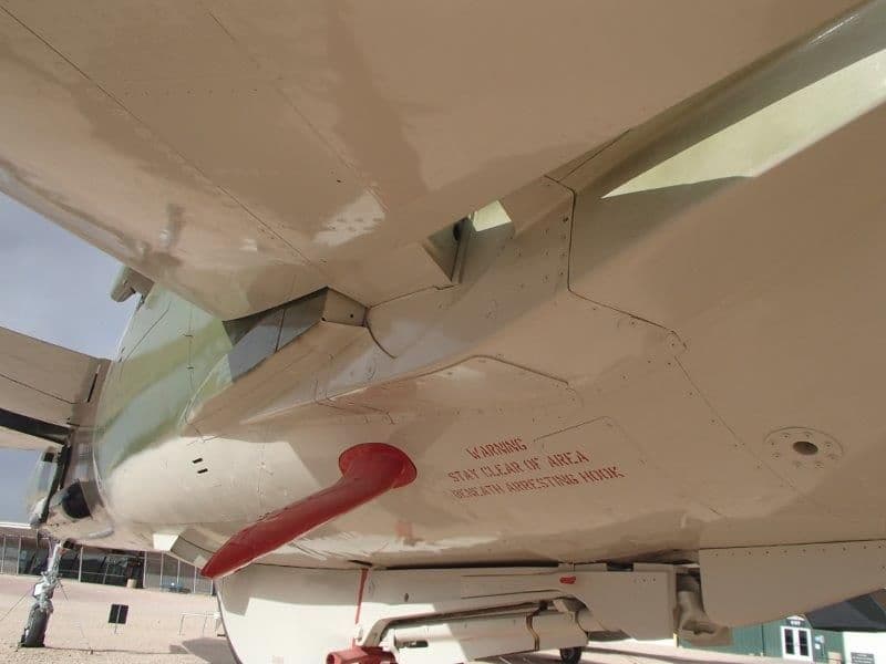
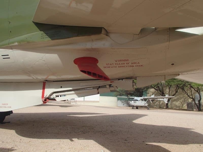
Talked to Butch last night.......to clarify my earlier post, the real jet used the trapeze system for one reason...........to counter-act flutter! Having seen the tail section at Meacham Field in Ft. Worth,It was evident the stab mounting was spread to 2 mounting points on each side of the pivot points. In other words , each stab was bolted to these mounting plates. I'm not an engineer , but common sense tells me that 2 mounting points OUTSIDE of the pivot would be immensely better than a single pin inside the stab. Also, this allows for very little push -pull movement translating into a much larger movement for the stabs themselves.
The great Lynn McCauley always told us..."if it worked on the real one, you better use it on the model".......I think you really ought to look into this rather than lose this magnificent model due to stab failure.
Just my 10 cents........
The great Lynn McCauley always told us..."if it worked on the real one, you better use it on the model".......I think you really ought to look into this rather than lose this magnificent model due to stab failure.
Just my 10 cents........
10-30-2018, 04:06 PM
#144
Thread Starter
My Feedback: (20)
Thanks for the inputs. I can use all the help I can get.
Here is the drawing Butch provided Larry and myself. The stab mounts that came with the kit parts had a pendulum mount but they were unusable from binding and different sizes.
I started today looking to see if I can get a production stab mount system that would have plug in stabs removable for transport. I'm checking with BVM now to see if the units used on the 1/5 F-16 can be purchased separately as parts. Also looking at other sources.
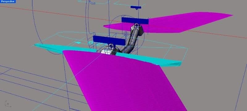
When I saw the drawings I thought of the mass and strength of the cross trapeze system to prevent flutter and also to allow dual hydraulic systems to attach to both stabs as there was no differential that I am aware of. Also the cross beam allows both stabs to be connected and pivot together without a cross member going through the engine.
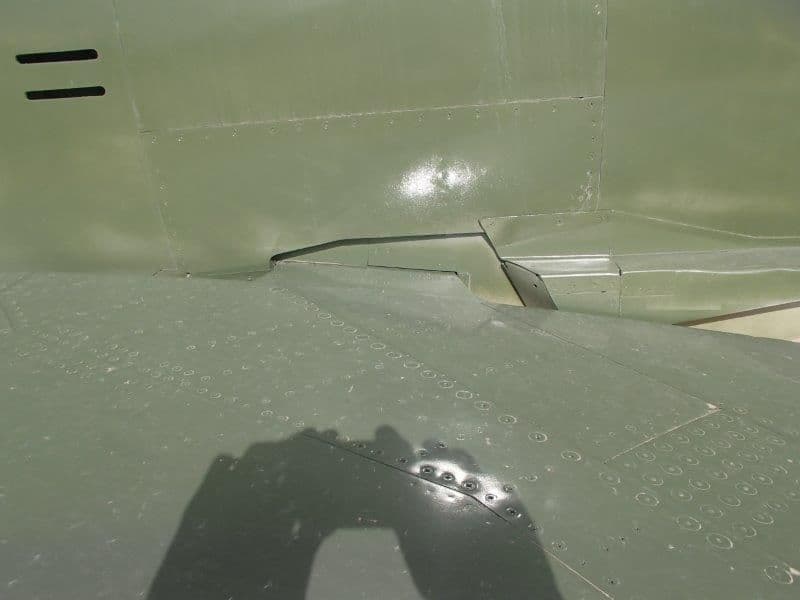
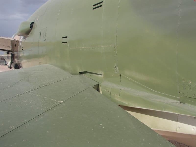
Full scale photos.
Here is the drawing Butch provided Larry and myself. The stab mounts that came with the kit parts had a pendulum mount but they were unusable from binding and different sizes.
I started today looking to see if I can get a production stab mount system that would have plug in stabs removable for transport. I'm checking with BVM now to see if the units used on the 1/5 F-16 can be purchased separately as parts. Also looking at other sources.
When I saw the drawings I thought of the mass and strength of the cross trapeze system to prevent flutter and also to allow dual hydraulic systems to attach to both stabs as there was no differential that I am aware of. Also the cross beam allows both stabs to be connected and pivot together without a cross member going through the engine.
Full scale photos.
Last edited by Viper1GJ; 10-30-2018 at 05:41 PM.
10-30-2018, 04:40 PM
#145
Thread Starter
My Feedback: (20)
Gary
10-30-2018, 05:02 PM
#146
Thread Starter
My Feedback: (20)
As mentioned above I got the pipe delivered this week. Joey did a great job making the pipe.
I made the first dry fit to determine if it fits and how to mount the aft end.
I made the first dry fit to determine if it fits and how to mount the aft end.
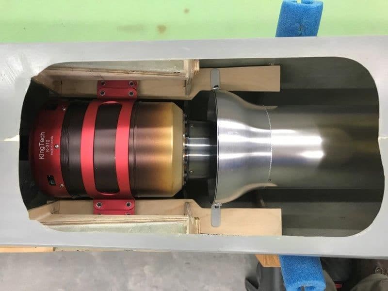
The front end fits exactly as expected. I will have to trim the turbine mount rails to widen the space between in order to allow the turbine clamp bolts to fit between the rails.
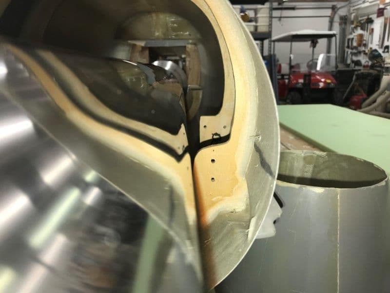
I inserted a 12m carbon tube into the existing mounting holes through the fuse to check the clearance of the pipe. There is a large void on the gel coat on the left stab root. I plan on not spending any time doing body work till I get all the systems working first.
Pipe sitting on the carbon rod on the bottom side.
With the pipe sitting on the carbon tube the pipe is way too high. This confirms what I suspected that the stab rods can not go all the way through the fuse with out interfering with the pipe. This requires that the stab pivots be two piece inserted from each side or the use of the trapeze cross beam if they are connected. I still want to try to have removable stabs for transport.
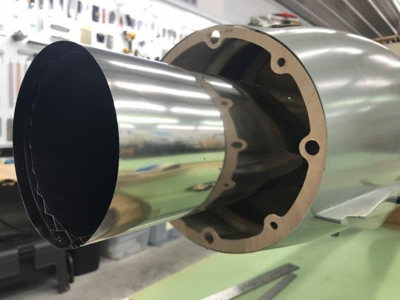
Dry fit of the aft former ring. I did not want to glue it in yet until I figure out how all the stuff in the rear end will work. A pipe supporting ring will have to be fabricated to hold the pipe in place at the aft former. I had Joey install an inside zig zag support ring between the inside and outside pipe at this location so the supporting ring will not cause the outer pipe to crush from its weight on the bottom.
Spent some time staring up the rear end figuring out how much room there is for a stab mounting bearing and servo on each side of the pipe. All TBD depending on if I can come up with a production stab mount system that will fit.
Last edited by Viper1GJ; 10-30-2018 at 05:06 PM.
10-30-2018, 05:36 PM
#147
Thread Starter
My Feedback: (20)
I took a look at the BVM 1/5 F-16 stab mount system today. This system could work in the F-105 if it is available separately from the factory. I checking with BVM about that now.
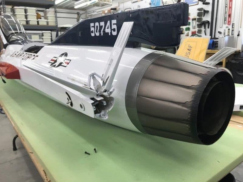
I removed the speed brake to expose the bearing assembly.
The stab bearing mounts to a bulkhead on the front.
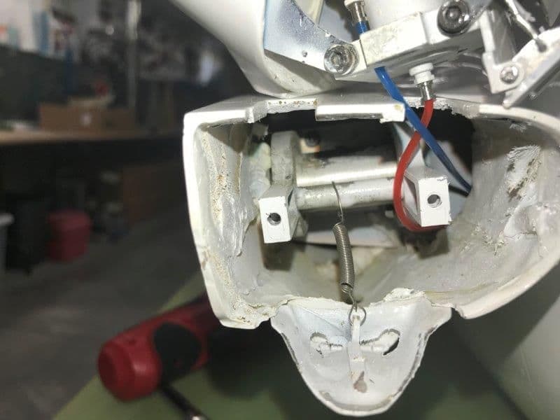
A clamp bolt on the bottom of the bearing sleeve holds the stab pivot tube in place. The clamp does not get any torque force. It only retains the stab in the bearing sleeve in the fuse. It looks like ball bearings on inside and outside of the clamp bearing sleeve. The rear speed brake mounts could be used on an aft former to secure the bearing between two formers.
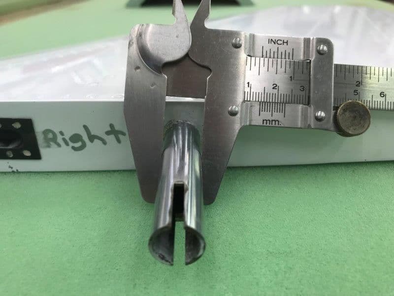
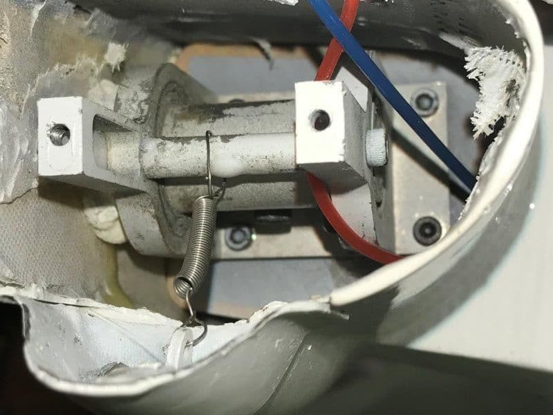
The stab tube is almost 14 mm here. The slot on the end engages a wire inside the bearing sleeve to align the clamp bolt to the bottom so it can be engaged by a ball driver from the bottom each time. It does not get any torque forces.
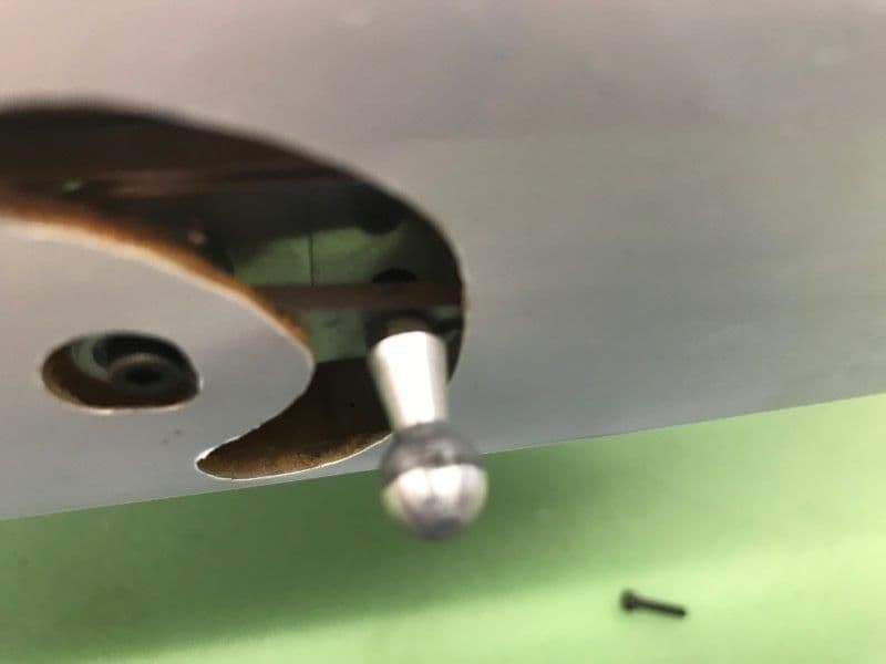
A ball stud driver is mounted to the servo arm inside and engages the drive slot in the stab.
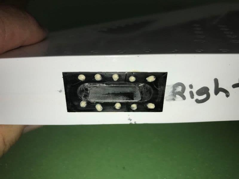
The plastic drive slot in the stab root. The holes are filled with hysol to secure the slot to the root rib. Mine has a G-10 shim inside to reduce slop.
I removed the speed brake to expose the bearing assembly.
The stab bearing mounts to a bulkhead on the front.
A clamp bolt on the bottom of the bearing sleeve holds the stab pivot tube in place. The clamp does not get any torque force. It only retains the stab in the bearing sleeve in the fuse. It looks like ball bearings on inside and outside of the clamp bearing sleeve. The rear speed brake mounts could be used on an aft former to secure the bearing between two formers.
The stab tube is almost 14 mm here. The slot on the end engages a wire inside the bearing sleeve to align the clamp bolt to the bottom so it can be engaged by a ball driver from the bottom each time. It does not get any torque forces.
A ball stud driver is mounted to the servo arm inside and engages the drive slot in the stab.
The plastic drive slot in the stab root. The holes are filled with hysol to secure the slot to the root rib. Mine has a G-10 shim inside to reduce slop.
Last edited by Viper1GJ; 10-30-2018 at 05:39 PM.
11-04-2018, 05:23 PM
#148
Thread Starter
My Feedback: (20)
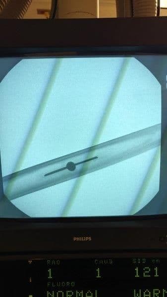
I had a friend that has access to an Xray machine take some scans of the stabs. The scans were not downloaded but photos were taken of the screen. This produced some diagonal video lines but did not obstruct the internal components. The idea was to find out if the currents stabs would be difficult to modify or would new stabs have to be built. It looks like the current stabs could be modified with a new pivot pin if necessary.
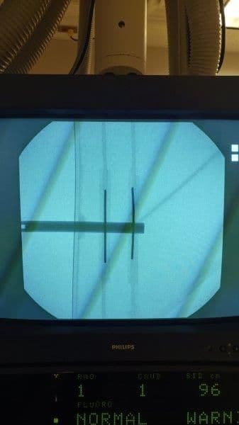
Top view shows two anti rotation pins glued to two rigs that have doublers on each side. The area about 2" aft of the existing pivot pin where the new pivot pin would go looks clear of obstructions.
End view from root
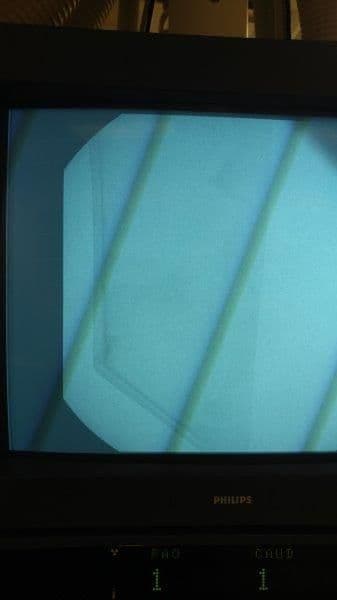
Tip of stab view
Top view shows two anti rotation pins glued to two rigs that have doublers on each side. The area about 2" aft of the existing pivot pin where the new pivot pin would go looks clear of obstructions.
End view from root
Tip of stab view
Last edited by Viper1GJ; 11-04-2018 at 05:30 PM.
11-04-2018, 06:07 PM
#149
Thread Starter
My Feedback: (20)
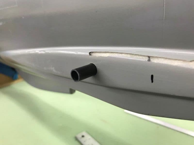
I needed to determine the available space between the pipe and fuse skin to install a stab bearing system. I placed the pipe in position and determined there was approximately 2" space available.
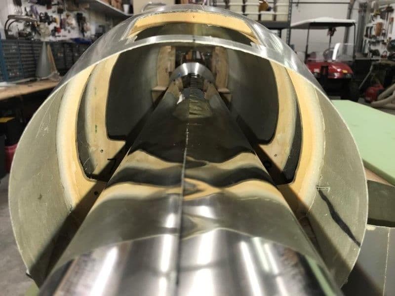
Stab mount bearings will have to be installed between the two rear formers on each side. The light reflections from the flash used to light the formers caused the pipe to look flat. Go figure.
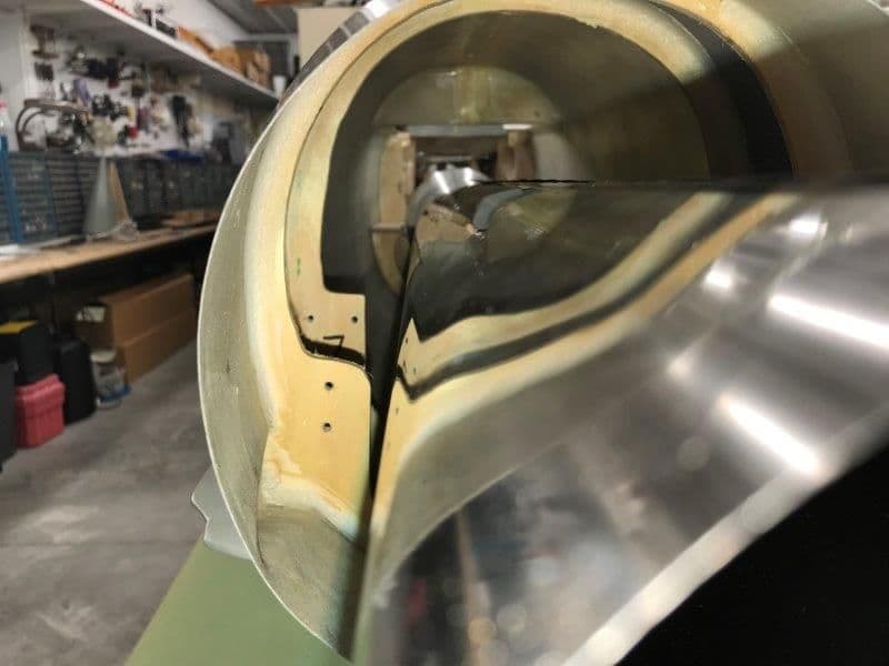
Left side
RIght side.
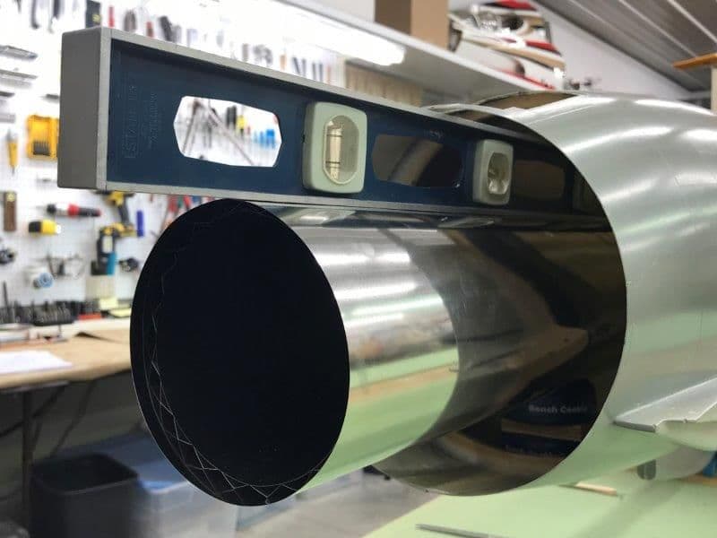
While checking the stab bearing space available I notice the pipe seemed to have about 3 degrees of up thrust. I started checking and leveled the fuse and checked the turbine mounting rails. They were level. I centered the pipe in the tail pipe hole and it was not even close to level. There was a definitely an up angle between the turbine and the pipe. I had uses the formers that came with the kit parts to set the level of the turbine rails but they were way off and that transferred to my plywood turbine formers. Arghhh, another glitch in the kit parts.
After shimming everything up to get it level and straight I found I needed to raise the pipe and turbine about 3/4" above the rails. Turbine shims shown here.
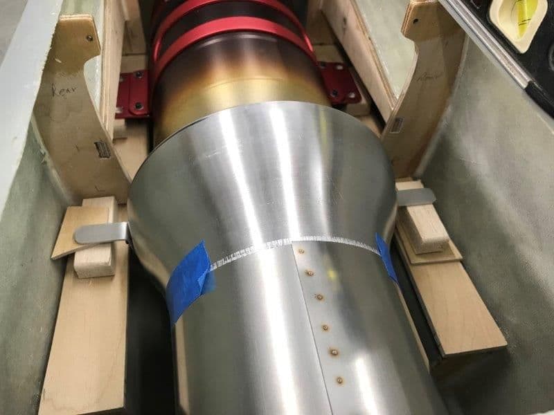
Pipe shims shown here.
Pipe centered in exit hole and now parallel with the turbine rails. I was initially frustrated but on second look it may actually help raising the turbine and pipe. It will prevent having to make a relief cut out in the turbine rails for the inside turbine bracket bolts avoiding a focus point of stress on the rails. Also it will raise the turbine intake more closely to the hole in the main wing former and probably make for smoother airflow to the turbine. I'll have to think through this for a while to see if I want to try to move the rails up or leave them in the current location and just shim the turbine and pipe to the proper level. Just more stuff to fix...
Stab mount bearings will have to be installed between the two rear formers on each side. The light reflections from the flash used to light the formers caused the pipe to look flat. Go figure.
Left side
RIght side.
While checking the stab bearing space available I notice the pipe seemed to have about 3 degrees of up thrust. I started checking and leveled the fuse and checked the turbine mounting rails. They were level. I centered the pipe in the tail pipe hole and it was not even close to level. There was a definitely an up angle between the turbine and the pipe. I had uses the formers that came with the kit parts to set the level of the turbine rails but they were way off and that transferred to my plywood turbine formers. Arghhh, another glitch in the kit parts.
After shimming everything up to get it level and straight I found I needed to raise the pipe and turbine about 3/4" above the rails. Turbine shims shown here.
Pipe shims shown here.
Pipe centered in exit hole and now parallel with the turbine rails. I was initially frustrated but on second look it may actually help raising the turbine and pipe. It will prevent having to make a relief cut out in the turbine rails for the inside turbine bracket bolts avoiding a focus point of stress on the rails. Also it will raise the turbine intake more closely to the hole in the main wing former and probably make for smoother airflow to the turbine. I'll have to think through this for a while to see if I want to try to move the rails up or leave them in the current location and just shim the turbine and pipe to the proper level. Just more stuff to fix...
11-04-2018, 06:48 PM
#150
Did I miss it, or once the thrust tube is level what is the clearance on each side for a set of elevator bearings? As for the turbine/thrust tube mounts, I would just glue big block shims in there with generous overlap over the existing rails. Just my take on it. I've done that before, too. Use plywood, even if you have to stack pieces together to get the 3/4" you need.