


1/6 F-105 Build Thread


 10-16-2018, 09:51 AM
#104

Yes I use hysol this way as well, vaseline for a quick and dirty release barrier. I use melted mold release wax as well.
This stuff is very light, sands amazing and is super strong for thin edges and will not chip. It is epoxy so it is strong and no shrink.
https://www.aircraftspruce.com/catal...clickkey=20637
This stuff is very light, sands amazing and is super strong for thin edges and will not chip. It is epoxy so it is strong and no shrink.
https://www.aircraftspruce.com/catal...clickkey=20637
10-16-2018, 04:44 PM
#105

Thread Starter
My Feedback: (20)
HI Matt,
I've used Super Fil before. Its good stuff. Rebuilt a burned up Eurosport a few years back and it was really good. I may get some more for this one. I have not tried Hysol on the seams. It sounds pretty easy to do so I may try that too. I'm pretty much not doing much body work till I can get it all built and may fly first. Just don't want to spend time and $ on looking pretty with so many functional issues to deal with first.
Gayr
10-16-2018, 04:52 PM
#106
Thread Starter
My Feedback: (20)
Installed magnets on nose formers. They were much stronger than I thought so I only put in two sets.
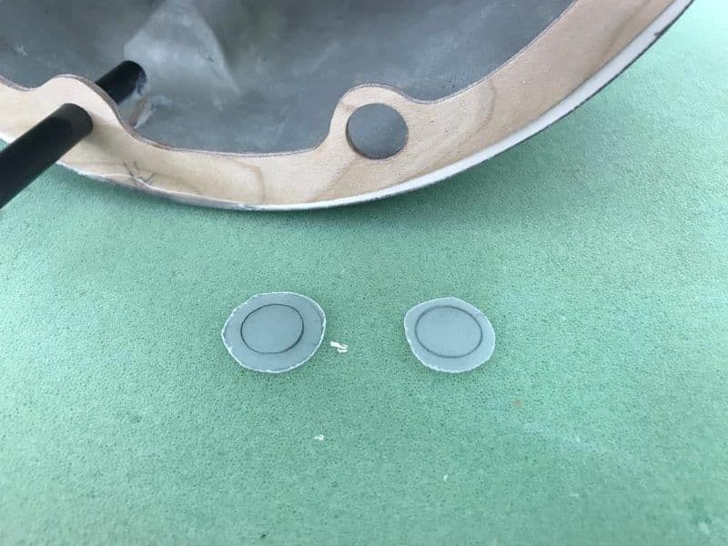
G10 discs cut to back the magnet holes
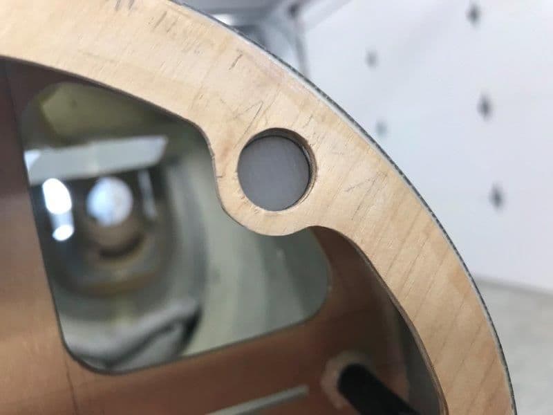
G10 discs glued behind magnet holes with med CA to give magnet disc a pocket for epoxy to grip on to
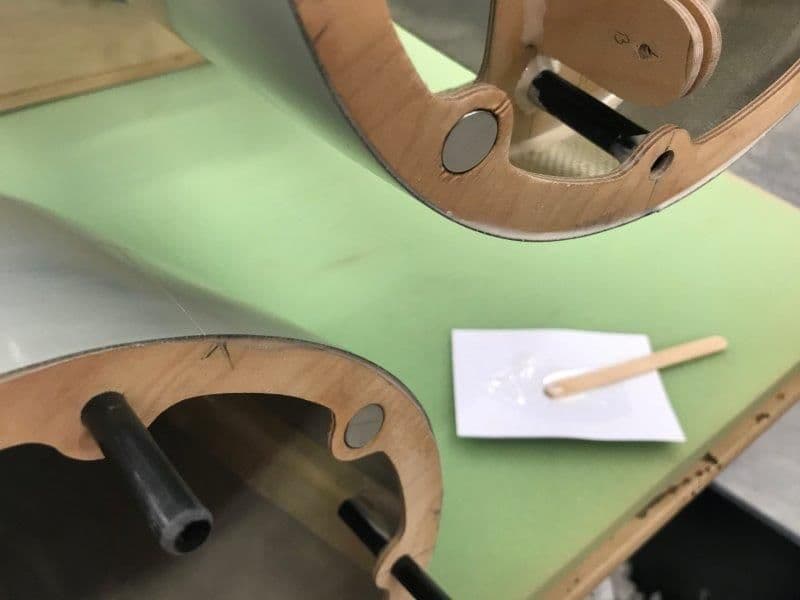
30 epoxy used to glue in magnets
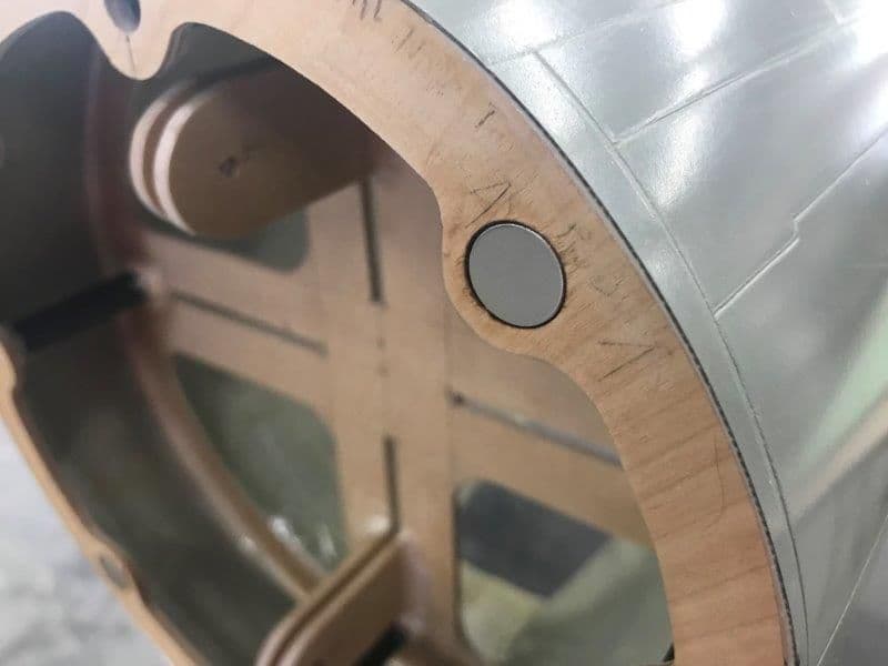
Magnets flush with surface of formers on both sides
Only two sets of magnets needed. They hold the nose on very firmly.
Magnets snap the nose on tightly and it takes a pull to get it off. Overall I'm pleased with results.
G10 discs cut to back the magnet holes
G10 discs glued behind magnet holes with med CA to give magnet disc a pocket for epoxy to grip on to
30 epoxy used to glue in magnets
Magnets flush with surface of formers on both sides
Only two sets of magnets needed. They hold the nose on very firmly.
Magnets snap the nose on tightly and it takes a pull to get it off. Overall I'm pleased with results.
10-16-2018, 05:01 PM
#107
Thread Starter
My Feedback: (20)
Same process used to install former in nozzle
8mm tubes aligned and squared to former and tack glued with med CA
Rear former tacked glued in with 5 min epoxy flush with front edge of nozzle cone
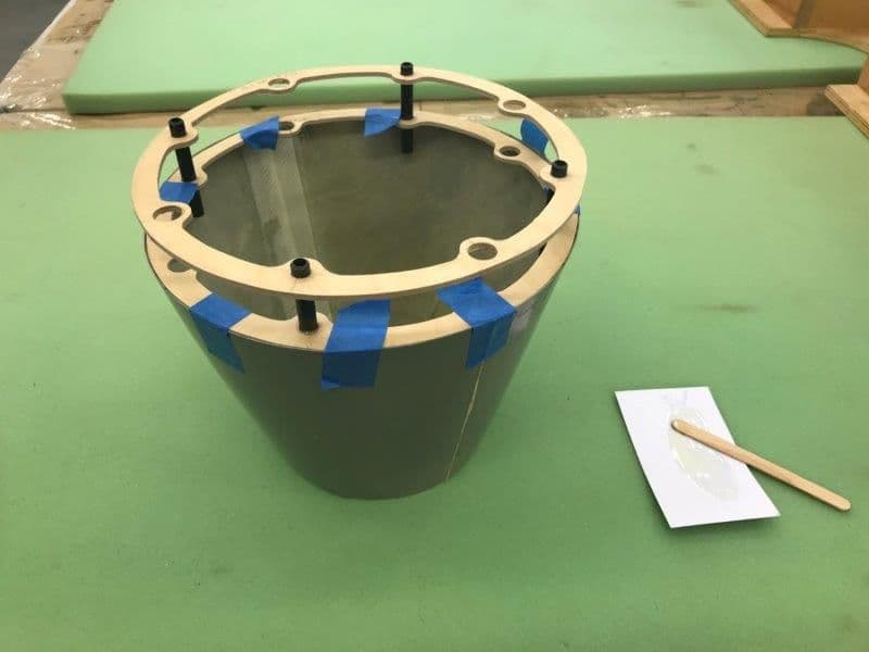
Fuse former pressed on to guide tubes to keep everything in alignment when curing. I will wait till the pipe arrives to install the former in the fuse.
8mm tubes aligned and squared to former and tack glued with med CA
Rear former tacked glued in with 5 min epoxy flush with front edge of nozzle cone
Fuse former pressed on to guide tubes to keep everything in alignment when curing. I will wait till the pipe arrives to install the former in the fuse.
10-16-2018, 05:23 PM
#108
Thread Starter
My Feedback: (20)
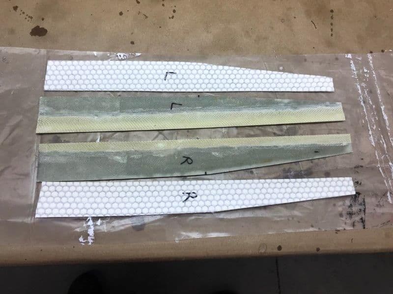
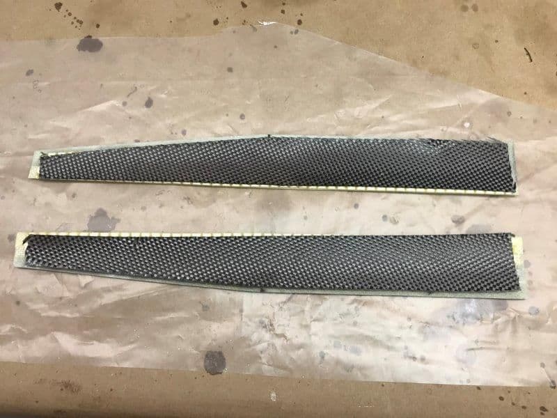
My F-105 kit did not come with NG doors so I planned to use the cut outs from the fuse NG well as substitute gear doors since they have slight compound curved shape. However they are very thin and flexible.
I tried to stiffen up my improvised nose gear doors by laminating some Aero-Mat material I found in my composites scrap box. I had never used it before and found out it was not the best material for the job.
 .
.
Aero-Mat cut to shape to laminate on inside of NG doors
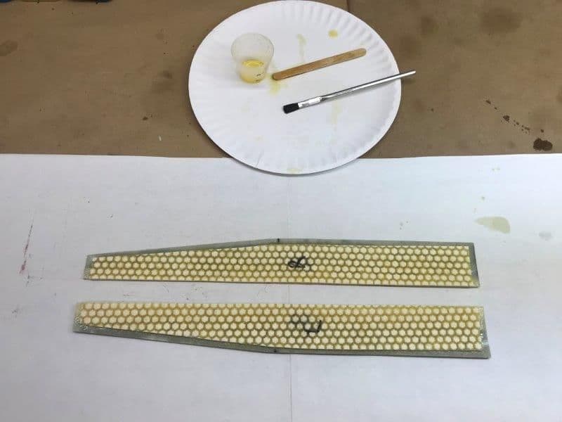
Aero-Mat core material did not work well. It really absorbed lots of resin and only added weight. The doors were still very flexible.
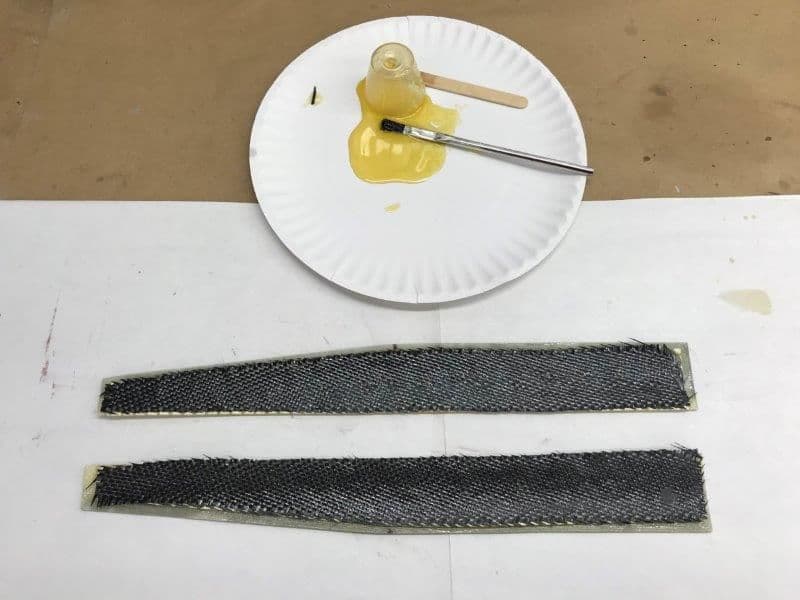
I decided to try something else. After the first layer cured I cut some 5.7 oz carbon cloth to try again.
I blotted the excess resin with paper towels and left it like this. Will find out if it worked tomorrow.
I tried to stiffen up my improvised nose gear doors by laminating some Aero-Mat material I found in my composites scrap box. I had never used it before and found out it was not the best material for the job.
.Aero-Mat cut to shape to laminate on inside of NG doors
Aero-Mat core material did not work well. It really absorbed lots of resin and only added weight. The doors were still very flexible.
I decided to try something else. After the first layer cured I cut some 5.7 oz carbon cloth to try again.
I blotted the excess resin with paper towels and left it like this. Will find out if it worked tomorrow.
10-16-2018, 06:53 PM
#109

My Feedback: (24)
Great thread, enjoying following along! I used the same method on the removable nose cone on my Yellow F-18, but used K&S tubing vs carbon.
The carbon should do the trick on the doors. Can also try gluing on some 1/16-1/8 balsa on the inside. Keep it back from the edges, bevel it, then glass over it on the back side. Alternate method is .005-.007 G-10 for the inner skin, a little bit heavier, but super strong. Foam will work for the core as well, works great for making nice stiff doors
The carbon should do the trick on the doors. Can also try gluing on some 1/16-1/8 balsa on the inside. Keep it back from the edges, bevel it, then glass over it on the back side. Alternate method is .005-.007 G-10 for the inner skin, a little bit heavier, but super strong. Foam will work for the core as well, works great for making nice stiff doors
10-17-2018, 02:53 PM
#110
Thread Starter
My Feedback: (20)
The CF backing over the Aero-Mat worked great on the NG doors. Very rigid and stiff now and will work well.
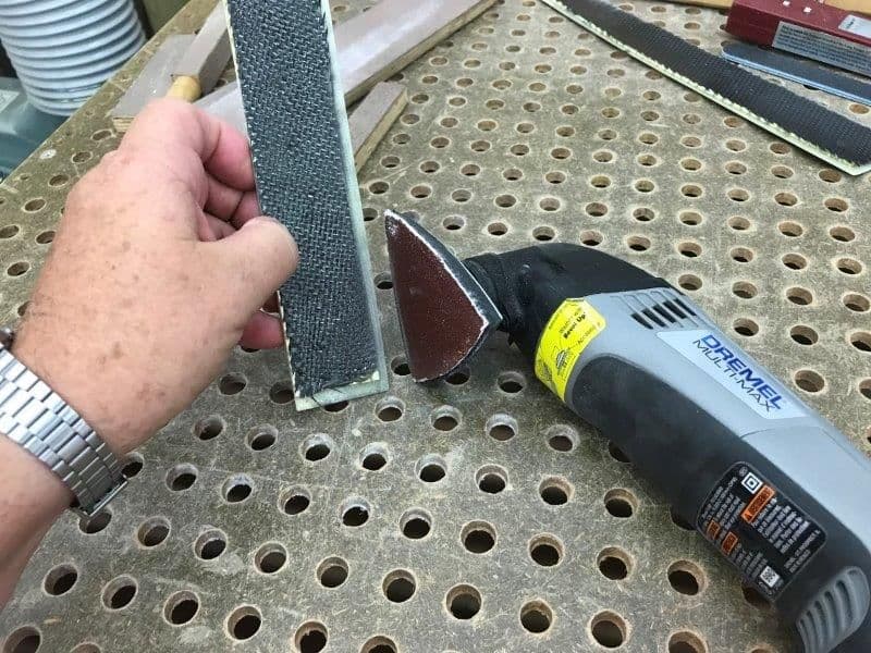
CLeaned up the edges with the Dremel sander and hand sanders over the dust table.
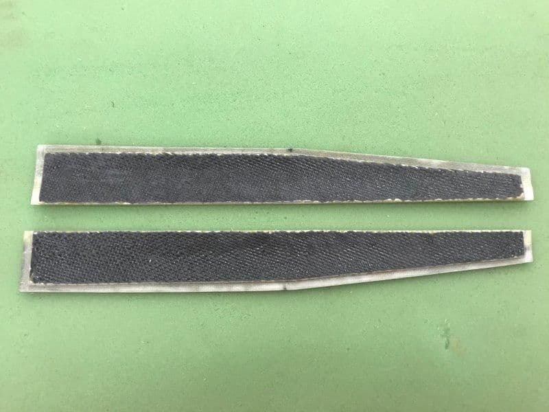
All done ready for hinges.
CLeaned up the edges with the Dremel sander and hand sanders over the dust table.
All done ready for hinges.
10-17-2018, 03:12 PM
#111
Thread Starter
My Feedback: (20)
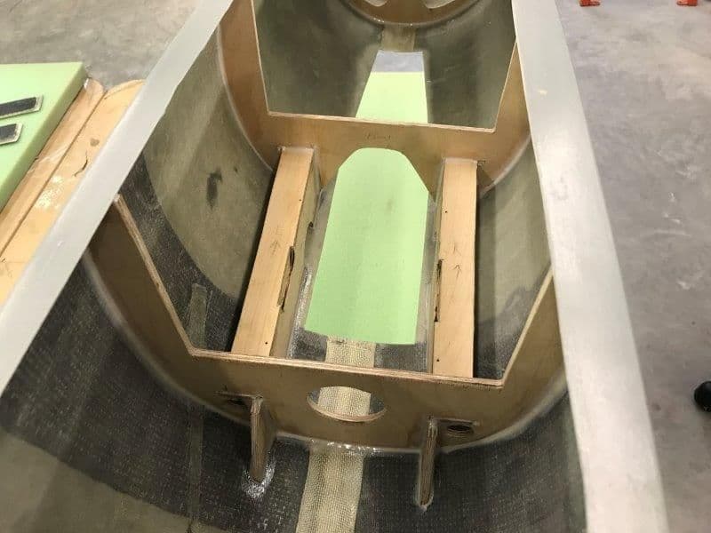
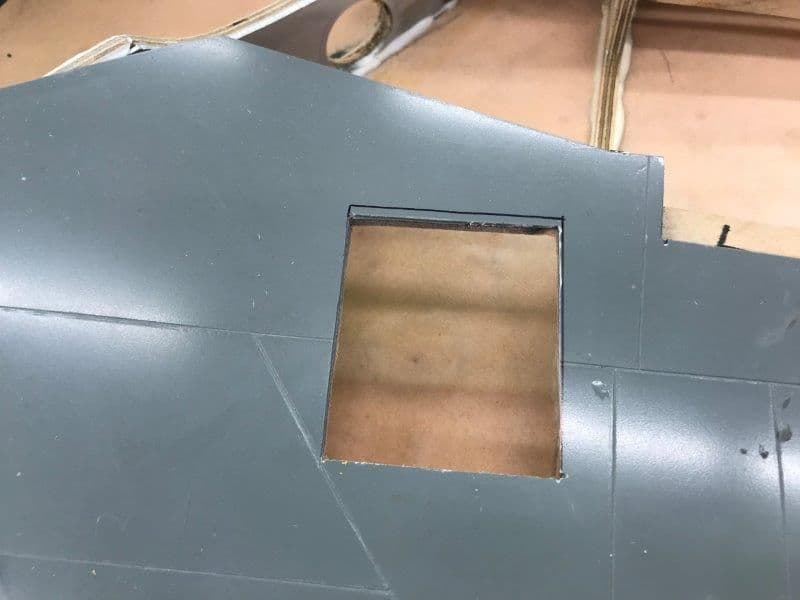
Installed the nose gear mounts into the fuse with hysol.
The layout inside the fuse was marked with pencil. Measurements were taken from front of fuse to ensure formers were square and vertical. Then I spent some time planning the sequence of hysol application and parts placement since everything locks together. I did a dry practice run and preplanned the movements to avoid the "hysol mess" as much as possible.
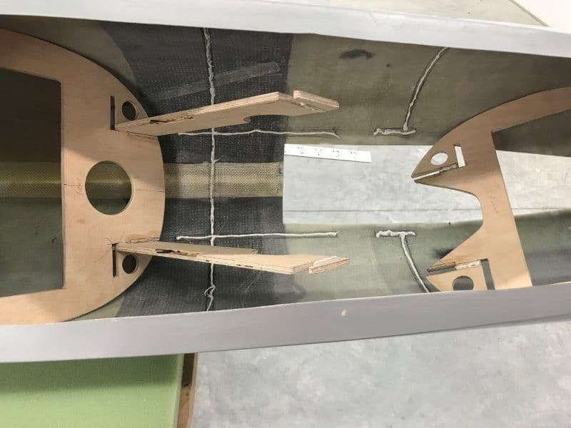
First hysol applied to marks inside the fuse. Then hysol applied to slot overlaps on formers and formers placed inside fuse. Next hysol applied to vertical rails and rails engaged to rear former. Next rear former and rails pushed forward to engage front former to the rails. Then whole assembly placed into position. Joints hidden under the top mounts got a hysol fillet first. Then the top rails were added and pushed into position. Finally all joints got hysol fillets all around.
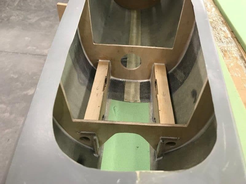
I used the finger applicator for making hysol. The whole process took about an hour.
Small paper towel squares, Q-tips, and alcohol used to clean up messes. Overall I was happy and it seems to have come out OK.
The layout inside the fuse was marked with pencil. Measurements were taken from front of fuse to ensure formers were square and vertical. Then I spent some time planning the sequence of hysol application and parts placement since everything locks together. I did a dry practice run and preplanned the movements to avoid the "hysol mess" as much as possible.
First hysol applied to marks inside the fuse. Then hysol applied to slot overlaps on formers and formers placed inside fuse. Next hysol applied to vertical rails and rails engaged to rear former. Next rear former and rails pushed forward to engage front former to the rails. Then whole assembly placed into position. Joints hidden under the top mounts got a hysol fillet first. Then the top rails were added and pushed into position. Finally all joints got hysol fillets all around.
I used the finger applicator for making hysol. The whole process took about an hour.
Small paper towel squares, Q-tips, and alcohol used to clean up messes. Overall I was happy and it seems to have come out OK.
Last edited by Viper1GJ; 10-17-2018 at 03:15 PM.
10-17-2018, 03:20 PM
#112
Thread Starter
My Feedback: (20)
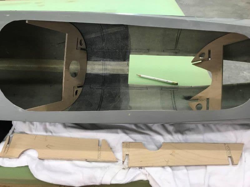
Air duct cutouts on wing spars smoothed out.
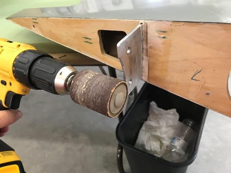
Drill sanding drum used to smooth rough saw cut on spar.
Final smoothing done by hand with wet dry 150 grit paper. WIng spars done!
Drill sanding drum used to smooth rough saw cut on spar.
Final smoothing done by hand with wet dry 150 grit paper. WIng spars done!
 10-18-2018, 04:00 PM
#115
Thread Starter
My Feedback: (20)
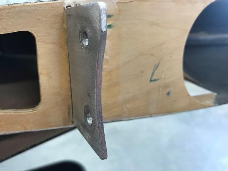
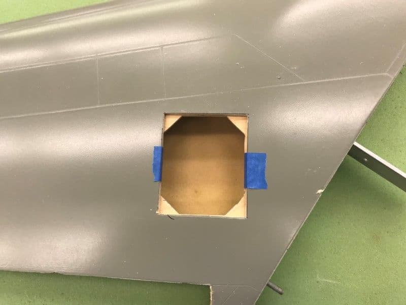
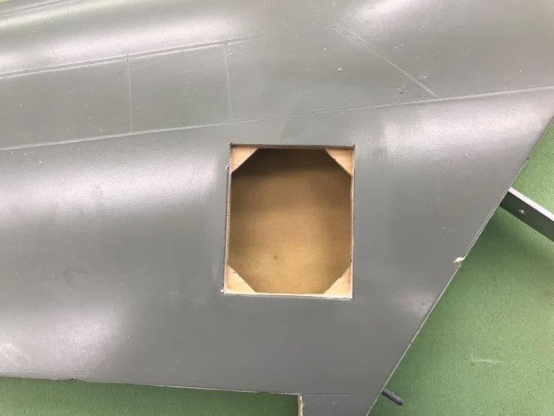
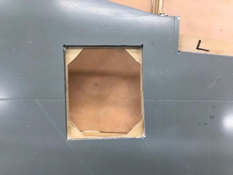
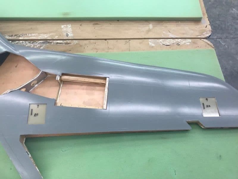
Five servo wells prepared with ply corner gussets for 1/16" G10 covers that will hold servo brackets.
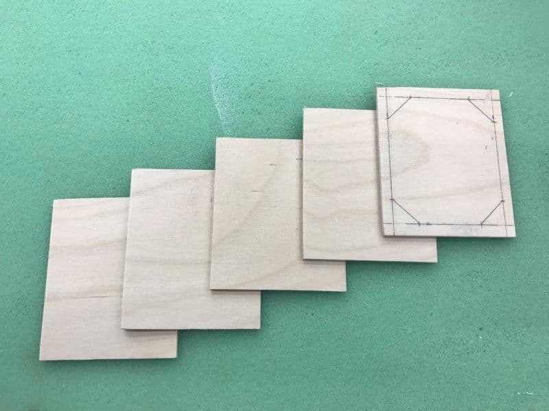
1/8" ply corner brackets cut and marked for internal cuts
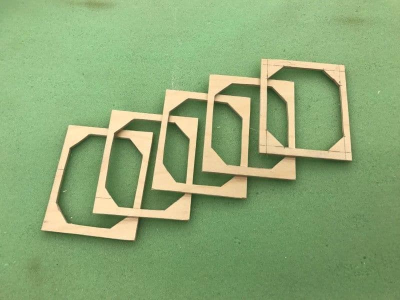
Internal cuts made and ply brackets ready for dry fits.
Each servo well had to be enlarged to accept the metal servo mounting brackets to be attached to the G10 covers.
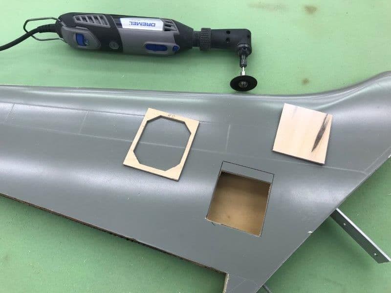
Left flap well marked and ready to cut
Dry fit on fin. Each servo well was different do to variations in how wings were made and each well had to be custom fit with a Dremel grinder to make the ply brace fit. Nothing is ever easy.
Hysol applied and fin bracket put in place.
Left flap well with hysol applied. The G10 covers will screw into the corner gussets.
1/8" ply corner brackets cut and marked for internal cuts
Internal cuts made and ply brackets ready for dry fits.
Each servo well had to be enlarged to accept the metal servo mounting brackets to be attached to the G10 covers.
Left flap well marked and ready to cut
Dry fit on fin. Each servo well was different do to variations in how wings were made and each well had to be custom fit with a Dremel grinder to make the ply brace fit. Nothing is ever easy.
Hysol applied and fin bracket put in place.
Left flap well with hysol applied. The G10 covers will screw into the corner gussets.
Last edited by Viper1GJ; 10-18-2018 at 04:02 PM.
10-22-2018, 05:12 PM
#116
Thread Starter
My Feedback: (20)
Fabricated servo well covers from 1/16" G10 sheet
Each cover placed and marked for direction and servo arm slot
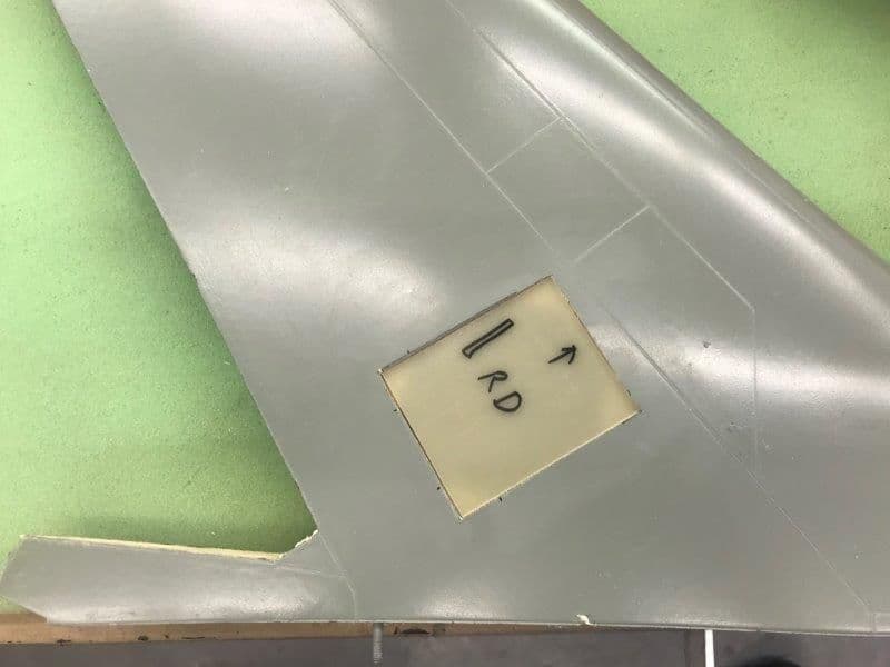
Closeup of rudder servo cover
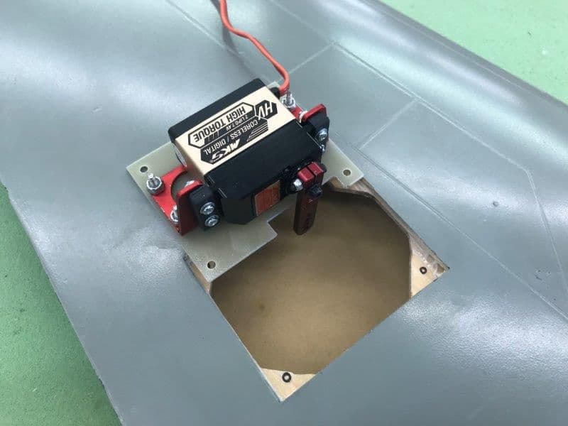
Cover drilled, countersunk, and cut with servo bracket and servo mounted ready for fitting
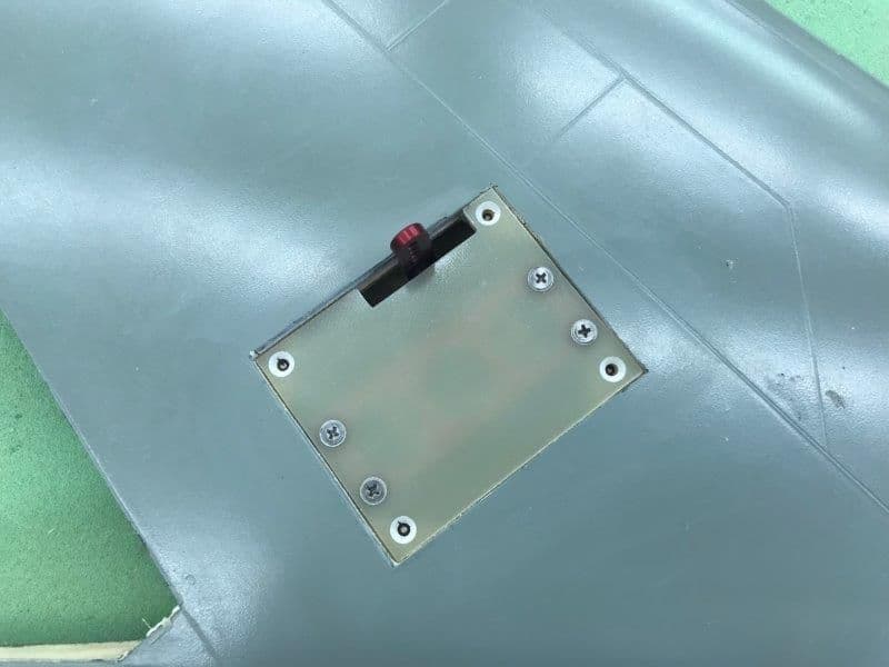
Final fit after some minor sanding on edges. Some shims needed to raise cover flush with skin surface.
Each cover placed and marked for direction and servo arm slot
Closeup of rudder servo cover
Cover drilled, countersunk, and cut with servo bracket and servo mounted ready for fitting
Final fit after some minor sanding on edges. Some shims needed to raise cover flush with skin surface.
10-24-2018, 04:29 PM
#117
Thread Starter
My Feedback: (20)
Re post of my post on Paul's Buccaneer thread. I did not want to clutter his amazing build thread with my F-105 stuff.
Paul,
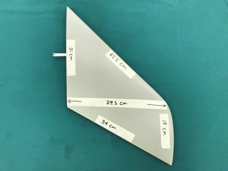
Here is a photo I took a couple of months ago when starting to think about the stab issues. Its approximate. The problems are, pivot point in wrong place, poor airfoil, inadequate pivot pin size and material, and unusable stab actuating mechanism. My current solution is to scrap the supplied stabs and mounts and start over with a new stab and mounting design. That's as far as I have gone on it. It will require making new stabs with a good airfoil and a new mounting solution. I want the stabs to be removable for transportation.
Thanks, Gary
Paul,
Here is a photo I took a couple of months ago when starting to think about the stab issues. Its approximate. The problems are, pivot point in wrong place, poor airfoil, inadequate pivot pin size and material, and unusable stab actuating mechanism. My current solution is to scrap the supplied stabs and mounts and start over with a new stab and mounting design. That's as far as I have gone on it. It will require making new stabs with a good airfoil and a new mounting solution. I want the stabs to be removable for transportation.
Thanks, Gary
10-24-2018, 04:38 PM
#118
Thread Starter
My Feedback: (20)
Trying to get a concept of how to mount and operate a new stab design for the F-105
I discussed with Larry who is also building one of Bob's 105 kits his idea for the stab mounting and linkage. His idea is to have stab tube plug into the fuse and operate the stab with direct drive ball and socket arrangement similar to the Skymaster and BVM F-16 stabs. He is thinking about the SM spring retainer vs the BVM clamp style of retaining the stab tube in the fuse.
Does anybody have ideas of what materials to make this work such as the size of the stab pivot tube, bearing material, and where to get it?
Matt, how do you mount the F5 stabs?
10-24-2018, 06:48 PM
#120
Gary - great to talk to you.
The concept will be to 3D print a new tailplane plug, make a mold and produce a new set of tailplanes.
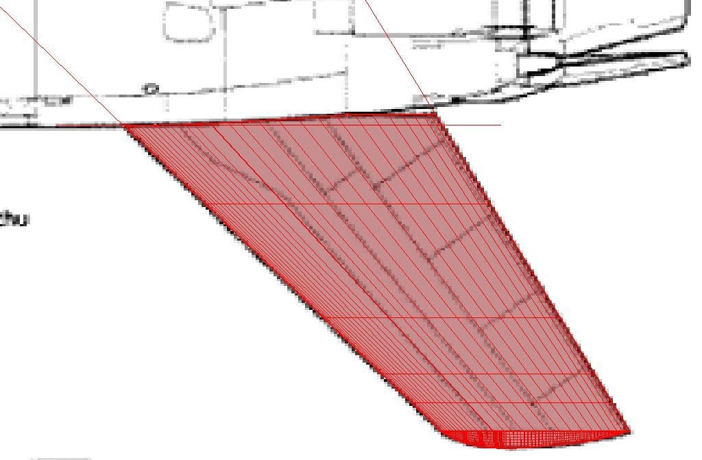
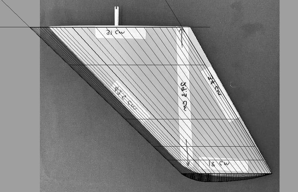
After downloading a couple of 3 view drawings I found that Gary's original tailplane did not match the 3 views. Gary is going to do some more research with Butch (original builder of the 105) to see which shape is correct before we proceed much further.
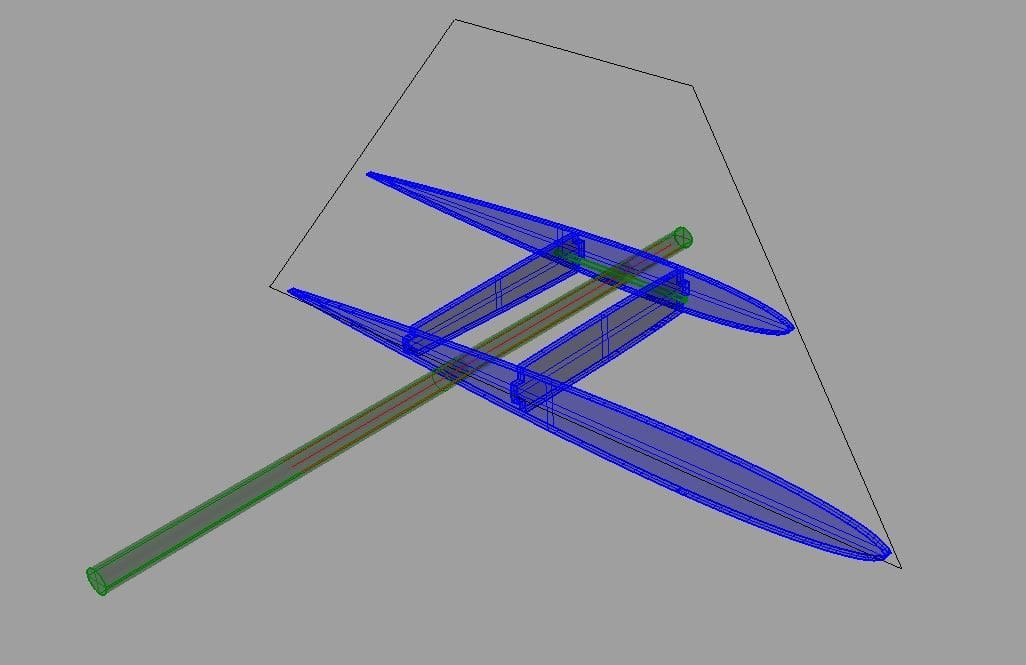
NACA 0009 was used for the airfoil section with the pivot point at 23% mac.
I produced an initial concept for the internal structural arrangement. Skins will be glass covered 1/16" balsa with ribs of 5-ply birch plywood with a couple of interlocking short spars to form a box section. The pivot rod, made out of 7075 3/8" Al rod will have a 1/8" cross bar drilled through it to act as a torsion restraint which will lock into the spars. I'm still contemplating a further spar to run out to the tip, potentially with a final tip rib. Lightening holes will be cut into the ribs where appropriate.
It should be a simple and quick project once we nail down a few key dimensions, including the fuselage mounted tailplane attachment and pivot method.
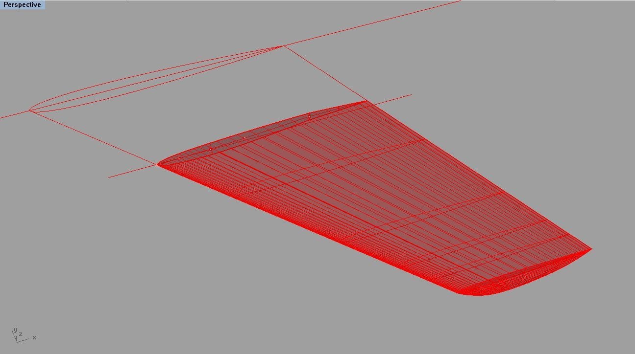
The concept will be to 3D print a new tailplane plug, make a mold and produce a new set of tailplanes.
After downloading a couple of 3 view drawings I found that Gary's original tailplane did not match the 3 views. Gary is going to do some more research with Butch (original builder of the 105) to see which shape is correct before we proceed much further.
NACA 0009 was used for the airfoil section with the pivot point at 23% mac.
I produced an initial concept for the internal structural arrangement. Skins will be glass covered 1/16" balsa with ribs of 5-ply birch plywood with a couple of interlocking short spars to form a box section. The pivot rod, made out of 7075 3/8" Al rod will have a 1/8" cross bar drilled through it to act as a torsion restraint which will lock into the spars. I'm still contemplating a further spar to run out to the tip, potentially with a final tip rib. Lightening holes will be cut into the ribs where appropriate.
It should be a simple and quick project once we nail down a few key dimensions, including the fuselage mounted tailplane attachment and pivot method.
 10-25-2018, 05:10 AM
#122

Gary - great to talk to you.
The concept will be to 3D print a new tailplane plug, make a mold and produce a new set of tailplanes.
After downloading a couple of 3 view drawings I found that Gary's original tailplane did not match the 3 views. Gary is going to do some more research with Butch (original builder of the 105) to see which shape is correct before we proceed much further.
NACA 0009 was used for the airfoil section with the pivot point at 23% mac.
I produced an initial concept for the internal structural arrangement. Skins will be glass covered 1/16" balsa with ribs of 5-ply birch plywood with a couple of interlocking short spars to form a box section. The pivot rod, made out of 7075 3/8" Al rod will have a 1/8" cross bar drilled through it to act as a torsion restraint which will lock into the spars. I'm still contemplating a further spar to run out to the tip, potentially with a final tip rib. Lightening holes will be cut into the ribs where appropriate.
It should be a simple and quick project once we nail down a few key dimensions, including the fuselage mounted tailplane attachment and pivot method.
That is very similar to what i would do (and have done on a few models). Only changes i would make are to increase the size of the pivot shaft to 1/2� if able and to add the spar to the horizontal stab. A tip rib isnt necessary as the 1/16� balsa sheeting with the proper glass weights will provide ample torsional strength.
10-25-2018, 06:33 AM
#123
Thomas,
I think we could enlarge the shaft to 1/2". The rib depth at the pivot point is approx 18mm (offset for skin thickness), so that would leave 3mm of rib material either side of the shaft. Gary was going to research a suitable mount/ pivot set-up (maybe an off the shelf 1/5 F-16 horizontal stab mount), so that will likely define the shaft diameter we will use.
Paul