


1/6 F-105 Build Thread

 12-28-2018, 07:47 PM
#227

Gary,
I did some VERY crude calcs, making a lot of assumptions. I do engineering calcs in metric, so I converted all to metric units.
Span = 5.83ft = 1.775m
Center of lift at 1/2 semi-span = 0.44375m
Max weight = 50lb = 22.7Kg
Spar Depth = 6cm
Proposed Hole cut out = 2" = 5cm
Min spar depth at hole = 0.5cm
Wing Bending Moment on centerline at 5g = 22.7*9.81*5*0.44375 / 2 = 246Nm
Wing Bending Moment on centreline at 10g = 492Nm
Tension in bottom of spar at centreline at 5g = 246*1000/30=8,200N
Tension in bottom of spar at centreline at 10g = 492*1000/30=16,400N
Stress in bottom of spar, 1/8" thick = 8,200 / (0.003 * 0.005) at 5g = 550 MPa
Stress in bottom of spar, 1/8" thick = 16,400 / (0.003 * 0.005) at 10g = 1100 MPa
For Al 7075, Tensile Yield Strength = 503MPa
For our application, I would not use more than 50% allowable strength, plus you need at least a 50% safety factor, so a max allowable would be around 165MPa.
From these CRUDE cals, I don't think you could stand any significant lightening hole in the spar, let alone one 2" in diameter - the bottom of the spar would fail in tension at way less than 5g.
There are more precise calculations (M/I = Stress/ y) which could be done with the correct measurement of the proposed spar design, which may lower the stresses, but either way I think you need more minimum spar depth than you currently show.
Paul
 12-29-2018, 07:17 AM
#228
Gary,
I re-did the calculations using the standard bending equation (Stress = M.y/I) but based on the same very crude assumptions above.
For a 6cm deep spar with a 2" (5cm) hole and 1/8" (3mm) thick, that gave an I = 2.275x10^-8m^4.
Using that I in the equation gives a max stress of 326MPa for a 5g maneuver, which is still about double a safe maximum for 7075.
Out of interest, a solid 6cm by 3mm (1/8") spar gives a max stress of 137MPa, which is acceptable.
Hopefully if you can provide some accurate measurements of the proposed spar, the calculations will be more representative. A 6cm spar does seem a little large, but I was scaling from your drawing and the comment that the hole was 2".
Paul
12-29-2018, 01:04 PM
#229

Thread Starter
My Feedback: (20)
Hi Paul,
Thank you so much for sharing your talent, knowledge, and skill. Your post made me realize I was approaching the problem incorrectly. I was thinking more about feeding air to the turbine. What I should be thinking about first is what kind of spar will it take to hold the wings on so it could be safely flown. Then I can worry about air to the turbine.
I was planning to use .125 1/8" thickness because that is what was already there. I was worried about the wood former failing and never considered that the existing 1/8" spar tab could fail also. I would have probably used a thicker material or a tube design spar on the original design but for now I'm trying to work with what came with the existing parts. Plus there are also the existing mounting holes that have to be used to mount the spar to the fuse and wings.
I think 50 lbs or 22.7 Kg is not possible. Based on Bob Rullies build with a P300 I fully expect 60-65 lbs with fuel.
The spar template is 7 cm deep across the fuse. Can I send you more accurate measurements of the wings but what would you need? The 7075-T6 bare sheet plate aluminum I was going to order is listed on www.onlinemetals.com. They have the following thickness:
.125" 1/8"
.16" 5/32"
.19" 3/16"
.25" 1/4"
What size would work and if it were thicker could you still get some air holes in and still meet strength requirements? I can use the thicker material up to 1/4", its just harder for me to cut.
If you are willing I would really appreciate if you could assist me making a safe wing spar. There is too much safety risk, not to mention time, effort, and money to make a dumb mistake based on an uneducated guess.
Thanks,
Gary
Last edited by Viper1GJ; 12-29-2018 at 01:10 PM.
12-29-2018, 04:00 PM
#230
Gary,
No problem.
So, with a 65lb model and a 70mm spar depth I re-did the calcs.
The quickest way to lower the stresses is to increase the Area Moment of Inertia of the spar, which , with a given spar depth is to increase the thickness. I went straight for 1/4" (6mm).
A solid 70x6mm spar has an I of 171.5x10^-9m^4.
Adjusting the center of lift to a more reasonable 40% of semi-span gives a lift moment arm of 0.355m.
With 65lb (29.5kg) = 289N acting at the nominal center of lift, that gives a root bending moment per side of 51.4Nm/g
For 5g = 257Nm per side
For 10g = 514Nm per side
What I missed earlier is that both wing halves are lifting, thereby doubling the stress at the center-line, so the total bending moment at the center-line is;
For 5g = 514Nm
For 10g = 1028Nm
With that, the stress in the spar is M.y/I, which gives,
For 5g = 105MPa
For 10G = 210MPa
If you add an elliptical lightening hole 30mm deep, that reduces the I at the center-line to 158x10^-9m^4, and increases the stresses to;
For 5g = 114MPa
For 10G = 228MPa
If you use the 30mm deep elliptical lightening hole, it would need to be 122mm wide to get the area the same as the 3x 1 3/8" (35mm) holes that you proposed.
The 3 1 3/8" holes would probably not increase spar stresses significantly more that would risk a 5g capability.
I'd like someone else (Oli??) to double check my calcs - its been a long time since I did wing stressing, but as you only have one spar, a 1/4" spar doesn't sound unreasonable. Most models with blade spars have 2 spars that are at least 1/8" thick, so a single spar needs to be thicker.
Paul
12-29-2018, 05:21 PM
#231
Thread Starter
My Feedback: (20)
Paul,
Thanks for your work. Although I don't understand the calculations or some of the units, I followed the logic and think I understand the conclusions. As I understand, the 1/4" spar with no holes would give the lowest Mpa number at a given G force. This means the least stress in the spar material and lowest risk for failure at a given G force. I will have to find a way to get air to the turbine above and below the spar in that case.
What is the failure Mpa of the 1/4" spar and what margin is there at 5 and 10 G?
onlinemetals offers a .375 3/8" thickness. It gets harder to cut and shape with a jig saw and hand tools but it could be used. I think that's about the practical limit with out major redesign and fabrication of a totally different wing spar and mounting system, which I really don't want to do.
Thanks,
Gary
12-29-2018, 06:02 PM
#232


Gary,
I can't do the math and formulas due to a lack of understanding but here is what I know.
the original spar design is suspect. Having said that there has been at least one of these jets flying right?
if it were me I would take your 1/4" aluminum spar as per your design. Put in a couple of holes for airflow and bolt it into the fuse. Part of what still needs to be considered is that you are still using the original 4 bolts to mount the spar to the wood former that is going to take some of the load. If the jet has worked in the past with those 2 small 1/8" formers and you are now tying the entire assembly together via a solid spar that is bolted to that same former you have already more than doubled the strength of the design. All the math in the world is great but at the end of the day sometimes the TLAR method (that looks about right) proves to work just as well. When I consider the size of the spars in my F5, F16, etc I think your design using 1/4" material will be plenty strong. At least with the one piece spar you can check. After you build it make a very accurate tracing of it. After you fly it check it against that tracing again. If you note any deformation then we will figure something else out but I suspect unless you try to do pylon turns you will be more than fine.
just my opinion.
12-29-2018, 06:06 PM
#233

Gary what if you could fabricate a bullet or bubble nose that you could snap onto that middle of the aluminum plate to help smooth the airflow as it tumbles over the section that protrudes through the middle of the intake . Envision a bubble on at the front of a a wells cargo trailer. Increase the plywood former cut out in that area since it�s no longer the main carry through any longer. there�s a possibility of adding blow in doors if you�re still concerned about airflow to the engine .
12-30-2018, 08:13 AM
#234
Gary,
If we assume a safe maximum allowable stress for AL 7075, with appropriate safety factors is 165MPa. That takes into account material uncertainties and a 1.5 safety factor on the loads to yield, then a 1/4" spar with the 3x 35mm air holes will be fine.
That spar configuration will result in a maximum center-line stress of 120MPa at 5g, and 240MPa at 10g. 6.8g generates the limiting stress of 165MPa.
Based on flying mu Ultra Flash with a real-time accelerometer, 10g is a very aggressive pull, not something to be done with a scale model. 5g should be plenty. Landing loads in this config (main gear in the wing) will impart high loads into the spar too though, so that needs to be another consideration.
I think that your 70x6mm spar with the 3x 35mm air holes will be adequate, but again I'd prefer my recommendation to be checked by someone else. Jeremy's TLAR suggestion is always a good back-up too and I think that the 6mm spar passes that test too.
The next consideration is the mounting method of the spar to the wings. Bolting or gluing? You could see some bearing failure of the plywood spars if the bolts are insufficient.
Paul
01-02-2019, 04:37 PM
#235
Thread Starter
My Feedback: (20)
Trying to get some shop time going again after the holidays. Many thanks for all the help and ideas for the wing spar.
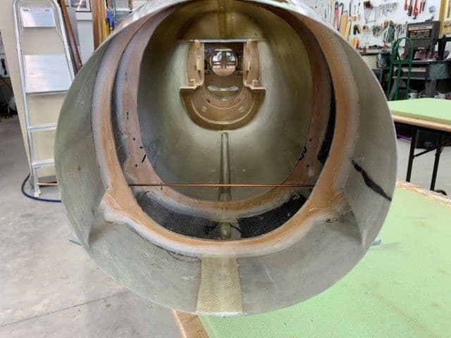
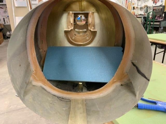
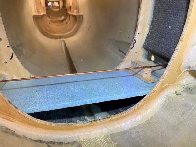
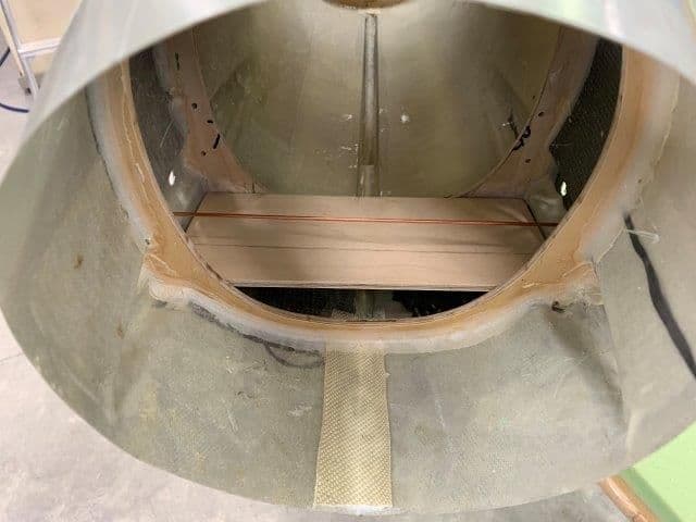
I'm going with the 1/4" 7075 spar plate. Aluminum ordered today. I will start with no holes in the center and see if I can enlarge the plywood former above and below the spar plate enough to get air to the turbine. The center of the turbine is actually below the center of the hole. The existing hole is 12 cm in diameter. I have no idea why it is this size but I understand the prototype was flown on a P200. I like the idea of an aerodynamic shape in front of the spar plate to smooth the airflow but there are fuel tanks just forward of the spar so that will have to be considered.
The new aluminum spar plate will extend into the wing to the gear well area and bolt to the aluminum and plywood wing spar there. I think the 1/8" aluminum and 1/4" plywood spar in the gear well will be plenty strong to bolt the new spar plate on to.
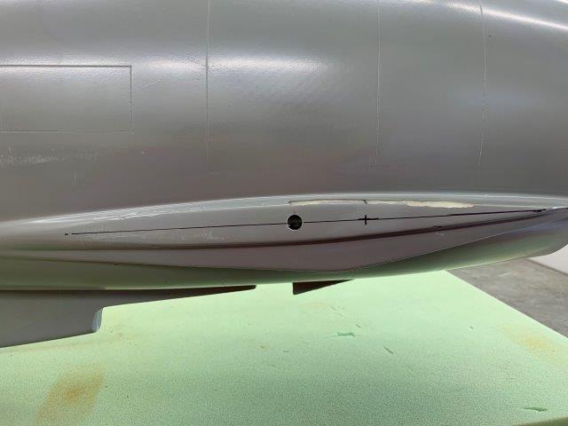
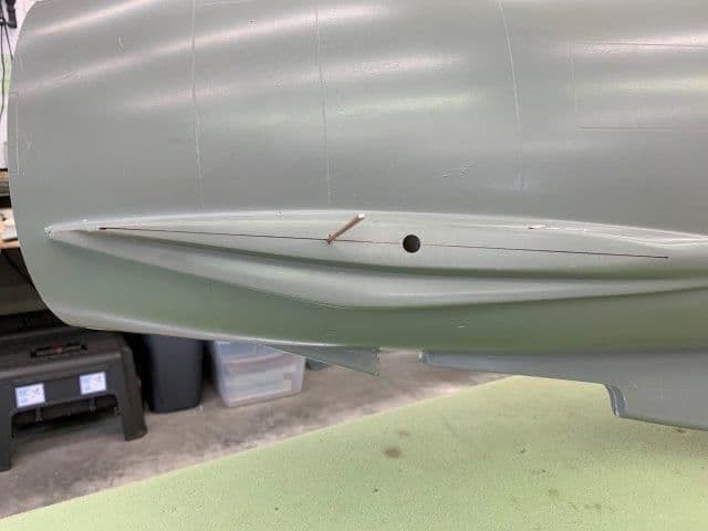
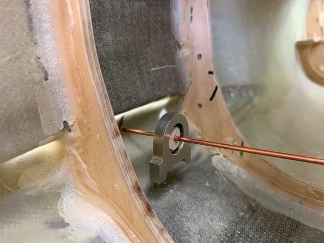
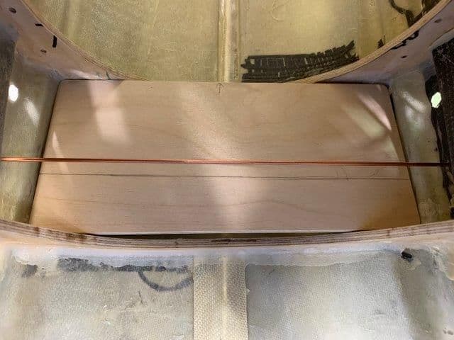
The only problem is the angle of the new spar plate relative to the existing spar tab and the wing spar. As seen in the photo below the spar tab is bent forward to align with the former inside the fuse. The aluminum and wood wing spar is not square with the wing root and the wing root has to fit inside the fuse pocket to secure the trailing edge wing mounting bolt. Therefore the new spar plate will not be flush with the aluminum wing spar inside the wing. This will require some custom made spacers between the existing aluminum spar and the new spar plate where the 4 1/4-20 bolts clamp the two together. Just more stuff to make.
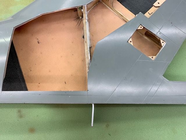
Existing wing spar is 1/8" aluminum and 1/4" plywood where the new spar plate will bolt to it with 4 bolts
I'm going with the 1/4" 7075 spar plate. Aluminum ordered today. I will start with no holes in the center and see if I can enlarge the plywood former above and below the spar plate enough to get air to the turbine. The center of the turbine is actually below the center of the hole. The existing hole is 12 cm in diameter. I have no idea why it is this size but I understand the prototype was flown on a P200. I like the idea of an aerodynamic shape in front of the spar plate to smooth the airflow but there are fuel tanks just forward of the spar so that will have to be considered.
The new aluminum spar plate will extend into the wing to the gear well area and bolt to the aluminum and plywood wing spar there. I think the 1/8" aluminum and 1/4" plywood spar in the gear well will be plenty strong to bolt the new spar plate on to.
The only problem is the angle of the new spar plate relative to the existing spar tab and the wing spar. As seen in the photo below the spar tab is bent forward to align with the former inside the fuse. The aluminum and wood wing spar is not square with the wing root and the wing root has to fit inside the fuse pocket to secure the trailing edge wing mounting bolt. Therefore the new spar plate will not be flush with the aluminum wing spar inside the wing. This will require some custom made spacers between the existing aluminum spar and the new spar plate where the 4 1/4-20 bolts clamp the two together. Just more stuff to make.
Existing wing spar is 1/8" aluminum and 1/4" plywood where the new spar plate will bolt to it with 4 bolts
01-04-2019, 04:43 PM
#236
Thread Starter
My Feedback: (20)
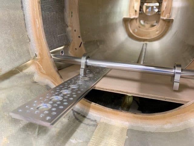
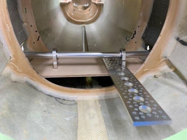
Stab drive parts arrived today. They are all from the Robotzone Actobotics line ordered from Servo CIty. The idea for this system came from Phil Clark at Fighteraces in the UK. I'm basically copying his idea and design except I'm using the prefabricated Actobotics metal base plates.
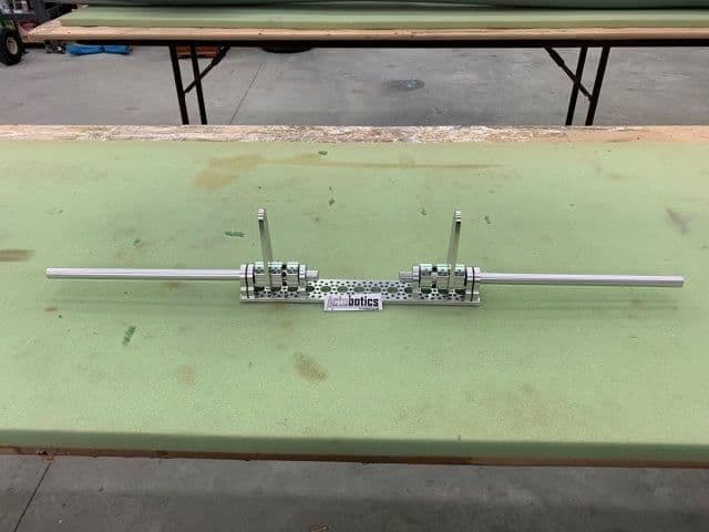
Parts mocked up for the proposed stab drive layout. The exhaust pipe will dip down between the two stab drive tubes in the rear fuse area.
Only two mods needed so far. The control horns are too long and will be shortened and the tubes are of unknown material and have too thin of a wall. I will replace them with a known alloy and thicker wall tubing.
All parts bolt together with 6-32 bolts. I plan on two bearing blocks at the end of the base plate to better handle the stab air loads. Also I'm using a double base plate to get more strength and stiffness.
Control horns are too long and will be cut down.
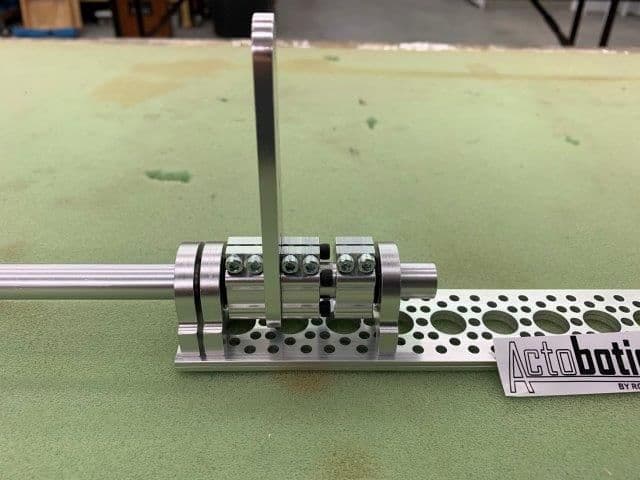
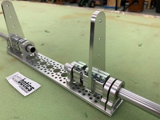
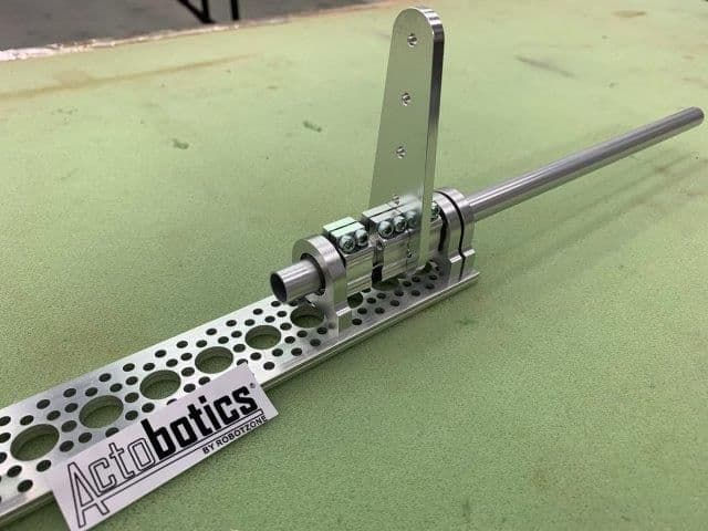
The clamp hub screws are at the rear to remove the stab tube from the rear if needed. Access is available by pulling the magnet fastened tail cone off the rear of the fuse. There are nylon separation washers between the bearing blocks and the clamp hubs. The rotation motion is very smooth and friction free.
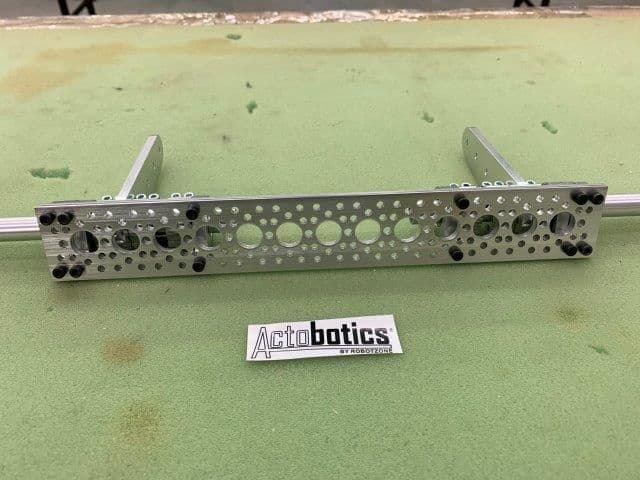
Bearing blocks are bolted to the bottom plate. This whole assembly will be bolted to a 1/4" ply floor glued between two existing rear fuse formers.
UPS also delivered the wing spar aluminum plate today but it was too late to get a photo. More to come...
Parts mocked up for the proposed stab drive layout. The exhaust pipe will dip down between the two stab drive tubes in the rear fuse area.
Only two mods needed so far. The control horns are too long and will be shortened and the tubes are of unknown material and have too thin of a wall. I will replace them with a known alloy and thicker wall tubing.
All parts bolt together with 6-32 bolts. I plan on two bearing blocks at the end of the base plate to better handle the stab air loads. Also I'm using a double base plate to get more strength and stiffness.
Control horns are too long and will be cut down.
The clamp hub screws are at the rear to remove the stab tube from the rear if needed. Access is available by pulling the magnet fastened tail cone off the rear of the fuse. There are nylon separation washers between the bearing blocks and the clamp hubs. The rotation motion is very smooth and friction free.
Bearing blocks are bolted to the bottom plate. This whole assembly will be bolted to a 1/4" ply floor glued between two existing rear fuse formers.
UPS also delivered the wing spar aluminum plate today but it was too late to get a photo. More to come...
Last edited by Viper1GJ; 01-04-2019 at 04:54 PM.
01-04-2019, 05:35 PM
#237
Thread Starter
My Feedback: (20)
I'm a lot more comfortable with the new plans for the main wing spar. I really appreciate the help with Paul's calculations and material selection. I was way off with my first idea. Also the TLAR observation mentioned by Jeremy I had not considered. I will enlarge the existing hole to allow air to pass over and under the spar plate but the plywood former will still bear some wing loads and will add a lot to the new aluminum spar plate.
The forum is really great for sharing ideas. Thanks again for everyone's recommendations, suggestions, and participation.
Gary
The forum is really great for sharing ideas. Thanks again for everyone's recommendations, suggestions, and participation.
Gary
01-05-2019, 05:57 PM
#238
Thread Starter
My Feedback: (20)
I opened the package for the spar plate and found out the piece of aluminum they sent was warped and curved and unusable. I will send it back and try again next week. However the 1/4" plate was massive and heavy. I am considering going to .19" (3/16") metal. I think with Paul's numbers and the existing plywood former bolts it will work OK.
01-05-2019, 06:03 PM
#239
Thread Starter
My Feedback: (20)
I started working on stab system.
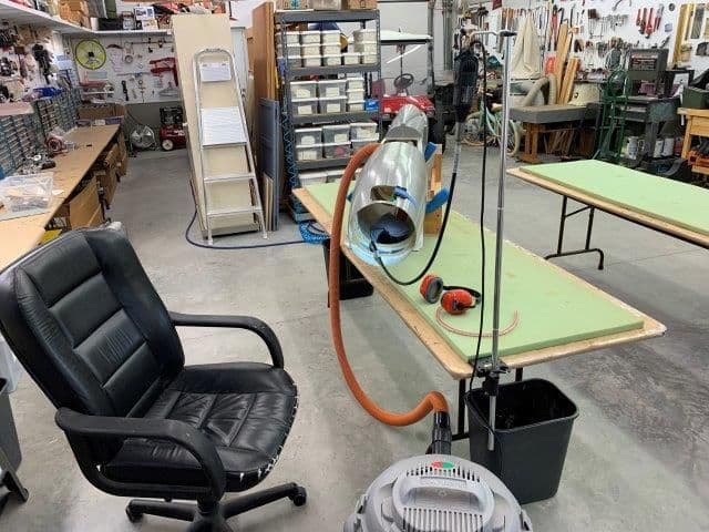
I set up the "dental office" to cut out the rear formers.
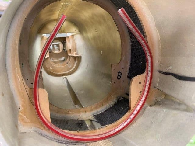
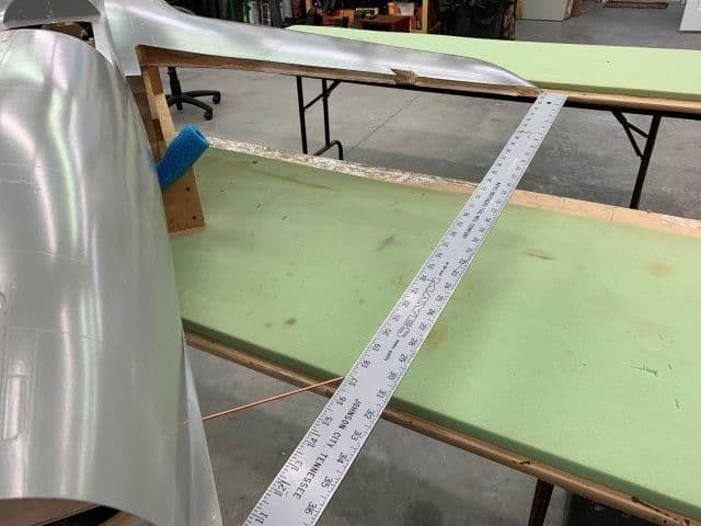
Marked the cutouts with a flexible ruler
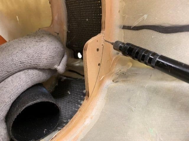
Dremel flex tool and thin router bit used to make cuts in plywood
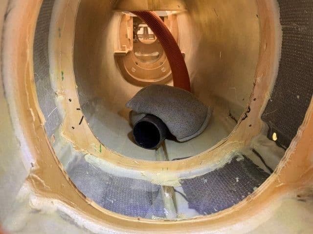
Rough cuts complete, vacuum hose sucked up dust
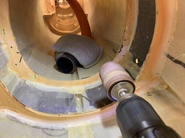
Sanding drum cleaned up router bit cuts
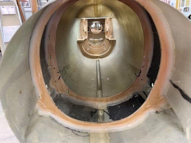
Formers sanded smooth and ready for stab floor fitting
I set up the "dental office" to cut out the rear formers.
Marked the cutouts with a flexible ruler
Dremel flex tool and thin router bit used to make cuts in plywood
Rough cuts complete, vacuum hose sucked up dust
Sanding drum cleaned up router bit cuts
Formers sanded smooth and ready for stab floor fitting
01-05-2019, 06:26 PM
#240
Thread Starter
My Feedback: (20)
The next step was to plot the pivot point of the stab and mark it on the fuse for the new stab pivot tube.
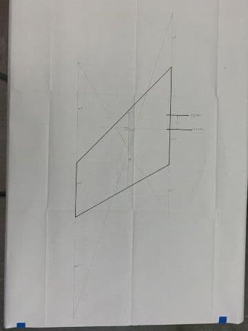
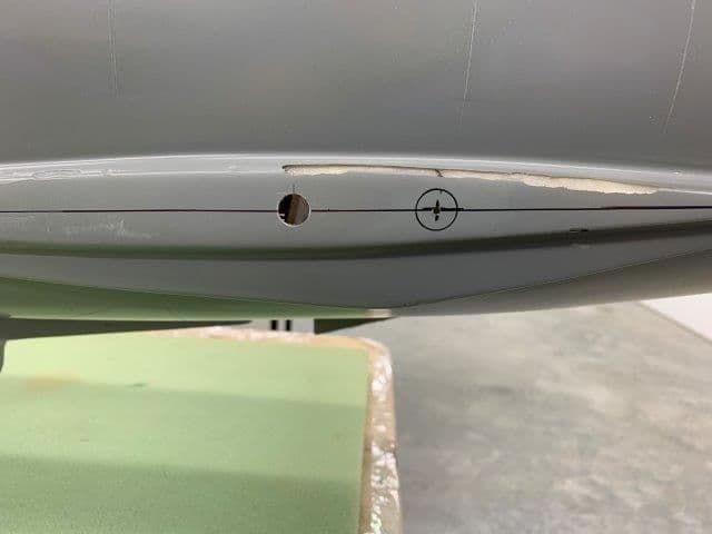
I used the diagram method in the AMA LMA document to find the stab MAC and plot out 23% MAC for the stab pivot point. My numbers came close to what I did before. The existing pivot rod is at about 5% MAC and way to far forward. The new pivot point will be 23% MAC per AMA LMA recommendation and be 1.8" aft of the existing pivot rod.
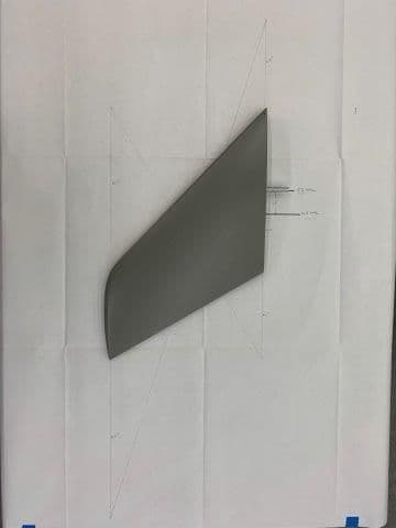
New vs old pivot points
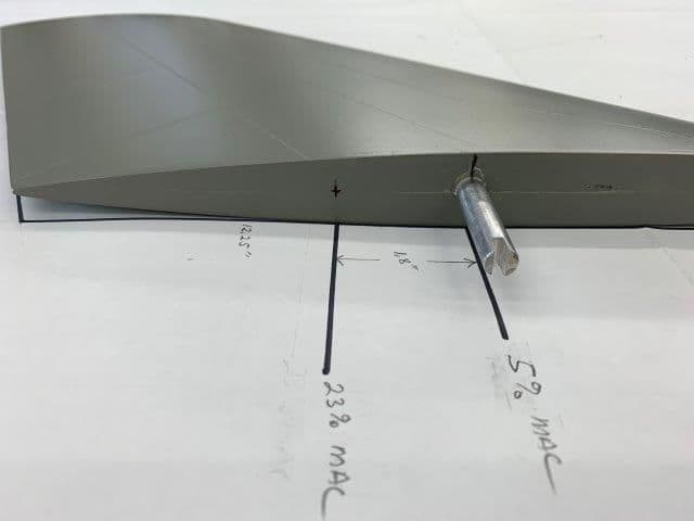
The new pivot point is marked 1.8" aft of the current pivot rod
These measurements were plotted on the fuse side.
I used the diagram method in the AMA LMA document to find the stab MAC and plot out 23% MAC for the stab pivot point. My numbers came close to what I did before. The existing pivot rod is at about 5% MAC and way to far forward. The new pivot point will be 23% MAC per AMA LMA recommendation and be 1.8" aft of the existing pivot rod.
New vs old pivot points
The new pivot point is marked 1.8" aft of the current pivot rod
These measurements were plotted on the fuse side.
01-05-2019, 06:48 PM
#241
Thread Starter
My Feedback: (20)
Next step is to fabricate a tray that will lay between the 2 rear fuse formers for the stab bearing blocks to bolt to
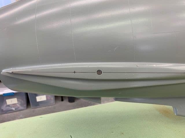
New stab pivot point drilled on each side of fuse and a straight wire inserted
The wire gives a reference to where the stab tubes will be inside the fuse and can be used to determine where the stab tray has to be located
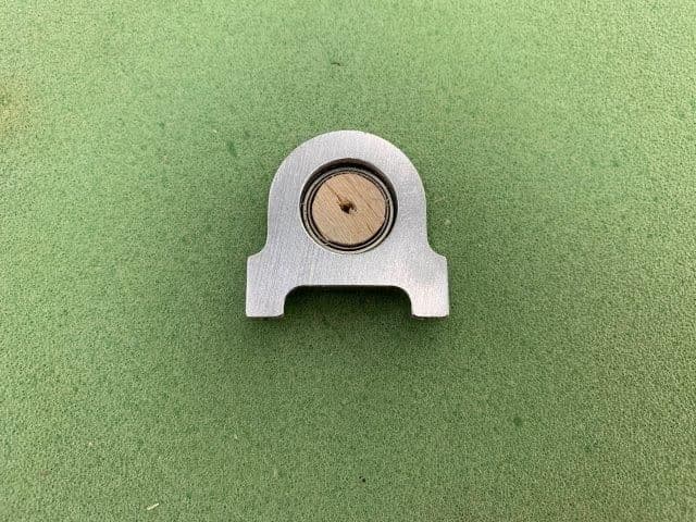
Balsa plug in bearing block allows it to hang on wire and allow marking of the base of the bearing block in fuse
The bottom of the bearing block marks the top of the aluminum base and stab tray
Next a piece of fan fold foam used to mock up the stab tray
A 3/4" ply block for the bearing block height and 3/16" balsa for aluminum base height sets the level for the stab tray. Next is to fabricate the plywood stab tray.
New stab pivot point drilled on each side of fuse and a straight wire inserted
The wire gives a reference to where the stab tubes will be inside the fuse and can be used to determine where the stab tray has to be located
Balsa plug in bearing block allows it to hang on wire and allow marking of the base of the bearing block in fuse
The bottom of the bearing block marks the top of the aluminum base and stab tray
Next a piece of fan fold foam used to mock up the stab tray
A 3/4" ply block for the bearing block height and 3/16" balsa for aluminum base height sets the level for the stab tray. Next is to fabricate the plywood stab tray.
01-06-2019, 04:42 PM
#242
Thread Starter
My Feedback: (20)
More thoughts on the wing spar...
I was unhappy with the 1/4" spar plate after seeing how much it weighed and how much wasted material and weight was at the outer ends where the thickness was not needed. I thought about using 3/16" material as a compromise way to save weight and I consulted with Paul by email about the idea. He ran the numbers and said it would work. However, he gave me a new recommendation to think about. He suggested using two pieces of 1/8" plate laminated together in the center section where the strength is needed but not the full length of the spar.
Inside the root wing rib the existing aluminum spar is doubled by a �” ply spar. There would be no need to extend the short piece of the doubled 1/8” spar plate inside the wing past the first set of bolt holes. The short piece would be securely bolted to the longer piece by 2 bolts inside the fuse and 2 bolts inside each wing on each side for a total of 8 bolts. The long piece would extend all the way out to the outer bolt holes in each wing. This would eliminate the weight where the double layer is not needed.
It may be possible to epoxy the pieces together after they are fabricated so that they act as one part to make it easier to align holes and insert bolts during assembly. I’m sure the 1/8” material would be easier to cut and shape and possibly allow air holes in the center if needed later.
Thanks again for the ideas.
Gary
01-06-2019, 05:10 PM
#244
Thread Starter
My Feedback: (20)
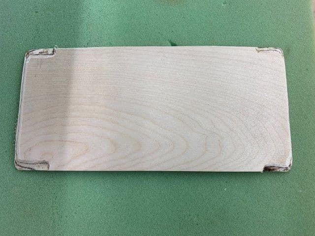
Continued working on stab tray. A 1/4" ply tray cut and fit for the stab bearings.
Wood stab tray fabricated and dry fit. Line under wire is center line of bearing block base.
I noticed the line was not straight across the wood tray so I decided to check if the wire was square with the fuse.
I mounted the wings and centered the wire in the fuse, then measured from each wing tip. To my complete surprise and astonishment the measurements were exactly the same one each side. The reason the line was not square was the formers are not installed square to the fuse center line. No surprise there.
1/2" hole marked on fuse side and drilled.
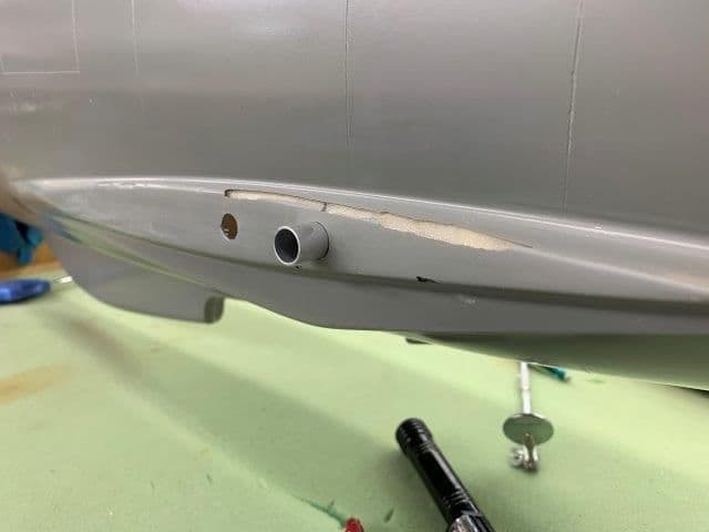
1/2" stab tube inserted through each hole.
Bottom of stab tray after an hour of cut, fit, cut, fit, cut, cut, fit etc, etc.
Stab tray finally at the proper level to mount the bearing blocks on the aluminum strips.
Right side was the most problem but finally got it to the correct level.
Wood stab tray fabricated and dry fit. Line under wire is center line of bearing block base.
I noticed the line was not straight across the wood tray so I decided to check if the wire was square with the fuse.
I mounted the wings and centered the wire in the fuse, then measured from each wing tip. To my complete surprise and astonishment the measurements were exactly the same one each side. The reason the line was not square was the formers are not installed square to the fuse center line. No surprise there.
1/2" hole marked on fuse side and drilled.
1/2" stab tube inserted through each hole.
Bottom of stab tray after an hour of cut, fit, cut, fit, cut, cut, fit etc, etc.
Stab tray finally at the proper level to mount the bearing blocks on the aluminum strips.
Right side was the most problem but finally got it to the correct level.
01-06-2019, 05:19 PM
#245
Thread Starter
My Feedback: (20)
I had not considered carbon fiber plate. I did not know it would be stronger that aluminum. I think it would be lighter for sure. Is there any data available for how strong it is compared to aluminum?
I need a piece 3" x 17.5" Any good source for a small amount?
I was planning on shims for mounting to wing spar in the wheel well.
Last edited by Viper1GJ; 01-06-2019 at 05:56 PM.
01-07-2019, 01:08 AM
#246

Viper - Carbon is a great option (it's the route I'd go down over ali or wood) but not all composite plate is equal. Just make sure you use something of high quality from a good supplier. I might be right in thinking Oli might be able to supply?
01-07-2019, 06:11 AM
#247
Gary,
Carbon is certainly way more expensive than Al. Are you that desperate to save a few ounces?
Consider uni-directional carbon for spars to get the optimum strength. Woven fabric layups won't give you the strength in the correct direction.
Look here, they will even cut it for you if you send them a drawing;
https://dragonplate.com/0-Degree-Car...3_16-x-12-x-24
Treating carbon fiber as a black metal (as aerospace did in the early days), from what I can see, it looks like uni-direction carbon is around 4 times as strong (Yield strength) as 7075, but carbon is more susceptible to damage.
An 1/8" thick solid uni-directional carbon version of your Al spar would probably be sufficient, but I'm not comfortable making a recommendation...........
Paul
01-07-2019, 07:09 AM
#248
Gary,
Carbon is certainly way more expensive than Al. Are you that desperate to save a few ounces?
Consider uni-directional carbon for spars to get the optimum strength. Woven fabric layups won't give you the strength in the correct direction.
Look here, they will even cut it for you if you send them a drawing;
https://dragonplate.com/0-Degree-Car...3_16-x-12-x-24
Treating carbon fiber as a black metal (as aerospace did in the early days), from what I can see, it looks like uni-direction carbon is around 4 times as strong (Yield strength) as 7075, but carbon is more susceptible to damage.
An 1/8" thick solid uni-directional carbon version of your Al spar would probably be sufficient, but I'm not comfortable making a recommendation...........
Paul
Carbon is certainly way more expensive than Al. Are you that desperate to save a few ounces?
Consider uni-directional carbon for spars to get the optimum strength. Woven fabric layups won't give you the strength in the correct direction.
Look here, they will even cut it for you if you send them a drawing;
https://dragonplate.com/0-Degree-Car...3_16-x-12-x-24
Treating carbon fiber as a black metal (as aerospace did in the early days), from what I can see, it looks like uni-direction carbon is around 4 times as strong (Yield strength) as 7075, but carbon is more susceptible to damage.
An 1/8" thick solid uni-directional carbon version of your Al spar would probably be sufficient, but I'm not comfortable making a recommendation...........
Paul
Bob
01-07-2019, 07:15 AM
#249
Good point Bob, a lot to consider for a good CF design.
Dragon have other options too;
0/ 90deg layup;
https://dragonplate.com/0_90-Degree-...3_16-x-12-x-24
Quasi-Isotropic
https://dragonplate.com/Quasi-isotro...3_16-x-12-x-24
Paul
Dragon have other options too;
0/ 90deg layup;
https://dragonplate.com/0_90-Degree-...3_16-x-12-x-24
Quasi-Isotropic
https://dragonplate.com/Quasi-isotro...3_16-x-12-x-24
Paul
01-07-2019, 03:58 PM
#250

I personally dont like carbon parts for wing attachments that have landing gear mounted in the wings. I�ve seen shock loads imparted into CF parts delaminate and/or crack and it not be noticed until the part failed.
I would much rather use and suffer from a slightly heavier/beefier piece of metal that will just bend.
Thats just my personal preference though.
I would much rather use and suffer from a slightly heavier/beefier piece of metal that will just bend.
Thats just my personal preference though.