


1/6 F-105 Build Thread
 12-14-2018, 02:57 PM
#201


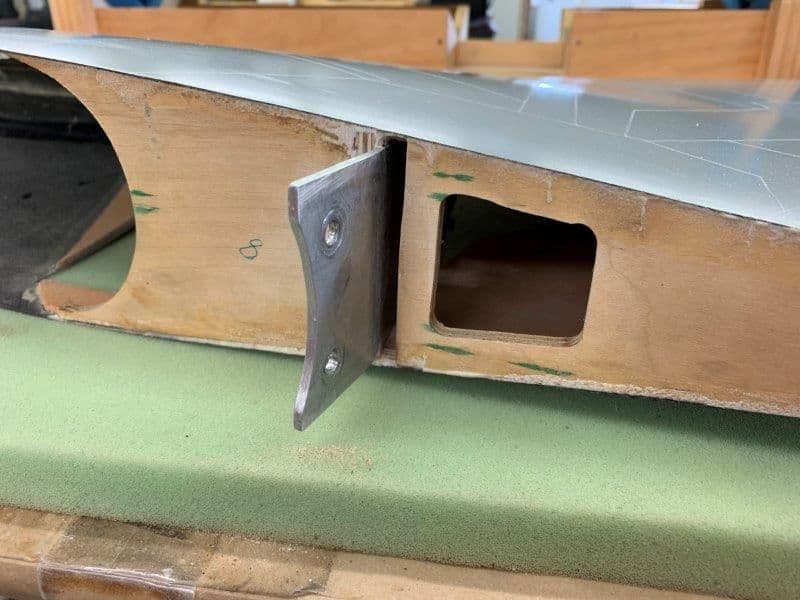
So the only structural spar that goes into the fuse is that short aluminum one with 2 bolts? That seems like an awful lot of load at just the root of the wing. I'd be awfully gentle on turns and any G loads until its flown a number of times and everything is pulled apart and checked for stress cracks. Just my opinion.
 12-14-2018, 07:03 PM
#202

Thread Starter
My Feedback: (20)
Hi Paul, Yes that could work but would take some more engineering and fabrication. My bigger concern is what Jeremy mentioned about the load bearing capability of the thin spar tab and plywood former.
Yes Jeremy, that's is the only spar. Its kind of like building a mansion on sand. Its the core foundation of the whole jet and I am having less and less confidence in it every time I assemble the thing and as it gets heavier. As I mentioned before I was considering ways to beef up the wing former. Also as I'm getting into the wings I am now considering ways to add some "beef" to the aluminum spar tab. My first thought is to double it but any new material will have to be on the back side of the wing former and the aluminum spar is on the front of the wing plywood spar. I'll have to see if its possible to add some more aluminum some way with out having to redesign and rebuild the whole system. I really don't want to do that.
Yes Jeremy, that's is the only spar. Its kind of like building a mansion on sand. Its the core foundation of the whole jet and I am having less and less confidence in it every time I assemble the thing and as it gets heavier. As I mentioned before I was considering ways to beef up the wing former. Also as I'm getting into the wings I am now considering ways to add some "beef" to the aluminum spar tab. My first thought is to double it but any new material will have to be on the back side of the wing former and the aluminum spar is on the front of the wing plywood spar. I'll have to see if its possible to add some more aluminum some way with out having to redesign and rebuild the whole system. I really don't want to do that.
12-15-2018, 08:21 AM
#203
The thickness of that aluminum spar isnt so much what my concern would be, it's more that so little of it slides into the fuse. The BVM super bandit blade spar was about 3" long and that was a smaller jet. It also had 3 bolts distributing the load over a longer distance. I'd feel better if that blade spar was longer and slid into a receptical. If nothing else, because of how I am understanding the wing goes on (it has to slide forwards as it goes inwards?) I would glue and bolt and aluminum rail onto the fuse bulkhead above and below that spar so when it slides in it is engaged by something solid both top and bottom rather than relying on two bolts to keep it from flexing up and down. The bolts should be for retention only, there should be some type of rail to help keep it from flexing.
just my thoughts.
just my thoughts.
12-15-2018, 08:25 AM
#204
As for the rear bolts, rather than have to angle them in over the turbine and remove that former bridge, do the flaps drop far enough that the blind nut could be inside the fuselage and the bolts be inserted from the outside, through the wing root with the flap dropped down?
12-15-2018, 10:16 AM
#206

Why not just connect the main spar with a bridge? Yes you give up a full bypass but who cares, the strength you gain from connecting them would be worth it IMO. Additionallly, you could still use a “ shortened intake to bypass “ to direct air to turbine and ads a FOD screen to protect the motor from flying debris etc.
have fun fun with princess birthday party
have fun fun with princess birthday party
12-15-2018, 11:39 AM
#207
Why not just connect the main spar with a bridge? Yes you give up a full bypass but who cares, the strength you gain from connecting them would be worth it IMO. Additionallly, you could still use a � shortened intake to bypass � to direct air to turbine and ads a FOD screen to protect the motor from flying debris etc.
have fun fun with princess birthday party
have fun fun with princess birthday party
I was thinking similarly Buck but not so much with a bridge added in. That spar is removable. I would personally make new spars that go better than half way through the fuse and fit into a sleeve to connect them. I'll draw a picture Haha.
 12-15-2018, 05:14 PM
#210
Thread Starter
My Feedback: (20)
Birthday party Under The Sea theme done. Shop and jets survived. Back to work after cleanup.
Me standing off to side in Storm Trooper armor saying to any nearby 9yr olds, "nothing to see here, just move along"
Grandaughter and friend finishing off whats left of seahorse pinata

The aftermath...
Me standing off to side in Storm Trooper armor saying to any nearby 9yr olds, "nothing to see here, just move along"
Grandaughter and friend finishing off whats left of seahorse pinata
The aftermath...
 12-15-2018, 05:25 PM
#212
12-15-2018, 06:06 PM
#213
Thread Starter
My Feedback: (20)
Man, I love this forum. You guys are awesome.
I saw the last posts just after the birthday party was over and waiting for everyone to leave. You guys got me to think out side the box I've been stuck in since I started this project. From day one I've been worried about the wing spar design. It may have worked on a lighter plane but I expect this one to be over 60 lbs. IMO there is just no way a short spar tab and two bolts into plywood would work. I'm sure it will see 4-6Gs in just normal flying plus landing shock loads. I just kept trying to improve a bad design. The last posts got me to change paradigm on how to mount the wings. Many thanks to all. Please keep the suggestions flowing. I can use all the help I can get on this thing.
My new idea is to have a continuous aluminum spar completely through the fuse extending out about 4" into each wing. It would bolt to the wing with the existing bolts that attach the current aluminum spar to the plywood wing spar in the wheel well. The 1st photo in post #196 shows these bolts. My idea is to add a 1/8" aluminum plate that will extend all the way across the fuse to the other wing. The existing bolts and spar tabs in the fuse would be just to attach the wing spar to the fuse, not to bear all the wing loads. Those loads would be transferred from the wing to the main spar through the 4 bolts in the gear well, supported completely thru the fuse and then into the other wing the same way. This way there is a solid one piece aluminum spar from wing to wing and does not rely at all on the plywood wing former to bear wing loads. The former is just there to hang the wing structure on to the fuse.
I can make some lightening holes in the spar as it crosses the main air hole to allow some air to flow through the spar to the turbine. Also since the plywood wing former is no longer supporting the entire wing loads, I can widen the hole at the bottom and allow more air through there. I was not planning to use a bypass at all so I have to have enough air flow to support a 300N turbine.
The install would take more steps but it probably would not fail in flight. I would slide the new spar plate through the fuse then slide each wing on. Then you would install the bolts inside the fuse and the bolts in each wheel well. I also like the idea of inserting the lateral trailing edge bolts from the flap side into a blind nut inside the fuse. Would be much easier and no off angle ball driver needed.
What are your opinions of this wing spar design idea? Again, many thanks for all the ideas, recommendations, and suggestions.
Gary
12-16-2018, 08:00 AM
#214

The spar sounds way stronger and to ease assembly at the field, surely you could leave the spar permanently attached in one wing, slide that one on and then do up the bolts in the gear well of the other wing once it's on?
Probably won't be any more hassle to put together than an old super bandit
Probably won't be any more hassle to put together than an old super bandit
12-16-2018, 10:21 AM
#215
Or F4 or F100....I think you’re on the right track regarding the new continuous wing to wing spar. These motors don’t need a huge amount of air but I’m sure there’s a smart guy on here who can compute the air intake required to feed it.
Oh yeah...I want to play in that shop too. Lol
Oh yeah...I want to play in that shop too. Lol
12-16-2018, 04:59 PM
#216
Just to play devil's advocate here:
the SM f16 uses a plywood-carbon-plywood sandwich former to join the 2 fairly short carbon cylinders sticking out of the 2 wing halves and support all wing loads. I got this plane broken in half by a friend and, after repairing it, I did a static load test for over 7g and it passed with flying colors.
Before re-engineering yours, you may want to consider doing the same and do a static load test, it's very easy and can give you a clearer picture of where you stand at with the current design.
12-16-2018, 06:28 PM
#217
Thread Starter
My Feedback: (20)
One complication with the aluminum cross spar is that the wing has anhedral and its not quite a simple as a straight piece of aluminum across the fuse. Also access to bolt the the spars into the wings is a problem. I'll have to look more closely once I get the shop set up again.
Thanks for all the suggestions,
Gary
Thanks for all the suggestions,
Gary
12-16-2018, 07:18 PM
#218
with anhedral in the wings this would likely be the most viable solution then unless you can install a permanent spar on through the fuse but if access through the wing is tough this might be easiest. Truth is if you have rails that capture the spars you probably dont even need to bolt the spars in the fuse if you have bolts that go through the root.
12-16-2018, 07:21 PM
#219
Just to play devil's advocate here:
the SM f16 uses a plywood-carbon-plywood sandwich former to join the 2 fairly short carbon cylinders sticking out of the 2 wing halves and support all wing loads. I got this plane broken in half by a friend and, after repairing it, I did a static load test for over 7g and it passed with flying colors.
Before re-engineering yours, you may want to consider doing the same and do a static load test, it's very easy and can give you a clearer picture of where you stand at with the current design.
the SM f16 uses a plywood-carbon-plywood sandwich former to join the 2 fairly short carbon cylinders sticking out of the 2 wing halves and support all wing loads. I got this plane broken in half by a friend and, after repairing it, I did a static load test for over 7g and it passed with flying colors.
Before re-engineering yours, you may want to consider doing the same and do a static load test, it's very easy and can give you a clearer picture of where you stand at with the current design.
F16 has a much shorter span wing, way more of a lifting fuselage, and no shock loads transmitted through the gear into the wing into the joiners. What is adequate for an F16 wing is not going to be the same for something like the 105 imo
12-21-2018, 05:17 PM
#220
Thread Starter
My Feedback: (20)
It's been hard to get shop time this week. Grand kids school events, Christmas prep, errands, etc etc. I spent about an hour staring at the wing spars today trying to figure the best way to make a cross spar and mount it. I got some 1/4-20 clamp bolts with a 1" plastic knurled knob on top to test mounting the wings with out any tools. They may work. I plan to figure out the wing spar system before I do anything else since its the foundation of the whole project. I will post more pics as I make some progress. Thanks for all the ideas and help.
Merry Christmas,
Gary
Merry Christmas,
Gary
12-28-2018, 05:10 PM
#221
Thread Starter
My Feedback: (20)
Got a couple of hours of shop time after Christmas and was able to fabricate a wood pattern for the aluminum cross spar.
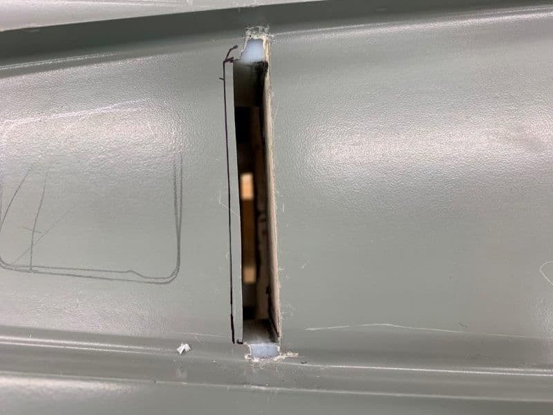
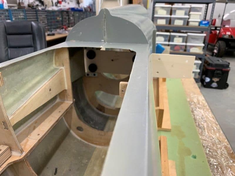
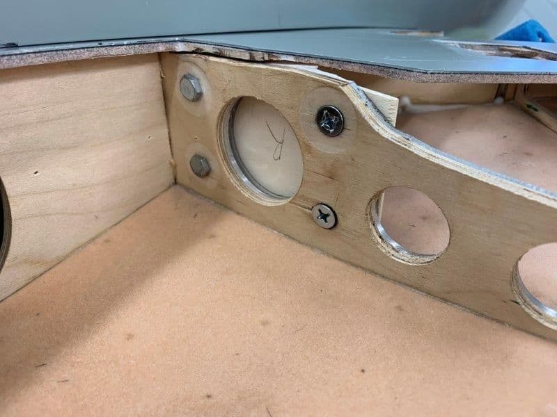
First step was to widen the spar slot in the fuse as shown marked to rear of slot.
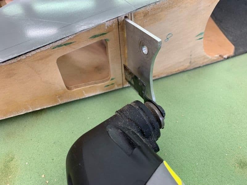
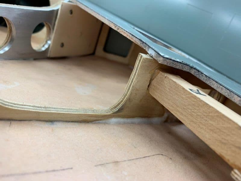
Next was to open a spar slot on the 1/4" ply wing root rib with dremel saw.
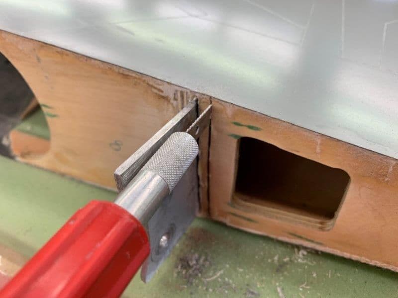
Final cuts on edges with Xacto hand saw
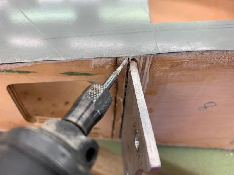
Top cuts with dremel rotary tool and small router bit
Finished slot
First step was to widen the spar slot in the fuse as shown marked to rear of slot.
Next was to open a spar slot on the 1/4" ply wing root rib with dremel saw.
Final cuts on edges with Xacto hand saw
Top cuts with dremel rotary tool and small router bit
Finished slot
12-28-2018, 05:26 PM
#222
Thread Starter
My Feedback: (20)
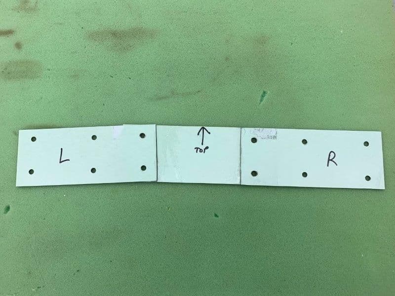
Next a stiff cardboard file divider was used to make templates for each wing spar section
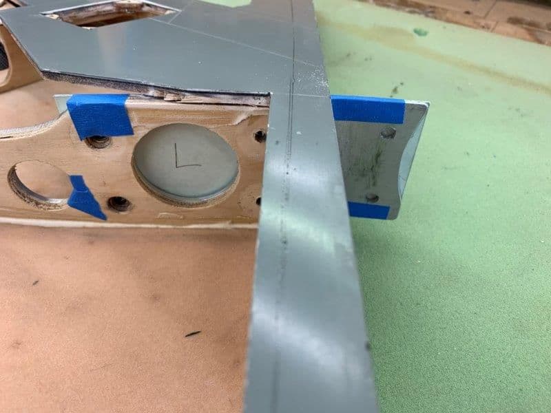
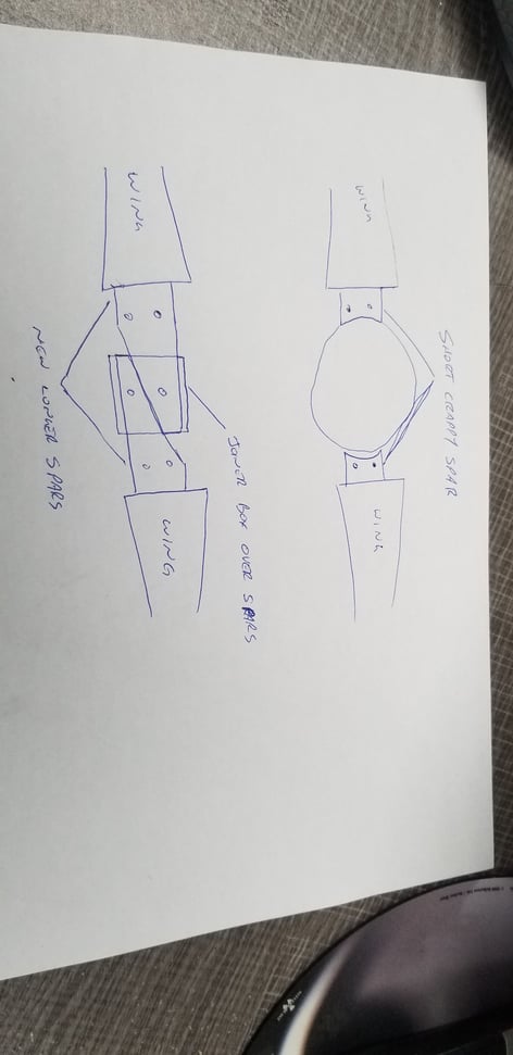
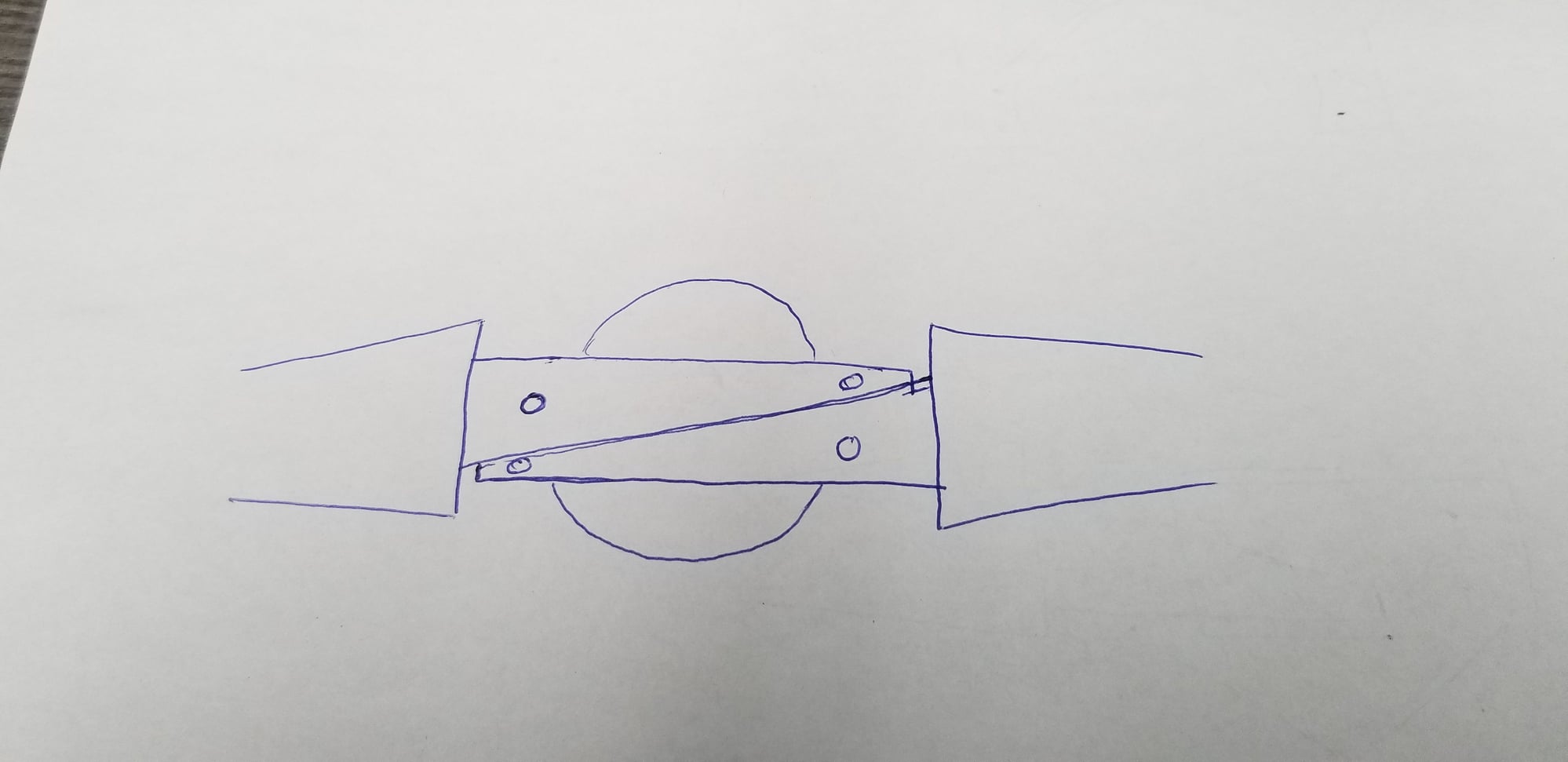
Left and right wing section templates made and holes marked. The new spar will extend about 5" into each wing and be secured with the existing 1/4-20 bolts that hold the aluminum spar tab to the 1/4" ply wing spar.
 \
\
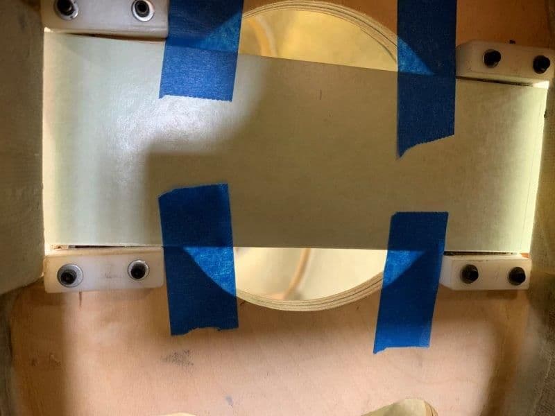
A center section was made to bridge across the fuse. Intake cutout and wing mounting holes were marked and drilled.
Next step was to mount the wings with the overlapping cardboard templates. I used 1/4-20 knurled thumb screws to test if they would work. Seems OK so far.
While the wings were mounted I epoxied the cardboard template sections together to form one cross template.
This is the initial shape of the template. Like everything else in this pile of parts nothing lines up.
Left and right wing section templates made and holes marked. The new spar will extend about 5" into each wing and be secured with the existing 1/4-20 bolts that hold the aluminum spar tab to the 1/4" ply wing spar.
\A center section was made to bridge across the fuse. Intake cutout and wing mounting holes were marked and drilled.
Next step was to mount the wings with the overlapping cardboard templates. I used 1/4-20 knurled thumb screws to test if they would work. Seems OK so far.
While the wings were mounted I epoxied the cardboard template sections together to form one cross template.
This is the initial shape of the template. Like everything else in this pile of parts nothing lines up.
12-28-2018, 05:39 PM
#223
Thread Starter
My Feedback: (20)
The cardboard template was transfered to a piece of light plywood and all holes marked and drilled.

The spar will extend into each wing about 5"
It goes all the way across the fuse and extends into the other wing.
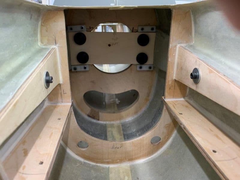
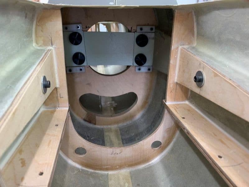
Now the only function of the wing former is to hang the wing onto the fuse. The wing loads are now supported by the cross spar and are no longer supported by the plywood. The spar is easy to slide into place and install the thumb bolts. Since the wing loads are no longer all carried by wing former I plan to enlarge the existing air inlet hole so that there is more open area above and below the spar to allow adequate air to the turbine.
The new spar will bolt to each wing with existing bolt holes. So far there seems to be adequate access to bolt the wings on the new spar.
View from wheel well
The spar will extend into each wing about 5"
It goes all the way across the fuse and extends into the other wing.
Now the only function of the wing former is to hang the wing onto the fuse. The wing loads are now supported by the cross spar and are no longer supported by the plywood. The spar is easy to slide into place and install the thumb bolts. Since the wing loads are no longer all carried by wing former I plan to enlarge the existing air inlet hole so that there is more open area above and below the spar to allow adequate air to the turbine.
The new spar will bolt to each wing with existing bolt holes. So far there seems to be adequate access to bolt the wings on the new spar.
View from wheel well
Last edited by Viper1GJ; 12-28-2018 at 05:44 PM.
12-28-2018, 06:29 PM
#224
Thread Starter
My Feedback: (20)
This is where I need some advice from some smart guys.
I plan to make some holes to allow more air through the spar and to reduce weight. How thick of material and how big the holes in the middle is the question.
I plan to use 7075 aluminum plate for the cross spar. I can use .125" (1/8") or .16 (5/32"). Which would be best? Is the 1/8" good enough or do you get a stronger spar with the 5/32" worth the weight penalty? 1/8" would be easier to work with and cheaper.
Based on my calculations the spar covers about 60% of the existing air inlet in the former. I plan to enlarge the inlet hole above and below the spar to get some air flow area back.
The outer lightening holes drawn on the wood template are the same size as the existing holes in the wood and aluminum spars in the wings. I can make these holes smaller on the new aluminum spar if more metal is needed around the outside mounting holes.
I don't know much about how the wing forces will act on a spar that looks like this with the existing mounting holes, I can only use the old TLAR method but sometimes that has hidden hazards for the uneducated. I made three design concepts and need suggestions. Thanks in advance for the suggestions and recommendations.
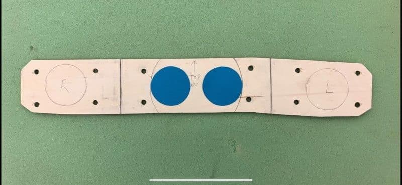
Two 2" holes give the most open area back but leave the least amount of metal on top and bottom of spar in the center section and are closer to the inside mounting holes . They give me back about 33% of the air inlet.
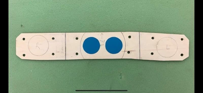
Two 1 3/4" holes evenly spaced between the top and bottom and the inside mounting holes give me back about 25% of the air inlet and gives a little more metal at the top and bottom of the center section.
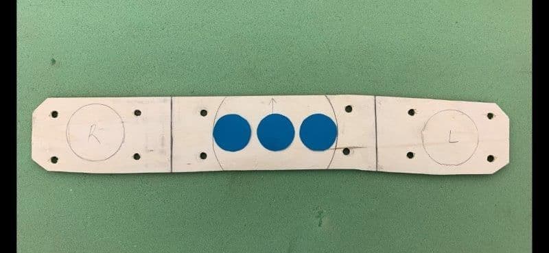
Three 1 3/8" holes evenly spaced across the air inlet hole gives me back about 23% of the air inlet and has the most metal at the top and bottom of the center section but are closer to the inside mounting holes. It looks like a truss of sorts.
Which concept would be best or did I miss the mark entirely?
Thanks,
Gary
I plan to make some holes to allow more air through the spar and to reduce weight. How thick of material and how big the holes in the middle is the question.
I plan to use 7075 aluminum plate for the cross spar. I can use .125" (1/8") or .16 (5/32"). Which would be best? Is the 1/8" good enough or do you get a stronger spar with the 5/32" worth the weight penalty? 1/8" would be easier to work with and cheaper.
Based on my calculations the spar covers about 60% of the existing air inlet in the former. I plan to enlarge the inlet hole above and below the spar to get some air flow area back.
The outer lightening holes drawn on the wood template are the same size as the existing holes in the wood and aluminum spars in the wings. I can make these holes smaller on the new aluminum spar if more metal is needed around the outside mounting holes.
I don't know much about how the wing forces will act on a spar that looks like this with the existing mounting holes, I can only use the old TLAR method but sometimes that has hidden hazards for the uneducated. I made three design concepts and need suggestions. Thanks in advance for the suggestions and recommendations.
Two 2" holes give the most open area back but leave the least amount of metal on top and bottom of spar in the center section and are closer to the inside mounting holes . They give me back about 33% of the air inlet.
Two 1 3/4" holes evenly spaced between the top and bottom and the inside mounting holes give me back about 25% of the air inlet and gives a little more metal at the top and bottom of the center section.
Three 1 3/8" holes evenly spaced across the air inlet hole gives me back about 23% of the air inlet and has the most metal at the top and bottom of the center section but are closer to the inside mounting holes. It looks like a truss of sorts.
Which concept would be best or did I miss the mark entirely?
Thanks,
Gary
Last edited by Viper1GJ; 12-28-2018 at 06:36 PM.
12-28-2018, 06:45 PM
#225
Gary,
Is the aluminum spar going to be removable from the fuselage, i.e., does it need to slide in and out?
If it has to slide in and out and that is the shape you need, I'd go with the larger holes and use the heavier material. I don't think the 1/8" material is strong enough for this application.
Bob
Is the aluminum spar going to be removable from the fuselage, i.e., does it need to slide in and out?
If it has to slide in and out and that is the shape you need, I'd go with the larger holes and use the heavier material. I don't think the 1/8" material is strong enough for this application.
Bob