


s/m 1/6 f16 in my hot little hands!

 10-18-2017, 10:04 PM
#1902

My Feedback: (2)
Pushing on with my f16 and i must say I am rather disappointed with the quality of this kit...I am a bit baffled by the photos of the fuel tanks in this thread. I had to sand quite a bit of fuselage around the main hatch area to accommodate the center fuel tank supplied by skymaster. Even after opening the area around it its a very snug fit...in all photos in this thread there seems to be plenty of space around the tank, not so in my kit???
10-19-2017, 09:25 AM
#1904

Pushing on with my f16 and i must say I am rather disappointed with the quality of this kit...I am a bit baffled by the photos of the fuel tanks in this thread. I had to sand quite a bit of fuselage around the main hatch area to accommodate the center fuel tank supplied by skymaster. Even after opening the area around it its a very snug fit...in all photos in this thread there seems to be plenty of space around the tank, not so in my kit???
10-20-2017, 07:22 PM
#1906
Member
Join Date: Apr 2002
Location: Auckland, NEW ZEALAND
Posts: 86
Likes: 0
Received 0 Likes
on
0 Posts
Pushing on with my f16 and i must say I am rather disappointed with the quality of this kit...I am a bit baffled by the photos of the fuel tanks in this thread. I had to sand quite a bit of fuselage around the main hatch area to accommodate the center fuel tank supplied by skymaster. Even after opening the area around it its a very snug fit...in all photos in this thread there seems to be plenty of space around the tank, not so in my kit???
I emailed SM about 6 times on this subject and never broke through their rock solid wall of silence.
10-21-2017, 06:36 PM
#1907


Join Date: Oct 2013
Location: Bangkok, Thailand
Posts: 76
Likes: 0
Received 0 Likes
on
0 Posts
I cut my ducting to accommodate the larger main tank & I use the full bypass, no problems with the gear doors & stock rams. I replaced the Pneumatic nose tire with a solid BVM one because it wouldn't fit in the bay once inflated. Mains are inflated to a max dia of 103 mm.
The Skymaster kit does need a bit of "tailoring" but it all comes together well & fly's very well. The landing gear is amazingly robust.
One thing you will notice is the Elevons, or Elevators are not level once you've made your first flights, there will be a very large maybe 3/8 inch difference on the right in a nose up direction, this is normal, I'm not sure if the wings are twisted or if the fuselage is twisted, but it seems to be there on many of them.
10-22-2017, 07:34 AM
#1908
Join Date: Oct 2013
Location: Bangkok, Thailand
Posts: 76
Likes: 0
Received 0 Likes
on
0 Posts
Flew again today, just over two years since the Maiden flight. The power of the JB220 is phenomenal, but frankly it needs to be, this thing is HEAVY on take-off, needs lots of power to fly straight & level, at least 50% throttle to pull out of a dive, or she will pancake, you can switch to high alpha mode but thats a bit advanced.
Landing needs a high approach, speed brakes deployed, 50% throttle coming out of the final turn, high nose, balanced with the power & fly her all the way down, flare in ground effect, apply a little brake and roll to a stop an the runway to avoid a tip up.
I'd suggest anyone flying this aircraft needs to be very aware of the power requirements to make it fly, if in the turn you back off the throttle too much the nose will drop, of fall out of the groove, just keep the power on.
I'm kinda writing this for my self but wanted to share my thoughts.
I fly for a Minimum of 9 minutes before attempting a landing due to the excess fuel weight in the main tank.
10-22-2017, 11:10 AM
#1909
My Feedback: (3)

Join Date: Oct 2005
Location: san jose,
CA
Posts: 880
Likes: 0
Received 0 Likes
on
0 Posts
I've got a G1 that was built light, not using the stock center tank. Using a much smaller one. Sounds like it flies a bit different than what you describe but then I don't get that flight time. I think mine does 7 min but overall flies a bit lighter on a 180 and no bypass. Really like the way it flies this way.
10-22-2017, 10:45 PM
#1911
It will be even more fun when you put them in there plumbed together with the fuel lines and all safety wired, gotta go in just right.
Also pressure check and clean those tanks at least twice,,all 3 of mine had trash in em.
Also pressure check and clean those tanks at least twice,,all 3 of mine had trash in em.
Last edited by raron455; 10-22-2017 at 10:47 PM.
10-23-2017, 06:36 PM
#1913
Join Date: Oct 2013
Location: Bangkok, Thailand
Posts: 76
Likes: 0
Received 0 Likes
on
0 Posts
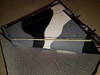
Hi Loukos, from the photo to looks like the saddle tanks are in upside down.
I had to epoxy the originals closed & cut new holes to miss the former on the FWD section. Otherwise the main tank is too high, resting on not much & when you pull G's it will split the FUS under the wing. Ask me how I know this.....
I had to epoxy the originals closed & cut new holes to miss the former on the FWD section. Otherwise the main tank is too high, resting on not much & when you pull G's it will split the FUS under the wing. Ask me how I know this.....
10-23-2017, 07:02 PM
#1914
Hi Loukos, from the photo to looks like the saddle tanks are in upside down.
I had to epoxy the originals closed & cut new holes to miss the former on the FWD section. Otherwise the main tank is too high, resting on not much & when you pull G's it will split the FUS under the wing. Ask me how I know this.....
I had to epoxy the originals closed & cut new holes to miss the former on the FWD section. Otherwise the main tank is too high, resting on not much & when you pull G's it will split the FUS under the wing. Ask me how I know this.....
I used BVM high flow tank hardware kits for my tanks, to make it easier.
I also got my saddle tanks in place, then made a ply mount and hysoled it to the bottom corner of the tanks, it sits flush against the main former on the sides, I then put a screw through the plate into the former holding those saddle tanks in place. Then I put Velcro on top of the saddles and on the bottom of the main upper tank, and put a piece of foil between them, slid the tank in and pulled the foil out, allowing the Velcro to latch and hold the main tank in place on top of the saddle tanks. If not they can shift around some.
Last edited by raron455; 10-23-2017 at 07:07 PM.
10-23-2017, 08:18 PM
#1915
My Feedback: (2)
Hi Loukos, from the photo to looks like the saddle tanks are in upside down.
I had to epoxy the originals closed & cut new holes to miss the former on the FWD section. Otherwise the main tank is too high, resting on not much & when you pull G's it will split the FUS under the wing. Ask me how I know this.....
I had to epoxy the originals closed & cut new holes to miss the former on the FWD section. Otherwise the main tank is too high, resting on not much & when you pull G's it will split the FUS under the wing. Ask me how I know this.....
Regards Luke
10-23-2017, 08:21 PM
#1916
My Feedback: (2)
Good catch Thai, Loukos those saddle tanks are in wrong,, My fittings also hit my formers, I sanded a curve in the former to clear the lines more than I wanted to, I also had to remove the small wood cross brace that goes across the fuse to be able to access all my lines and connections.
I used BVM high flow tank hardware kits for my tanks, to make it easier.
I also got my saddle tanks in place, then made a ply mount and hysoled it to the bottom corner of the tanks, it sits flush against the main former on the sides, I then put a screw through the plate into the former holding those saddle tanks in place. Then I put Velcro on top of the saddles and on the bottom of the main upper tank, and put a piece of foil between them, slid the tank in and pulled the foil out, allowing the Velcro to latch and hold the main tank in place on top of the saddle tanks. If not they can shift around some.
10-25-2017, 08:10 AM
#1917

Join Date: Mar 2004
Location: Oslo, NORWAY
Posts: 1,616
Likes: 0
Received 0 Likes
on
0 Posts
Flew again today, just over two years since the Maiden flight. The power of the JB220 is phenomenal, but frankly it needs to be, this thing is HEAVY on take-off, needs lots of power to fly straight & level, at least 50% throttle to pull out of a dive, or she will pancake, you can switch to high alpha mode but thats a bit advanced.
Landing needs a high approach, speed brakes deployed, 50% throttle coming out of the final turn, high nose, balanced with the power & fly her all the way down, flare in ground effect, apply a little brake and roll to a stop an the runway to avoid a tip up.
I'd suggest anyone flying this aircraft needs to be very aware of the power requirements to make it fly, if in the turn you back off the throttle too much the nose will drop, of fall out of the groove, just keep the power on.
I'm kinda writing this for my self but wanted to share my thoughts.
I fly for a Minimum of 9 minutes before attempting a landing due to the excess fuel weight in the main tank.
Landing needs a high approach, speed brakes deployed, 50% throttle coming out of the final turn, high nose, balanced with the power & fly her all the way down, flare in ground effect, apply a little brake and roll to a stop an the runway to avoid a tip up.
I'd suggest anyone flying this aircraft needs to be very aware of the power requirements to make it fly, if in the turn you back off the throttle too much the nose will drop, of fall out of the groove, just keep the power on.
I'm kinda writing this for my self but wanted to share my thoughts.
I fly for a Minimum of 9 minutes before attempting a landing due to the excess fuel weight in the main tank.
Yes, it was a bit more hazzle to put the tanks in - I fitted Festo couplings on all 3 tanks, then glued them in and put the tubing in last, around the formers.
Tor
 11-07-2017, 02:51 AM
#1919
Join Date: Mar 2004
Location: Oslo, NORWAY
Posts: 1,616
Likes: 0
Received 0 Likes
on
0 Posts
Hi Jon! On the gen 1 my CG was at 220 mm. Hope you are good and fly a lot - I recently sold my F-16, but am already regretting it... There will probably be another one in the future!
Tor
Tor
02-21-2018, 11:21 PM
#1920
My Feedback: (2)
Hi guys,
Working on the wings and have stumbled on quite a few issues, feedback welcome...
1. Leading edge Flaps (LEF) .
Pictures showing Antons post in this forum showing the LEF (tigermeet colour scheme). The Lip is extended to the wing skin . The LEF overlaps the wing skin. On my kit this is the other way around, i.e the lip is on the leading edge slat. this will mean the airflow will be flowing over the skin which will cause too much turbulent air and also may cause the wing skin to de-laminate with catastrophic consequences.
2. Also,on both wings with the LEF retracted, there is a big gap of 2-3mm between LEF and Wing Skin. This will again disrupt the airflow over the wing at normal and high speeds and also exert high pressure on the wing skin at that point.
3. BIGGER PROBLEM! - The carbon spar on BOTH wings are too short. They do not pass through the inner wing clamp mechanism. The result is that the wings do not secure accurately and safely to the fuselage!
Ideas??
02-22-2018, 07:59 AM
#1921
My Feedback: (3)
Join Date: Oct 2005
Location: san jose,
CA
Posts: 880
Likes: 0
Received 0 Likes
on
0 Posts
Couple thoughts on the wing rod/clamp. It looks like it catches it just enough but agree, disconcerting. How many others have same issue? Constraining the rod at that location is important for bending moment as well as securing the wing. I'd probably dremel the carbon out a bit(removing that amount of carbon is not going to alter what the carbon accomplishes which is a small amount of added stiffness, TLAR'd in that section of the wing root), move it over if there is access.
If no access, then you could do what we do on larger than this, IMAC and do a removable bolt to the wing root(secures from the inside). The wing root itself needs to have some thickness to take the threading of a 1/4-20.
Darren
If no access, then you could do what we do on larger than this, IMAC and do a removable bolt to the wing root(secures from the inside). The wing root itself needs to have some thickness to take the threading of a 1/4-20.
Darren
02-22-2018, 07:18 PM
#1922
Join Date: Mar 2005
Location: -, CHINA
Posts: 96
Likes: 0
Received 0 Likes
on
0 Posts
Hi guys,
Working on the wings and have stumbled on quite a few issues, feedback welcome...
1. Leading edge Flaps (LEF) .
Pictures showing Antons post in this forum showing the LEF (tigermeet colour scheme). The Lip is extended to the wing skin . The LEF overlaps the wing skin. On my kit this is the other way around, i.e the lip is on the leading edge slat. this will mean the airflow will be flowing over the skin which will cause too much turbulent air and also may cause the wing skin to de-laminate with catastrophic consequences.
2. Also,on both wings with the LEF retracted, there is a big gap of 2-3mm between LEF and Wing Skin. This will again disrupt the airflow over the wing at normal and high speeds and also exert high pressure on the wing skin at that point.
3. BIGGER PROBLEM! - The carbon spar on BOTH wings are too short. They do not pass through the inner wing clamp mechanism. The result is that the wings do not secure accurately and safely to the fuselage!
Ideas??
Working on the wings and have stumbled on quite a few issues, feedback welcome...
1. Leading edge Flaps (LEF) .
Pictures showing Antons post in this forum showing the LEF (tigermeet colour scheme). The Lip is extended to the wing skin . The LEF overlaps the wing skin. On my kit this is the other way around, i.e the lip is on the leading edge slat. this will mean the airflow will be flowing over the skin which will cause too much turbulent air and also may cause the wing skin to de-laminate with catastrophic consequences.
2. Also,on both wings with the LEF retracted, there is a big gap of 2-3mm between LEF and Wing Skin. This will again disrupt the airflow over the wing at normal and high speeds and also exert high pressure on the wing skin at that point.
3. BIGGER PROBLEM! - The carbon spar on BOTH wings are too short. They do not pass through the inner wing clamp mechanism. The result is that the wings do not secure accurately and safely to the fuselage!
Ideas??
we just sent mail to you.pls check.
Regards
John
skymaster
02-24-2018, 02:19 PM
#1924
Join Date: Feb 2018
Location: South of GERMANY
Posts: 1
Likes: 0
Received 0 Likes
on
0 Posts
Hi loukos,
i've got slat wings as well - same situation the lip is located on the slat:
regards
Torsten
i've got slat wings as well - same situation the lip is located on the slat:
regards
Torsten
Last edited by DerTausKA; 02-26-2018 at 02:01 AM. Reason: Correction
06-10-2018, 02:47 AM
#1925

Join Date: Jun 2006
Location: Gold Coast, Queensland, AUSTRALIA
Posts: 1,469
Received 26 Likes
on
24 Posts
Hi guys,
Can anyone confirm what cg they are using on a G2 version. The manual range is 200 to 220mm from where the wing leading edge meets the fuselage. Basically 200 is on the main removable spar brace that bolts into the fuselage and over the engine.
Thank you,
JanR
Can anyone confirm what cg they are using on a G2 version. The manual range is 200 to 220mm from where the wing leading edge meets the fuselage. Basically 200 is on the main removable spar brace that bolts into the fuselage and over the engine.
Thank you,
JanR