


2008 the year of the Turbinator
 11-10-2013, 09:58 AM
#276
Senior Member
My Feedback: (1)
Join Date: Jan 2004
Location: Cape TownN/A, SOUTH AFRICA
Posts: 258
Likes: 0
Received 0 Likes
on
0 Posts
Hello Simon
First of all,the 1/4" X 1/2" balsa pieces,which are on the sides of the crutch,are exactly the same length. The crutch is built-up over the plan and the formers are square to the crutch sides. I wet the crutch sides,before pinning them in postion on the plan. They actually started to "bow" when the water/emonia mix was applied to it. When the fuselage sides are attatched to the crutch,there is notches in the formers,that go into slots in the fuselage sides. Almost like a puzzle? The instructions are very good and when the rear tips of the fuselage are brought together,it will be straight.The fuselage sides are also an exact pair. So alignment should be 100%.
Regards
Craig
 11-10-2013, 03:06 PM
#280


Join Date: Feb 2007
Location: reidsville,
NC
Posts: 755
Likes: 0
Received 0 Likes
on
0 Posts
11-12-2013, 12:33 PM
#281
Senior Member
My Feedback: (1)
Join Date: Jan 2004
Location: Cape TownN/A, SOUTH AFRICA
Posts: 258
Likes: 0
Received 0 Likes
on
0 Posts
Yes,the dowels are a 1/8" dia. I made the dowel in my lathe and then cut it into the required lengths.
Regards
Craig
Last edited by KJ-66; 11-16-2013 at 10:33 AM. Reason: photo upload problem
11-16-2013, 10:38 AM
#282
Senior Member
My Feedback: (1)
Join Date: Jan 2004
Location: Cape TownN/A, SOUTH AFRICA
Posts: 258
Likes: 0
Received 0 Likes
on
0 Posts
Hi Guys
Here is a pic of the dowels which I had to make. Today I attatched the wing seats onto the fuselage sides. Getting there slowly.
Regards
Craig

Here is a pic of the dowels which I had to make. Today I attatched the wing seats onto the fuselage sides. Getting there slowly.
Regards
Craig
11-17-2013, 11:33 AM
#283
Senior Member
My Feedback: (1)
Join Date: Jan 2004
Location: Cape TownN/A, SOUTH AFRICA
Posts: 258
Likes: 0
Received 0 Likes
on
0 Posts
Hi Guys
I had a slight problem with the aligning of the one fuselage side. It was as if it was too short in the front section? Both of the fuselage sides are exactly the same,so I just added a section onto it. Trial fitted the fuselage sides onto the crutch and all looks good so far. Did anyone of you have a problem with the alignment holes in the FS-3 former? Only the 2 end holes would match the holes in the fuselage sides and the center 2 holes were out by approximately 2 mm. I just re-drilled 2 holes. The instructions also says that the 1/8" dowels are given in length on the drawing - not on this drawing. Did anyone add the FS-3 after the fuselage sides were glued on? The front lower edge on the FS-3 is on the cut where the fuselage side is "bent" to match the former contour. I was concerned if the glue got into the cut,it would prevent the fuselage side from flexing towards the formers?
I bought a few various sizes of spring clamps and they are doing their job,during this building process.
Regards
Craig
11-30-2013, 12:39 PM
#284
Senior Member
My Feedback: (1)
Join Date: Jan 2004
Location: Cape TownN/A, SOUTH AFRICA
Posts: 258
Likes: 0
Received 0 Likes
on
0 Posts
Hi
Due to work load and been away from home for a while,I managed to start gluing the one fuselage side onto the crutch today. I had to buy some clamps,that would do the job.
Regards
Craig

Due to work load and been away from home for a while,I managed to start gluing the one fuselage side onto the crutch today. I had to buy some clamps,that would do the job.
Regards
Craig
12-01-2013, 02:43 AM
#285
Senior Member
My Feedback: (1)
Join Date: Jan 2004
Location: Cape TownN/A, SOUTH AFRICA
Posts: 258
Likes: 0
Received 0 Likes
on
0 Posts
Hi
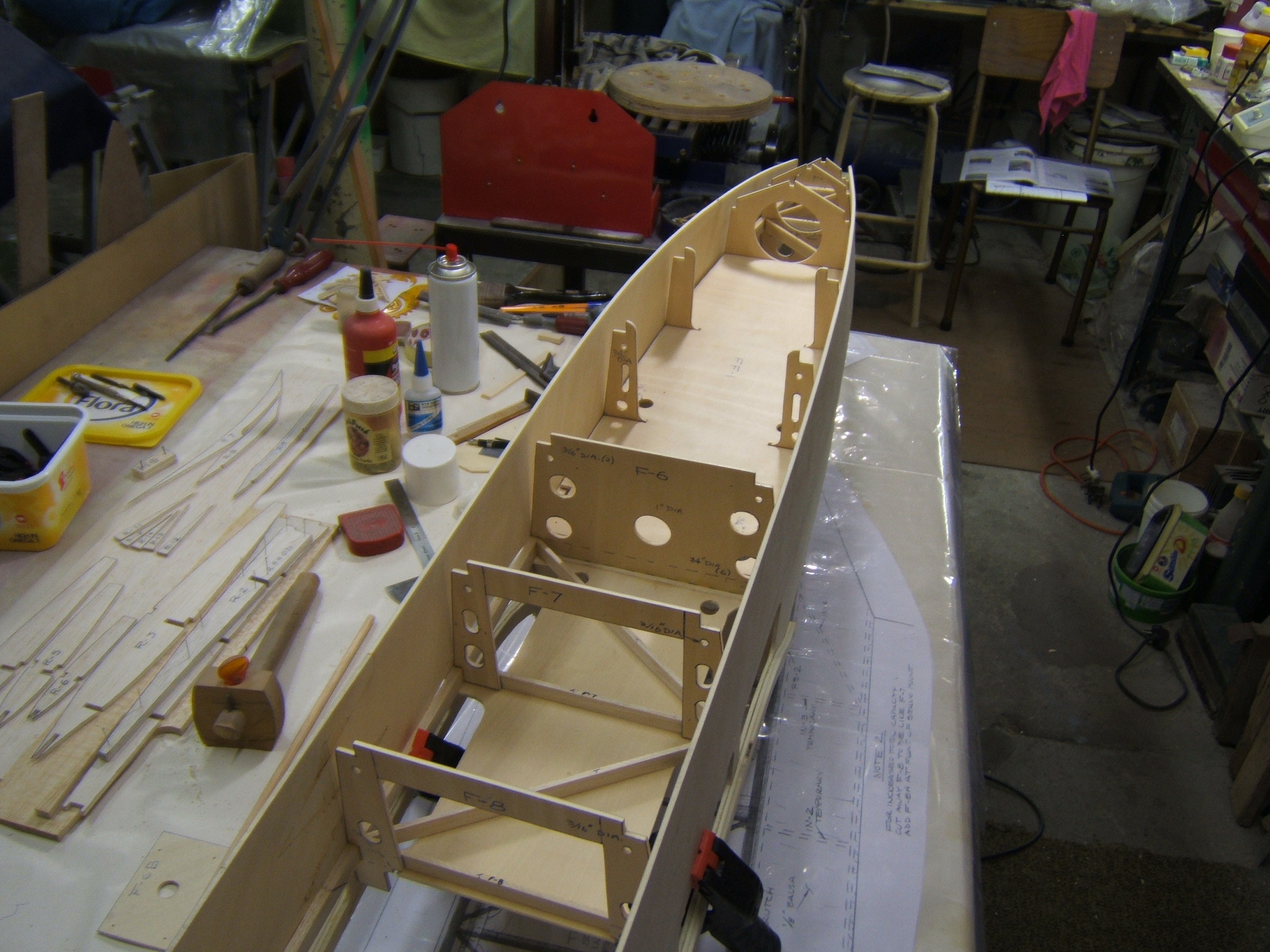
Just finished glueing the other fuselage side onto the crutch. The 1st stage is to glue the fuselage sides to the F6-F9 formers.
Regards
Craig

Just finished glueing the other fuselage side onto the crutch. The 1st stage is to glue the fuselage sides to the F6-F9 formers.
Regards
Craig
12-01-2013, 12:29 PM
#287

Hello everybody:
I sell special 3L tank for Turbinator.
http://www.rcmodelistas.es/foro/avio...-t4109-25.html
Regards from Spain.
Carlos Marquez
______________________________________
www.cmjets.blogspot.com
I sell special 3L tank for Turbinator.
http://www.rcmodelistas.es/foro/avio...-t4109-25.html
Regards from Spain.
Carlos Marquez
______________________________________
www.cmjets.blogspot.com
12-16-2013, 03:38 AM
#290
Senior Member
My Feedback: (1)
Join Date: Jan 2004
Location: Cape TownN/A, SOUTH AFRICA
Posts: 258
Likes: 0
Received 0 Likes
on
0 Posts
Hi Guys
I just added the lower 1/4" balsa stringers to the front section of the fuselage. I noticed in the photos of other turbinators,that the lower halves of the F3 and F4 fuselage formers had "doublers" glued to them? This is where the retract rails are situated. Nothing mentioned in the drawings or on the plan. So I made a doubler for each former and glued them in,before adding the stringers.
Regards
Craig
12-16-2013, 08:18 AM
#291
Senior Member
My Feedback: (1)
Join Date: Jan 2004
Location: Cape TownN/A, SOUTH AFRICA
Posts: 258
Likes: 0
Received 0 Likes
on
0 Posts
I made the nose wheel mounting rails from a piece of mahogany wood - all that I had on hand. Put it through a planer,to get the required size. Jigged them up inside the fuselage and glued them in position.
Regards
Craig

Regards
Craig
12-22-2013, 02:38 AM
#293
Senior Member
My Feedback: (1)
Join Date: Jan 2004
Location: Cape TownN/A, SOUTH AFRICA
Posts: 258
Likes: 0
Received 0 Likes
on
0 Posts
The nose wheel steering mount and the steering cable guide tubes have been installed. I just attatched the bottom front plywood floor and waiting for the glue to dry.
Regards
Craig


Regards
Craig
12-22-2013, 06:44 AM
#294
Senior Member
My Feedback: (1)
Join Date: Jan 2004
Location: Cape TownN/A, SOUTH AFRICA
Posts: 258
Likes: 0
Received 0 Likes
on
0 Posts
A word of advise here. Cut the front lover cover plate,a bit wider than what the drawing shows. Then once its glued,it can be trimmed down to match the fuselage contour. Almost done with the fitting of the screw tabs,which hold the cover in place.
Regards
Craig

Regards
Craig
 12-23-2013, 12:02 PM
#297
Senior Member
My Feedback: (1)
Join Date: Jan 2004
Location: Cape TownN/A, SOUTH AFRICA
Posts: 258
Likes: 0
Received 0 Likes
on
0 Posts
Hello Si_B
Thankyou for your remark. Its a lot of work and then the glue also takes time to dry. So its going a little slow now. I didn`t have any 1/2" X 3/4" hardwood,to use for the wing mounting rails,so I took 2 pieces of 6mm Lite Ply and epoxied them together,with a carbon fibre cloth in between them. I used epoxy resin to laminate the 2 pieces together and will cut it to the correct size.
I have a slight problem with the air ducting - they are numbered D1 and cut them out as there is 4 in total. I used carboard as a template,BUT can`t see how they must fit in there? Also the photo in the instructions is not clear as to where they are glued in and which way round?
Regards
Craig
12-24-2013, 06:13 AM
#298
Senior Member
My Feedback: (1)
Join Date: Jan 2004
Location: Cape TownN/A, SOUTH AFRICA
Posts: 258
Likes: 0
Received 0 Likes
on
0 Posts
Hi Guys
I cut the wing mounting rails from the laminated plywood sheet and glued them in position. Have a wonderful Christmas to all of you.
Regards
Craig

I cut the wing mounting rails from the laminated plywood sheet and glued them in position. Have a wonderful Christmas to all of you.
Regards
Craig
12-25-2013, 12:25 PM
#299

My Feedback: (31)
Join Date: Jan 2002
Location: Battle Creek,
MI
Posts: 175
Likes: 0
Received 0 Likes
on
0 Posts
Greetings and Merry Christmas from another Turbinator fan - also named Craig.
Your workmanship is very nice and I will continue to watch your thread closely,
even though I probably won't start building for another month or so. I like the looks
of the struts you bought from Dreamworks. What retracts will you be using with them?
Craig
Your workmanship is very nice and I will continue to watch your thread closely,
even though I probably won't start building for another month or so. I like the looks
of the struts you bought from Dreamworks. What retracts will you be using with them?
Craig
12-25-2013, 09:42 PM
#300
Senior Member
My Feedback: (1)
Join Date: Jan 2004
Location: Cape TownN/A, SOUTH AFRICA
Posts: 258
Likes: 0
Received 0 Likes
on
0 Posts
Hi Craig
Thankyou for your comment. I will be using the Airpower 85 Degree retract units for the main wheels and a 90 Degree retract unit from Model Mechanics,for the nose wheel. This Company doesn`t exist anymore,but their retracts were good quality.
Regards
Craig
Thankyou for your comment. I will be using the Airpower 85 Degree retract units for the main wheels and a 90 Degree retract unit from Model Mechanics,for the nose wheel. This Company doesn`t exist anymore,but their retracts were good quality.
Regards
Craig