


1/7th F-14D Scratch build thread *building started*


 05-15-2014, 01:01 PM
#1402
Since the pancakes are on Hold due to landing gear (story of my life... Or lack of!). I l have done some more work on the Tomcat.
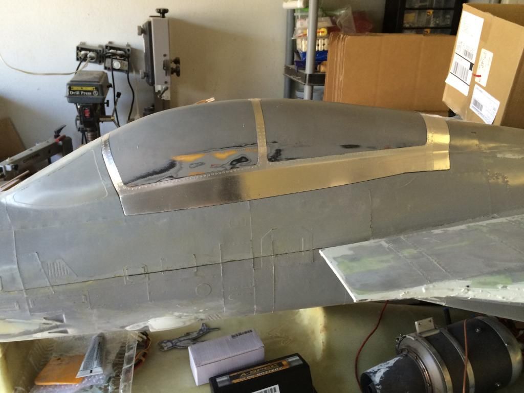
I was never happy with the canopy frame mold, so i pulled the plug back out, stripped off the litho plate, repaired it and redid all the detailin with flite metal.
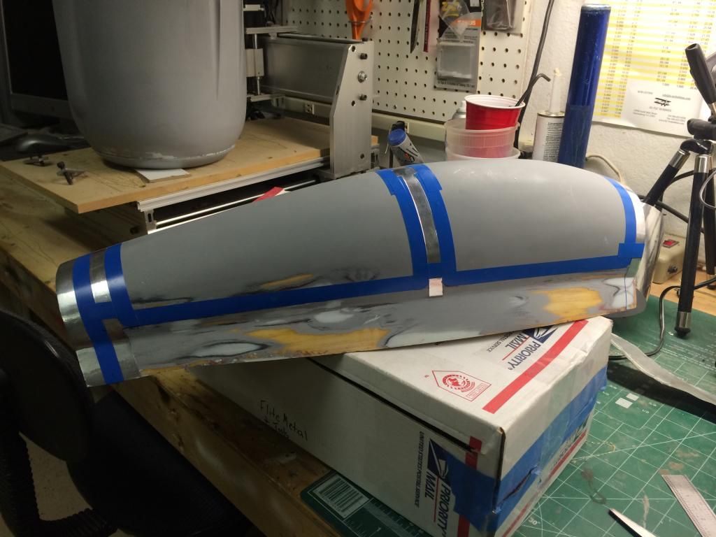
Then made up a new set of parting planes.
[URL=http://s.photobucket.com/user/Flamed04R6/media/F-14%20build%20stuff/2B3118E7-8E84-4E0D-B32E-4953A1F528D2_zpshchvnrax.jpg.html]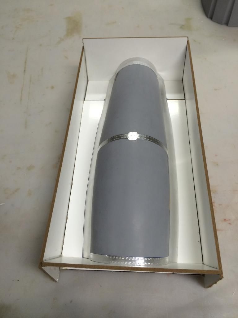 [/URL
[/URL
And remolded it. So far only the top half is done, ill do the bottom tomorrow. I also molded one half of a fuel tank as well.
I am still waiting on my special metal filled surface resin and epoxy dough, so i cant do the slat molds till i get that stuff... Once these molds are done I am really stuck as i wont have anything major to do for awhile. So it'll be back to body work on the parts already done i guess.
I was never happy with the canopy frame mold, so i pulled the plug back out, stripped off the litho plate, repaired it and redid all the detailin with flite metal.

Then made up a new set of parting planes.
[URL=http://s.photobucket.com/user/Flamed04R6/media/F-14%20build%20stuff/2B3118E7-8E84-4E0D-B32E-4953A1F528D2_zpshchvnrax.jpg.html]
[/URLAnd remolded it. So far only the top half is done, ill do the bottom tomorrow. I also molded one half of a fuel tank as well.

I am still waiting on my special metal filled surface resin and epoxy dough, so i cant do the slat molds till i get that stuff... Once these molds are done I am really stuck as i wont have anything major to do for awhile. So it'll be back to body work on the parts already done i guess.
05-16-2014, 11:28 AM
#1404
Thanks Ivan!
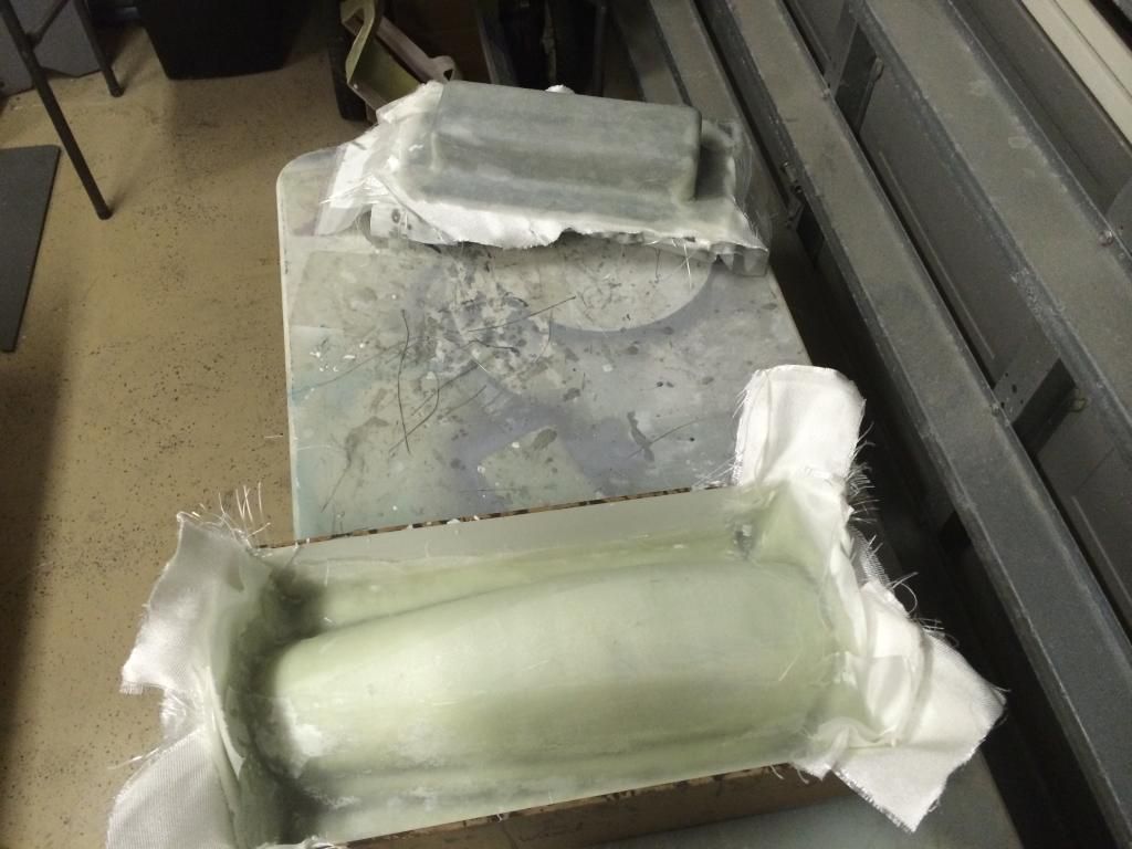
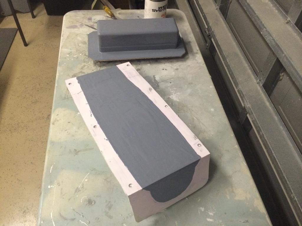
Canopy frame parting planes removed:
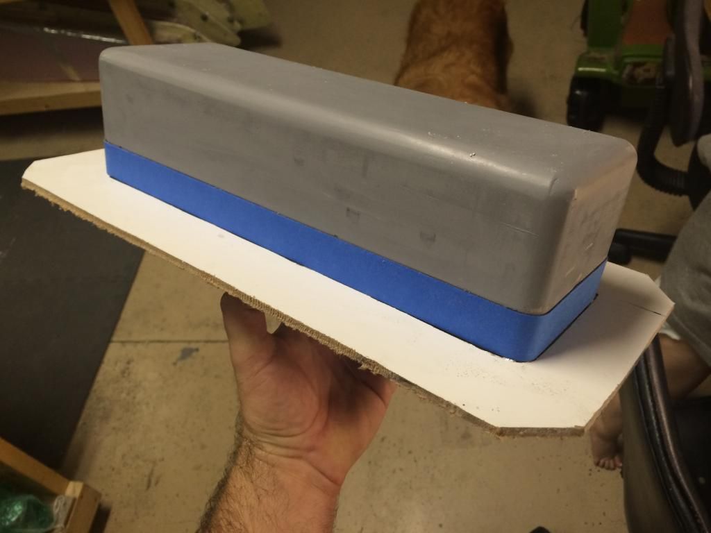
First half of a fuel tank mold:
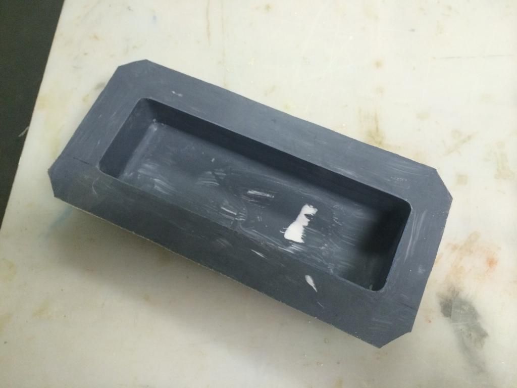
Now for the second half i am making a overlapping lip. Basically just take 1/2" masking tape and keep going around the tank to build up some thickness. Then put the parting plane back in position.
Then the surface resin is applied to the second half of each mold. For the canopy frame i am doing a two stage process. I used the white surface resin and mixed in some West graphite powder to give it a grey color. I think brushed it onto just the plug being very carefull not to get it on the parting plane surface. This will give me a noticeable edge to trim to when getting ready to join the two halves of the mold. Ill come back later and coat the entire thing with the white resin in an hour or so.
Canopy frame parting planes removed:

First half of a fuel tank mold:

Now for the second half i am making a overlapping lip. Basically just take 1/2" masking tape and keep going around the tank to build up some thickness. Then put the parting plane back in position.

Then the surface resin is applied to the second half of each mold. For the canopy frame i am doing a two stage process. I used the white surface resin and mixed in some West graphite powder to give it a grey color. I think brushed it onto just the plug being very carefull not to get it on the parting plane surface. This will give me a noticeable edge to trim to when getting ready to join the two halves of the mold. Ill come back later and coat the entire thing with the white resin in an hour or so.
 05-16-2014, 11:37 AM
#1405

Thomas, thanks for positing.
Regarding that fuel tank lip, how do you make the extension on the other half of the mold (the part of the tank half that will end up going into that raised lip on the other half)?
I assume the original plug was basically the final size you needed, just an assumption on my part.
Regarding that fuel tank lip, how do you make the extension on the other half of the mold (the part of the tank half that will end up going into that raised lip on the other half)?
I assume the original plug was basically the final size you needed, just an assumption on my part.
05-16-2014, 11:44 AM
#1406
Matt,
you will notice that the first half of the tank mold isnt on the plug. Before removing the mold, a line is drawn at the parting plane location onto the plug around its perimeter. Then the mold half is removed. This line is used to put the tape into position. The tape is placed on the same side of the line as the first mold half. The parting plane is then moved to the edge of the tape furthest from the line you drew. This makes the next mold half larger by the width of the tape. You now essentially have a pair of molds that will make a tank 1/2" larger than the plug IF you were to butt seam them. But because of the overlap lip, one side will slip over the other half giving you a tank the same size as the original. Then all you have to do is build up the tanks like you would a pair or BVM tanks.
I could have made these tanks shorter and taller to conform to the inside of the fuselage, but i disnt. Reason being is i wanted to be able to put a custom smoke tank or "extra fuel " tank ontop of these tanks so as to keep all the tanks in one location and to keep the amount of tanks to a minimum. Because of that i will have to put a baffle half way down the length as these tanka are 12" long.
Fuel Qty. Wise, there is just over 1 gallon of fuel per engine.
05-16-2014, 12:35 PM
#1407
Hi Thomas,
OK I get it, you slide the plug up, good trick. That does mean the plug sides have to be uniform (parallel) at least in that region, for the length of the "slide"? I have a tank to do, hence the question. I don't think my plug has an region like this, but it is a neat idea. I have seen this lip think done before, but the person had to build another mold that went over one side and built up the lip. Hassle.
OK I get it, you slide the plug up, good trick. That does mean the plug sides have to be uniform (parallel) at least in that region, for the length of the "slide"? I have a tank to do, hence the question. I don't think my plug has an region like this, but it is a neat idea. I have seen this lip think done before, but the person had to build another mold that went over one side and built up the lip. Hassle.


 05-17-2014, 11:28 AM
#1413
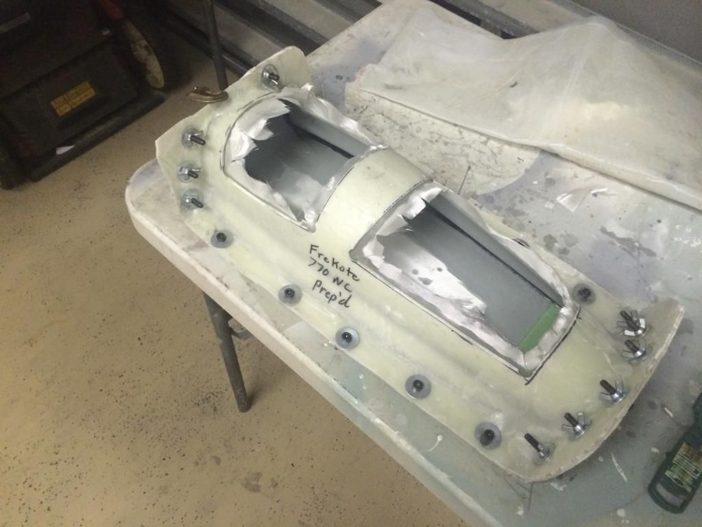
The plugs are all removed from the molds. They were then washed with soap and water to remove the amine bloom and mold release. I then stuck them out in the driveway for an hour to dry and post cure somewhat. Then they were brought in to cool and cleaned two more times with Frekote PMC. After a 30 minute dry time i can begin applying the mold sealer and release.
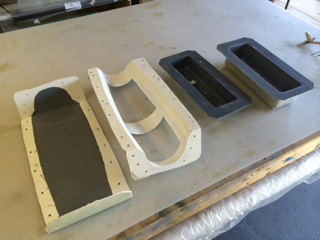
The canopy frame plug came out perfect with no sticking of the flitemetal.
A helpfull hint for those who may try the overlapping flange trick. If you ise regular masking tape, be sure to either A. Wax it REALLY good (6-10coats) or B. Seal it with some aluminum Duct tape. I didnt wax it enough and the masking tale caused allot of headache in getting the plug out. After an hour i just said screw it and tore the plug out. I have two tank plugs anyways.

The canopy frame plug came out perfect with no sticking of the flitemetal.

A helpfull hint for those who may try the overlapping flange trick. If you ise regular masking tape, be sure to either A. Wax it REALLY good (6-10coats) or B. Seal it with some aluminum Duct tape. I didnt wax it enough and the masking tale caused allot of headache in getting the plug out. After an hour i just said screw it and tore the plug out. I have two tank plugs anyways.
 05-18-2014, 12:28 PM
#1415
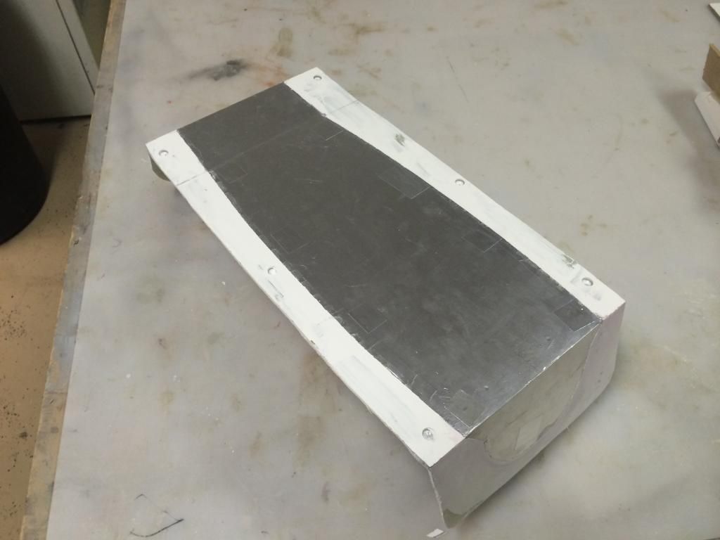
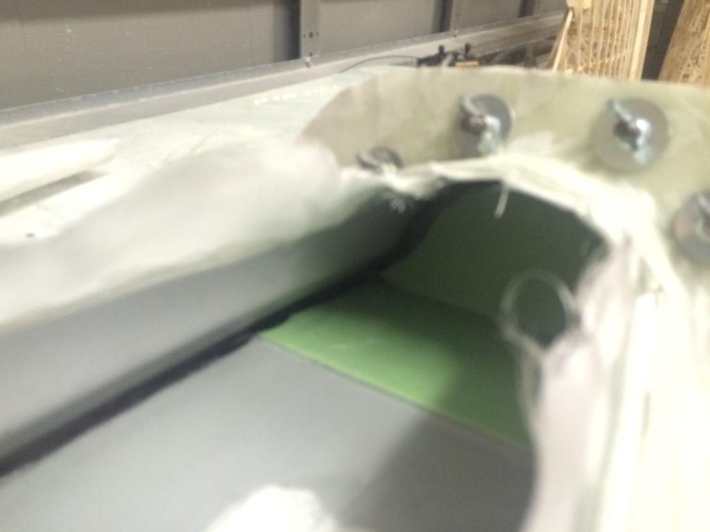
The canopy frame halves are layed up, then left to to green for an hour. Them the overhang is trimmed on the actual frame mold. The base mold the glass layers are carefully cut to the proper size and placed on the mold aligning the edge or the fiberglass with the grey edge on the mold. The halves were then bolted together while still green. This is something new i am trying as with the last mold it was very difficult to get the two portions of the mold together perfectly if the glass was oversize at all (it didnt help how that mold was messed up either). By clamping the molds together while the glass is still green, i am hoping the flanges will help compress the layup enough to get a perfect seam.
The inside corners where the two layups meet then had two strands of 50k carbon tow stuffed tightly into them. These are going to provide some bending resistance and join the two layups together.

The inside corners where the two layups meet then had two strands of 50k carbon tow stuffed tightly into them. These are going to provide some bending resistance and join the two layups together.


 05-19-2014, 09:18 AM
#1417

My Feedback: (12)

Join Date: Aug 2002
Location: Scottsdale, AZ
Posts: 4,462
Likes: 0
Received 0 Likes
on
0 Posts
The plugs are all removed from the molds. They were then washed with soap and water to remove the amine bloom and mold release. I then stuck them out in the driveway for an hour to dry and post cure somewhat. Then they were brought in to cool and cleaned two more times with Frekote PMC. After a 30 minute dry time i can begin applying the mold sealer and release.
The canopy frame plug came out perfect with no sticking of the flitemetal.
A helpfull hint for those who may try the overlapping flange trick. If you ise regular masking tape, be sure to either A. Wax it REALLY good (6-10coats) or B. Seal it with some aluminum Duct tape. I didnt wax it enough and the masking tale caused allot of headache in getting the plug out. After an hour i just said screw it and tore the plug out. I have two tank plugs anyways.
Thomas, next time try either Styrene or ABS sheet. Cut a strip the width you need for the flange of what ever thickness you want the flange to be and glue or double stick tape it on. Hardly any waxing needed for that.
05-30-2014, 04:22 PM
#1419
Now that its a month after the initial order and 2 weeks since being charged and the second order for the same materials, i finally got fed up with waiting any longer and got started on doing the leading edge slat molds.
So the top half is done:
So the top half is done:

 06-01-2014, 01:54 PM
#1421
I popped the mold apart, pulled the plugs out, cleaned it all up and prepped it for layup. Im not happy with how the back side mold turned out and actually have a revelation on how I should of done it to eliminate the problems i have with it. So for the time being, im going to abandon the back mold segment until the epoxy dough arrives.
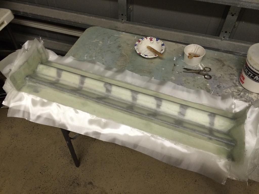
So i laid up the leading edge slats. 2 layers of glass, 1 layer of carbon, some 1.2mm airex core, some more carbon in the slider and servo mount locations and then a final layer of glass. The entire thing is thrown in the vacuum bagged with The Industrial Suck on it. This time i reduced the vacuum from 26" like i had been using to 20" to try and eliminate some resin lean issues i have had on a few parts in areas.
I also took a panelling nail and perforated the airex core. I have noticed air bubbles trapped between the glass and the airex core on one part that i am attributing to the prewetting of the airex core before placing in the layup and the air bubble being unable to escape. The perforations should fix that.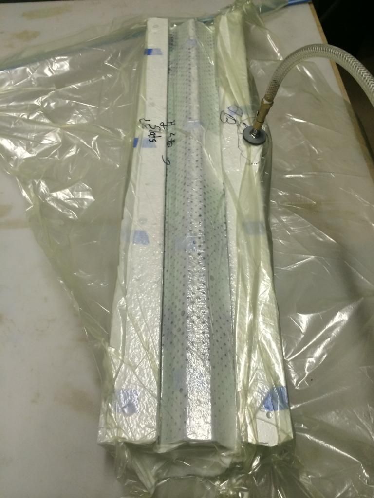
 06-02-2014, 02:04 PM
#1422
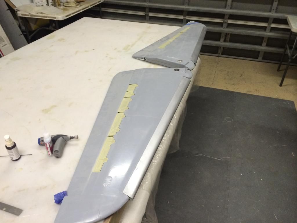
And here we have the slats fresh from the molds. I painted these silver since the vast majority of the slat is unpainted on the real thing.

Then the slider rail holes and pushrod linkages were cut in the wings and the entire assembly mocked up with the sliders in place.


Then i adjusted the slat sliders where they glue to the slat so the slat closes tight and flush with the wing leading edge. It was all tack glued together and verified it all slid together nicely. Im happy to say that the slider ribs are perfectly aligned and the slat moves Very easily!
Then i made up the pushrod linkage rib for the slat. Unfortunately i didnt get many pictures of this as it was lots of adjusting and test fitting to get it all to fit perfect when up and down.
Here it is with the torque tube linkages and all hooked up.


The deflection forward and down is not alot, but it should be sufficient, the next set of wings i do, i will make a slight change to the torque tube position and place a lightning hole in the sheer web so the torque tube arms can move a bit more. I believe with these two changes i should be able to get another 1/2-1" of movement from the slat.
Overall, all of the fears i had were for nothing as this system is extremely easy for a servo to manipulate the slat, even when pressure is placed on the slat by hand. Later tonight ill do the other wing and go hysol all the slat and spoiler hinge parts. Tomorrow ill prime the spoilers and put it all back together and start installing servos, flap linkages, etc since wing construction is essentially Done!
06-02-2014, 06:18 PM
#1423
I went back out after dinner and did wing #2.
And here is the backside of the slats removed from the wing:
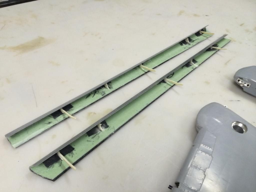
Ive got a few changes ill make to the slat layup, but it is essentially perfect. All of the slat, spoiler torque tube parts and flap hinges are all hysol'd in place. Tomorrow i have to fix the Shop A/C, then ill so some body work to everything. I would do the final install of the spoilers and all, but i forgot i have to order about 100 button socket screws and miniature lock nuts. Oh well, plenty of Other stuff to do.
06-04-2014, 04:57 PM
#1425


Great work again Thomas..
I�m a bit confused on the slat activation you have designed. Are they activated with a single toque tube running the length of the wing??
Your F-14 Slats look very similar in design to the BVM Hun slats. (Which I consider a compliment BTW). The BVM slats utilize two wing mounted servos.
And please keep posting here.. This thread is RCU GOLD.
Roger