PBY Catalina (Vintage Plans) Build Thread

 02-06-2020, 06:21 PM
#78
Senior Member
I'm open to other ideas and suggestions as this is my first water borne aircraft.
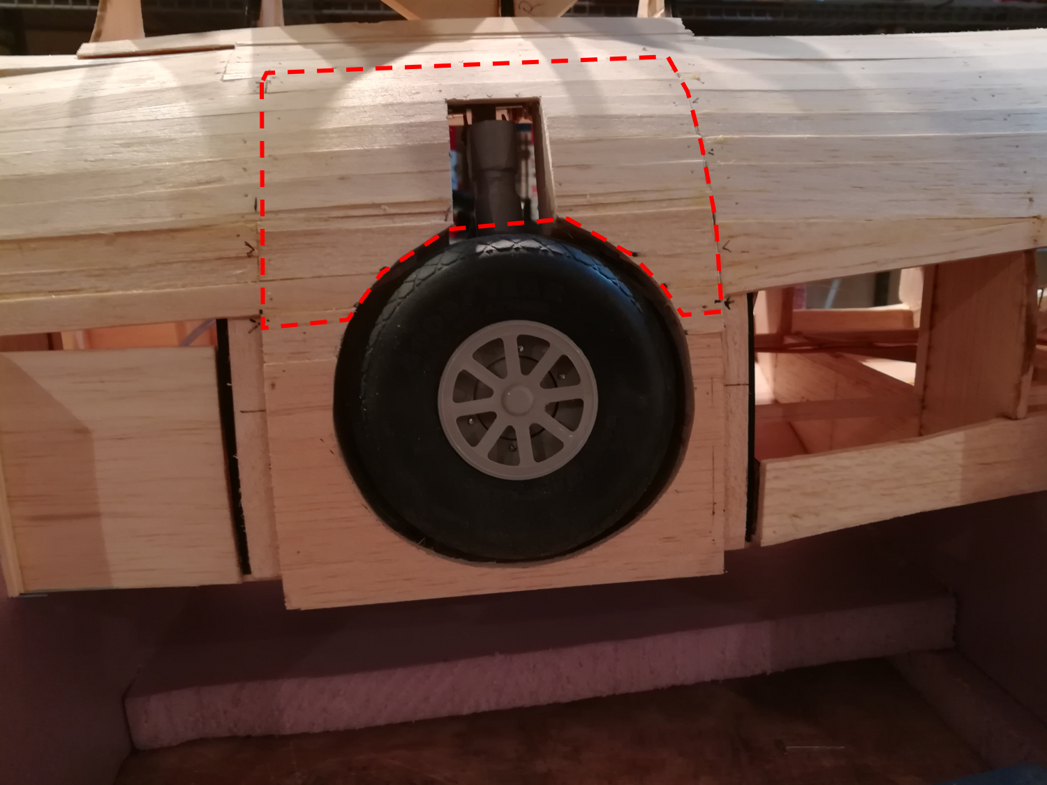
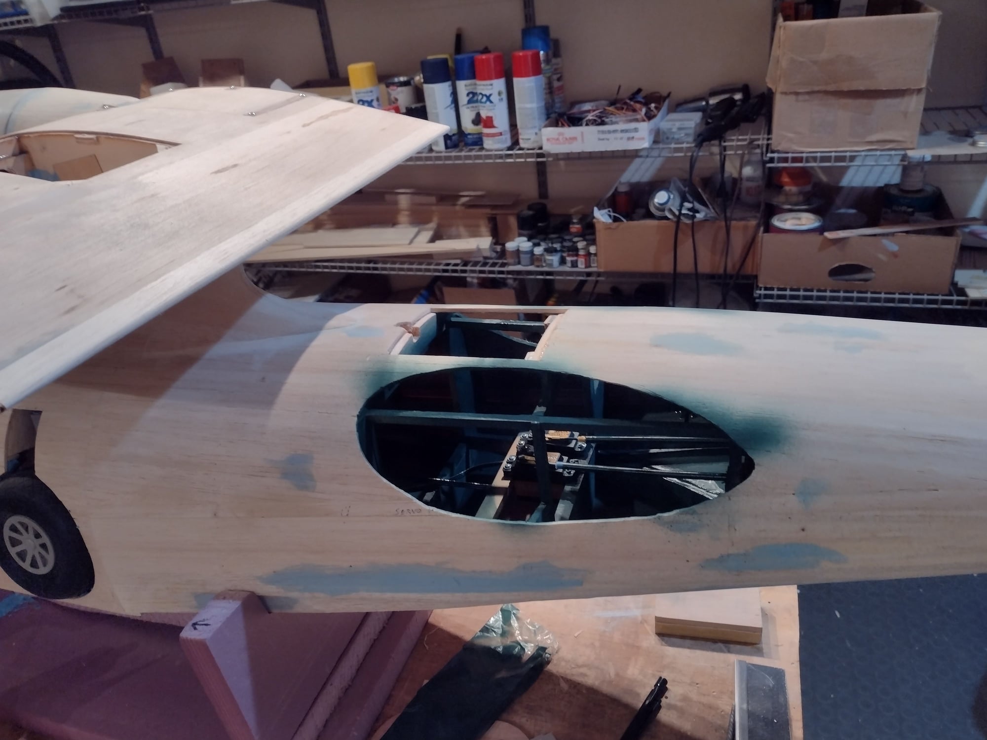
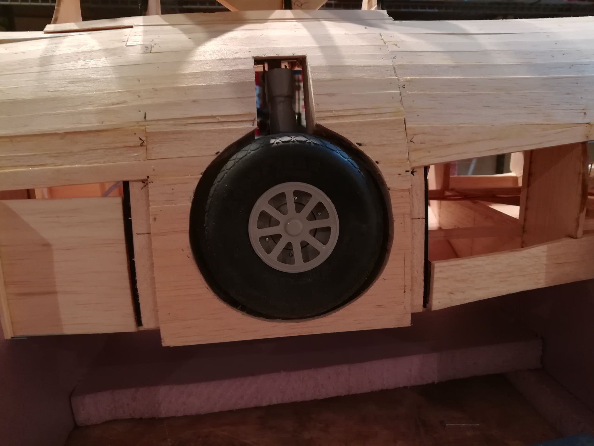
outline of gear access hatch.
02-06-2020, 06:25 PM
#79
Senior Member
The planking of the fuse in complete now. Here's some picts of the final stages. LOTS of sanding and filling to do!!
In the first pict, you can see the structure below the planking that will allow me to cut the hatch free and have it retain its shape.
the structure to support the gear access hatch.
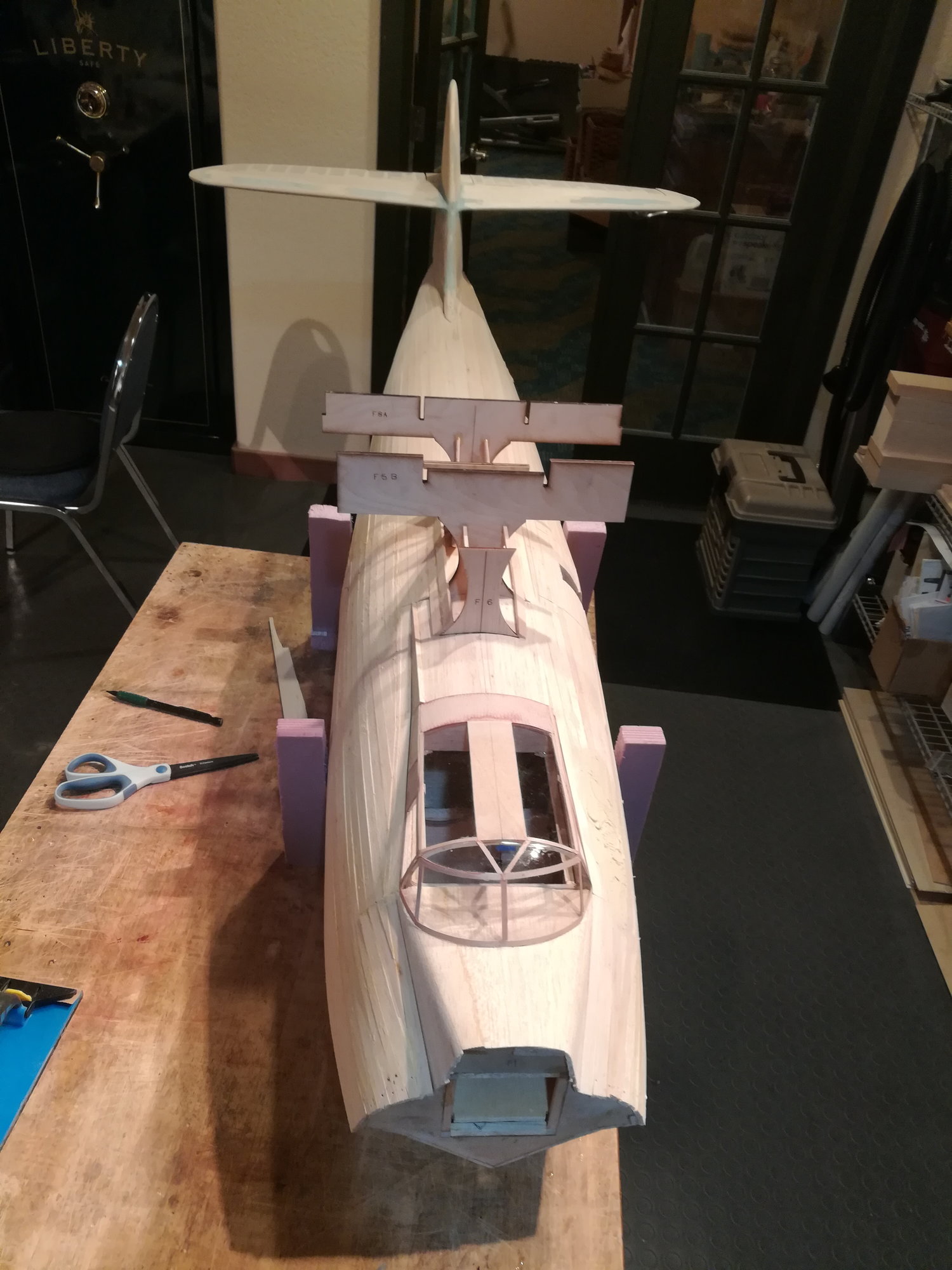
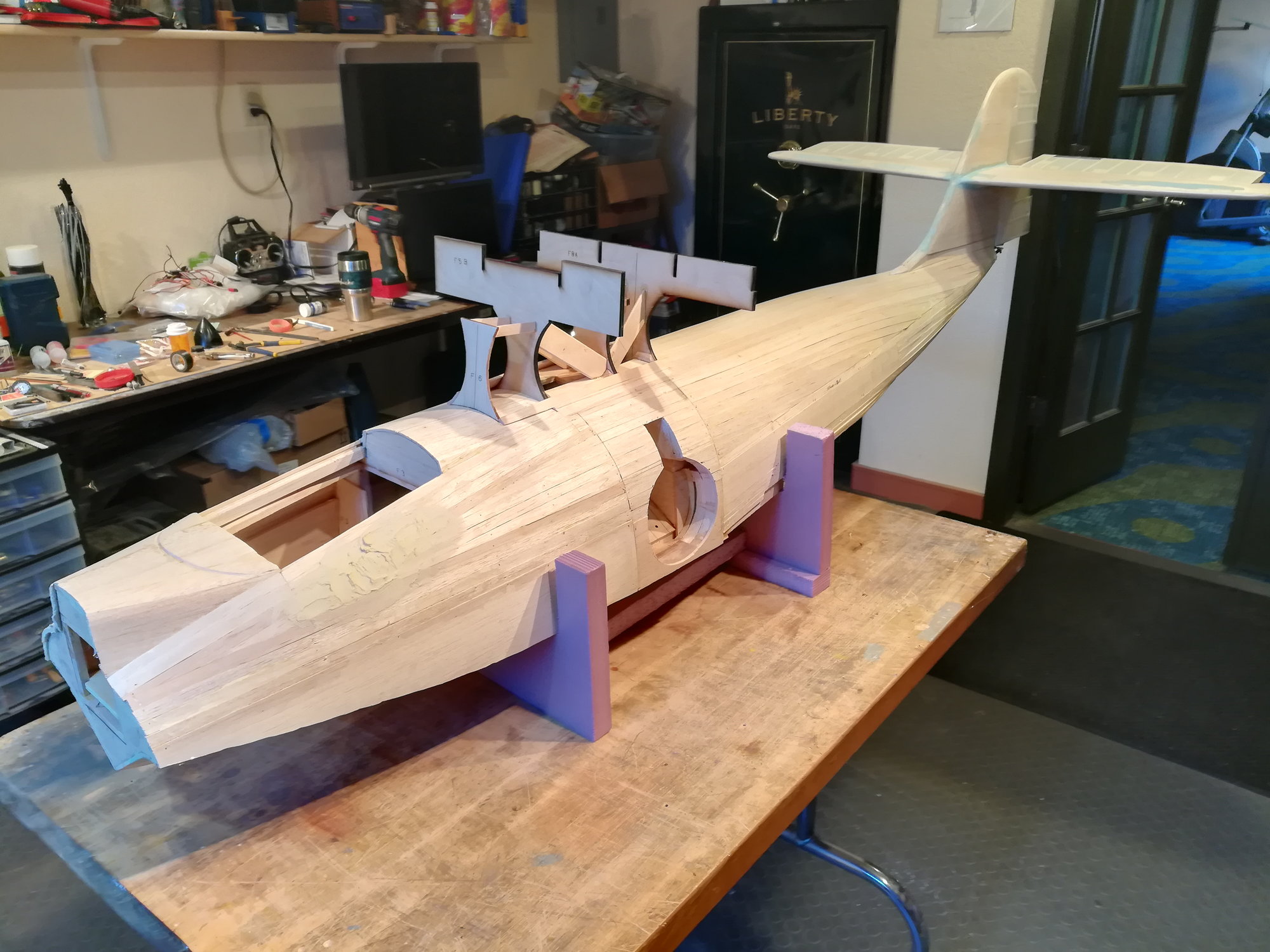
In the first pict, you can see the structure below the planking that will allow me to cut the hatch free and have it retain its shape.
the structure to support the gear access hatch.
02-06-2020, 06:35 PM
#80
Senior Member
OK, been working on the nose "block". I use 1/8" ply cut to the profile of the nose. This goes down the centerline of the fuse. Blocks are added to each side. The bombardier's window is also ply. This helps me sand to just the right shape and helps strengthen the nose against dings.
This is the work in progress, it's not right just yet but getting close.
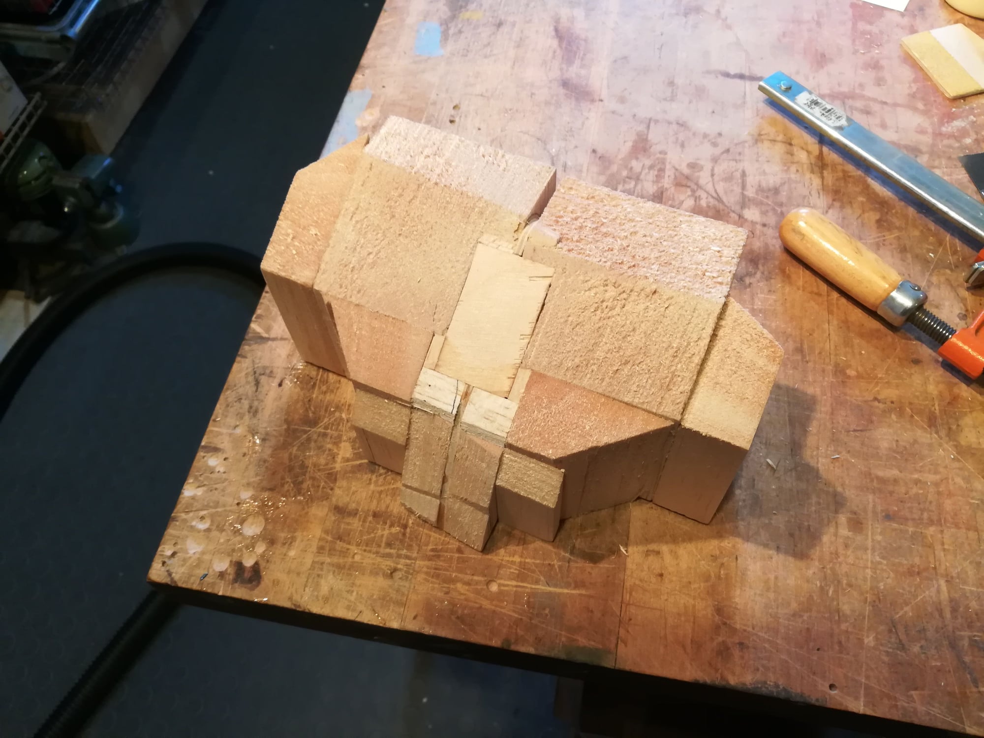
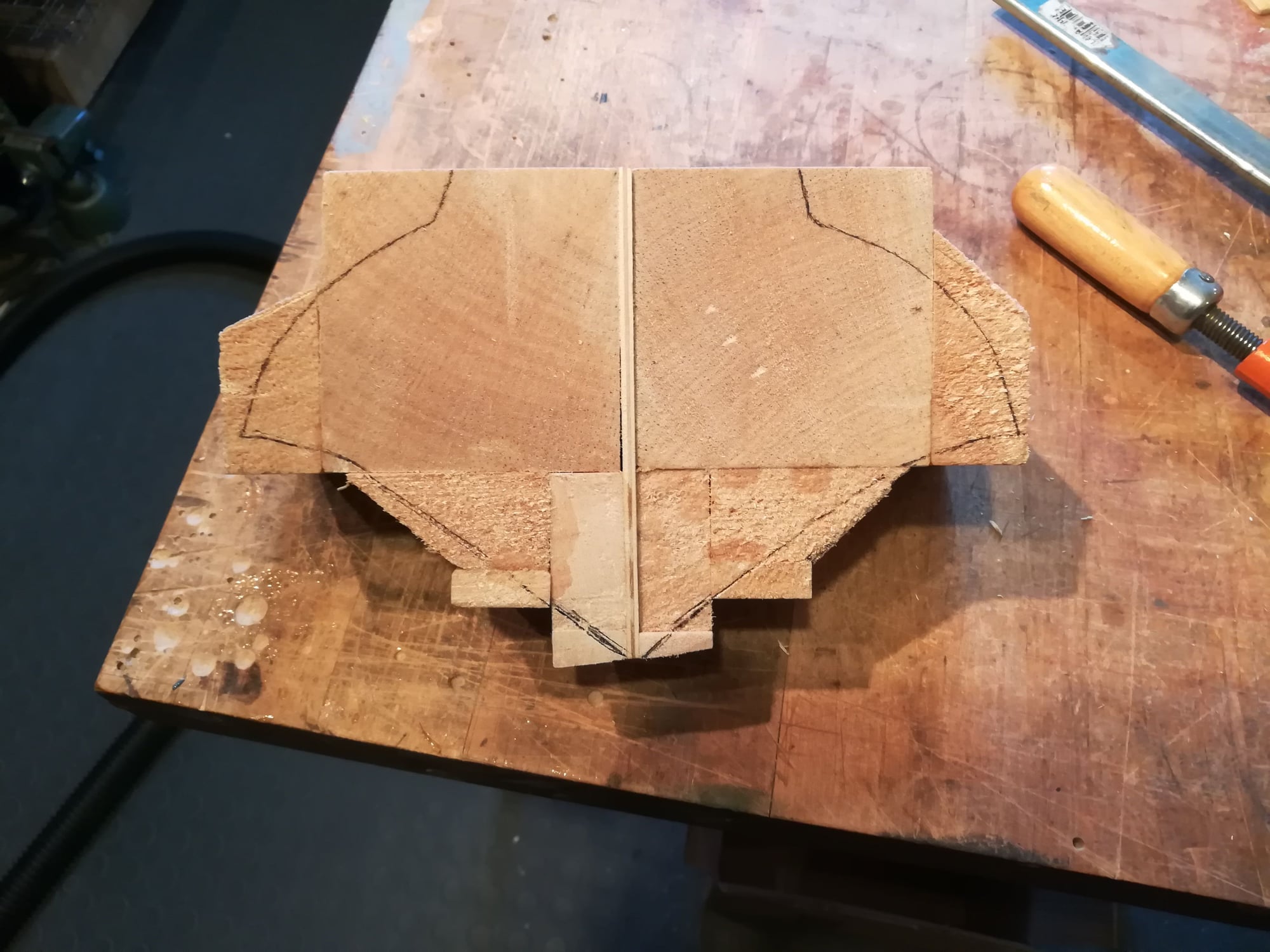
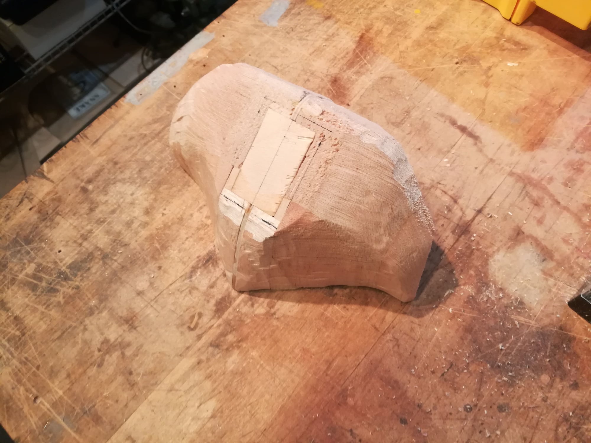
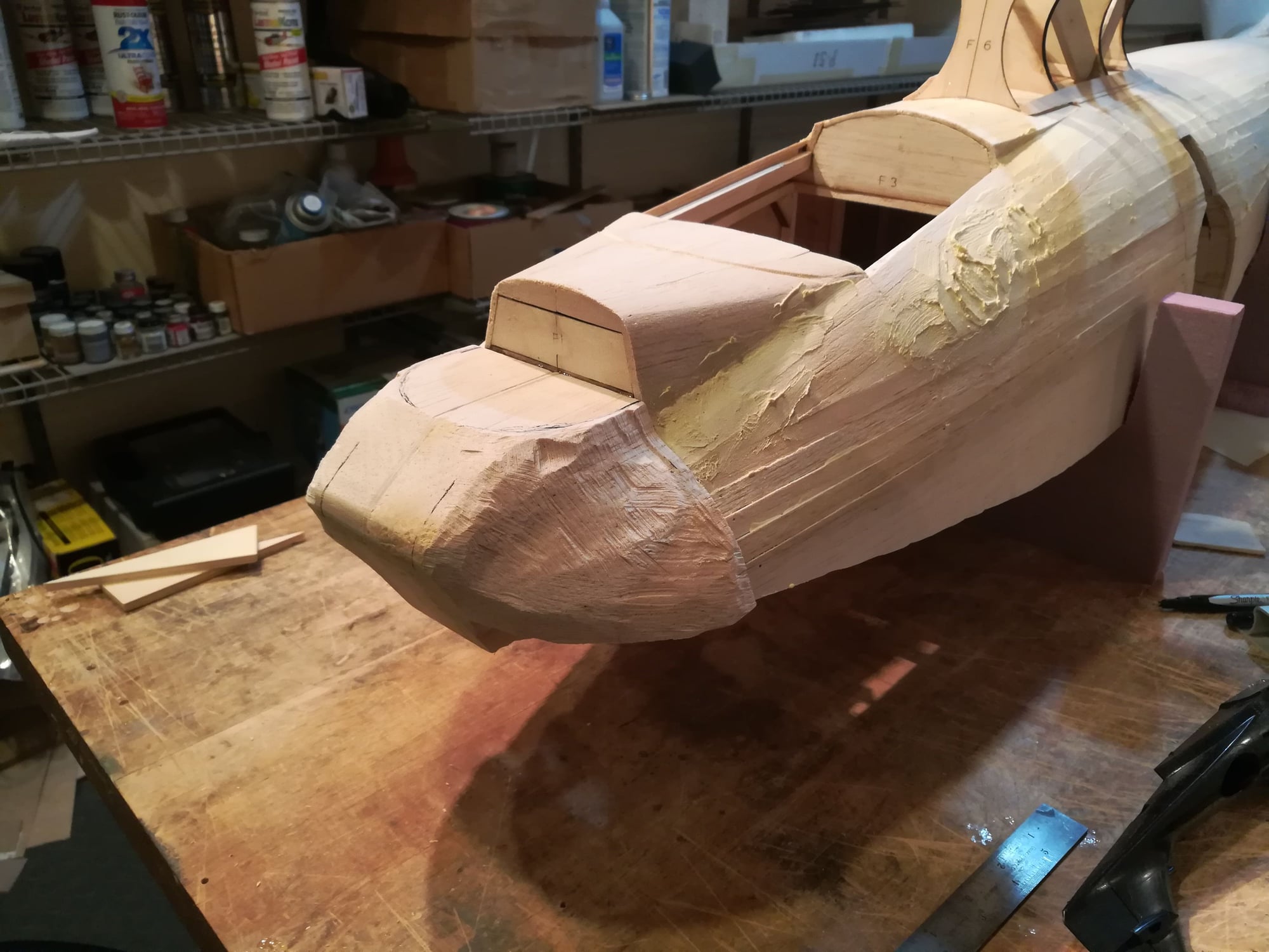
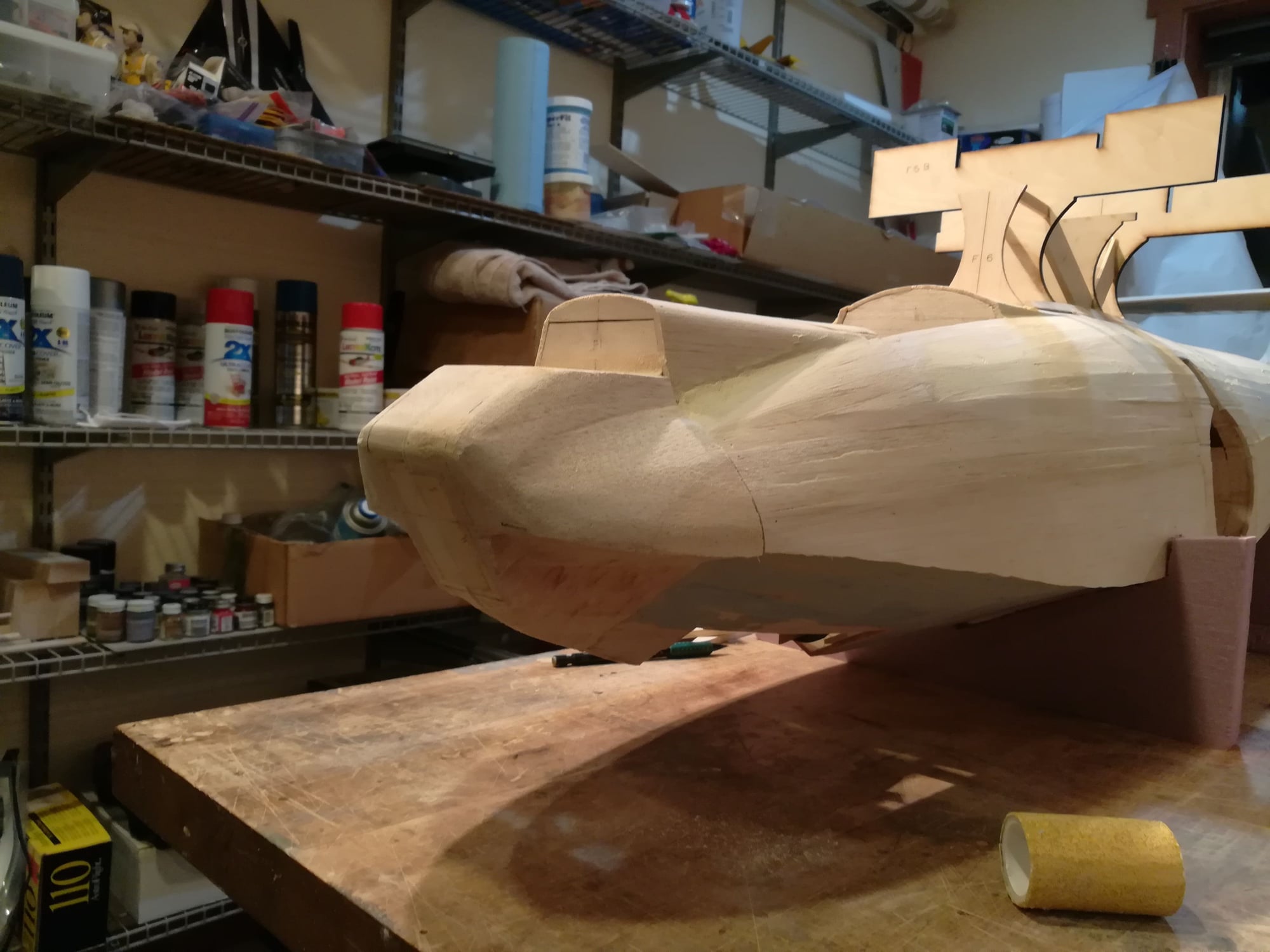
This is the work in progress, it's not right just yet but getting close.
02-07-2020, 06:53 AM
#81

My Feedback: (101)
Nice work. You make it look easy. I imagine hatches, water proofing and stressing the fuse are major concerns. I have to rethink adding retracts to mine after looking at the structural changes you are making. I am considering just making the mains and the nose gear removeable so that I can still fly it at the local airfield. keep up the good work.
02-09-2020, 08:20 AM
#82
Senior Member
I'm glad I "make it look easy"  ... to put a number on it, getting the nose block complete from start to finish has been about 12 hours of work .
The retracts do require a lot of structural support. I am also concerned about the hull. The Vintage plane was designed to have fixed gear (i.e. not designed for water). So I will be applying 2 layers of very thin carbon fiber to the sheeting on the hull.
... to put a number on it, getting the nose block complete from start to finish has been about 12 hours of work .The retracts do require a lot of structural support. I am also concerned about the hull. The Vintage plane was designed to have fixed gear (i.e. not designed for water). So I will be applying 2 layers of very thin carbon fiber to the sheeting on the hull.
02-09-2020, 08:42 AM
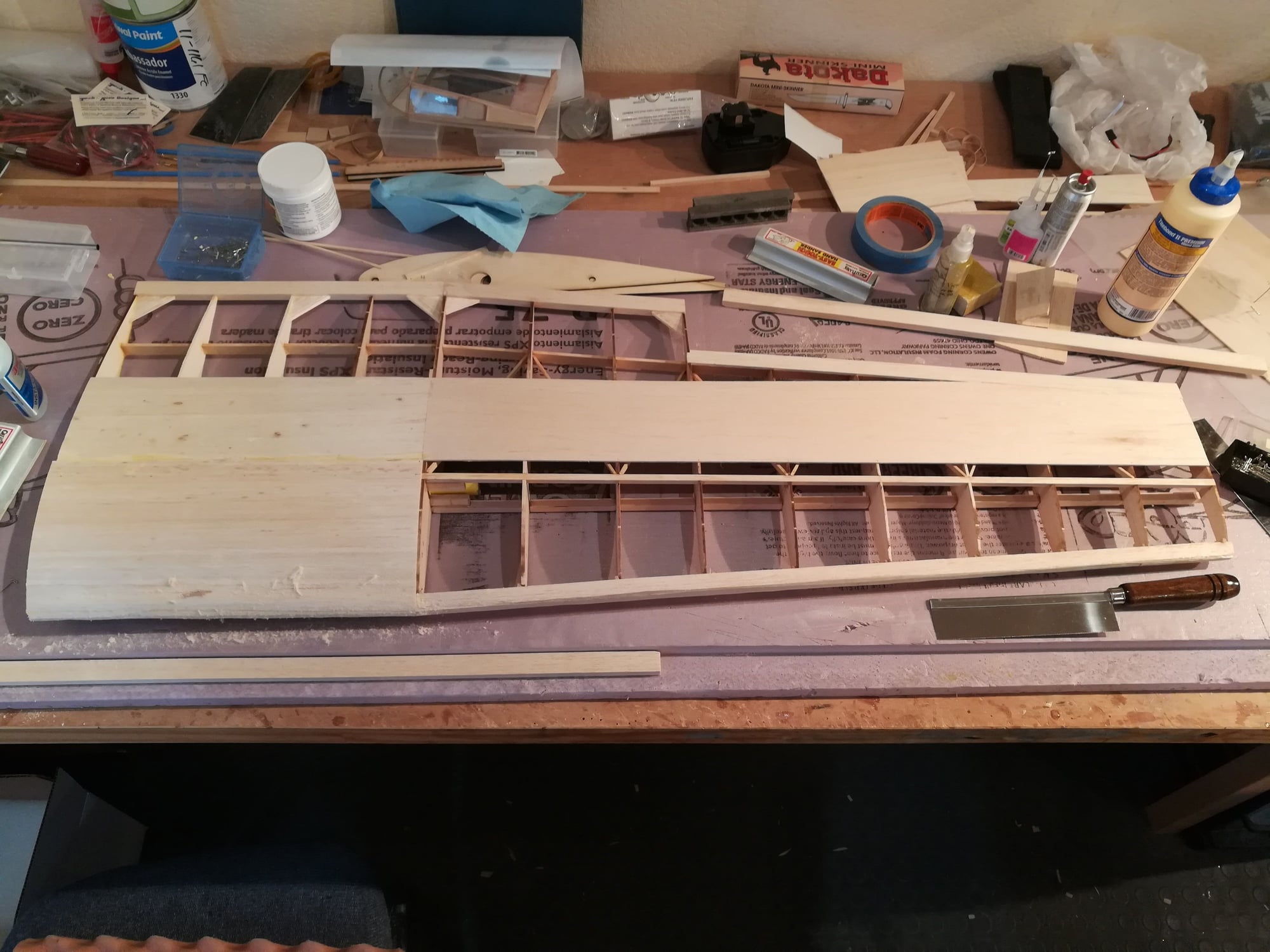
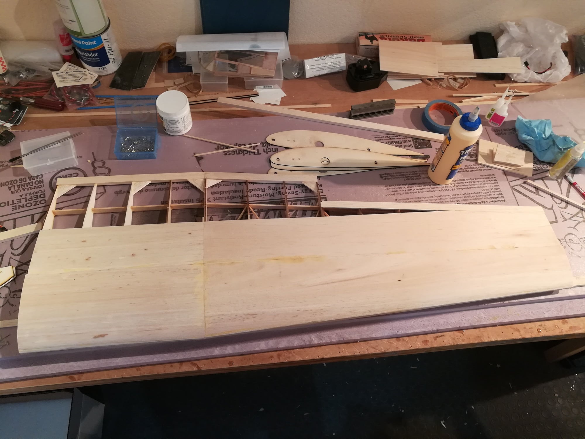
#83
Senior Member
On to the wing!
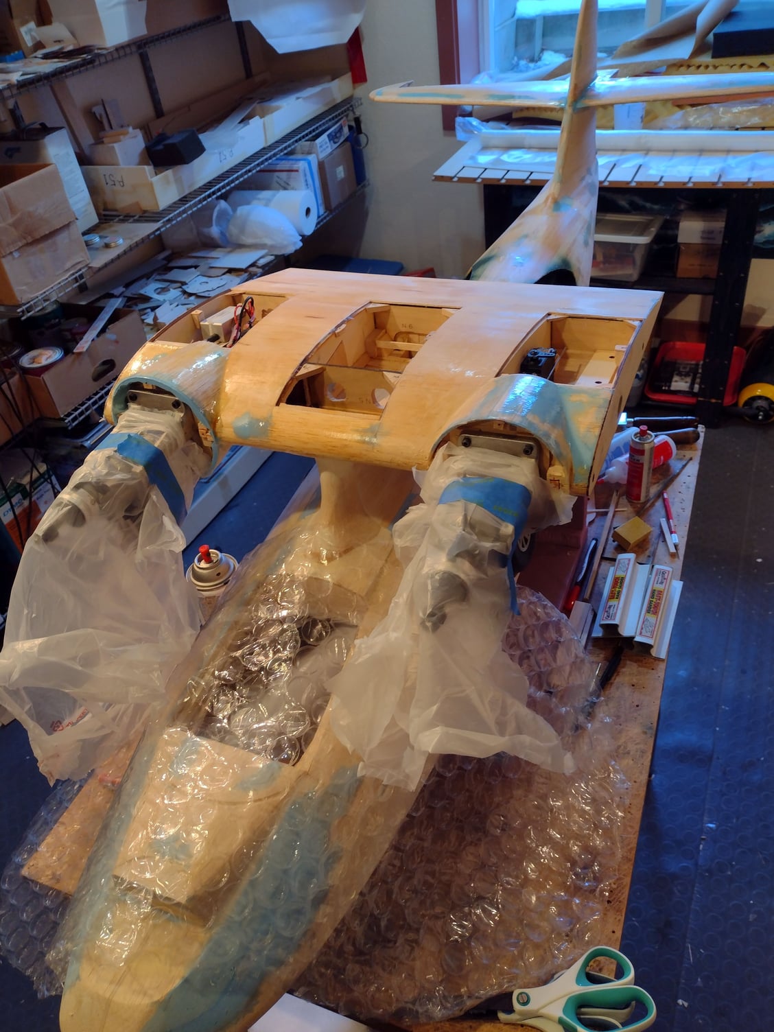
What looks on the surface to be a fairly simple wing is actually more complex than I had expected. A large center area is constant chord. Two outer panels are tapered. The top of the wing is flat tip to tip (no dihedral), but the bottom of the tapered sections do taper up to the tip. A narrow center section is fixed to the pylon with 2 removable sections (typical). But the removable sections contain both constant chord and tapered sub-sections. And the wing uses a slightly semi-symmetrical airfoil. The center section embeds the 2 nacelles. Typically, the nacelles are built separately (like on my A-26) because they are quite large holding the main landing gear. Here the nacelles are small and they are designed integrally with the wing spar. I've decided to build the wing in 5 sections. The 2 outer sections of each side will be joined once built. The center section will be built "in the air" right on the pylon. This is only possible because a key section of the spar is already part of the pylon and the designer created interlocking parts. Even still, a lot of dry fitting and aligning while clamping was required. Here's some picts of the right outer panel and the center section on the fuse.
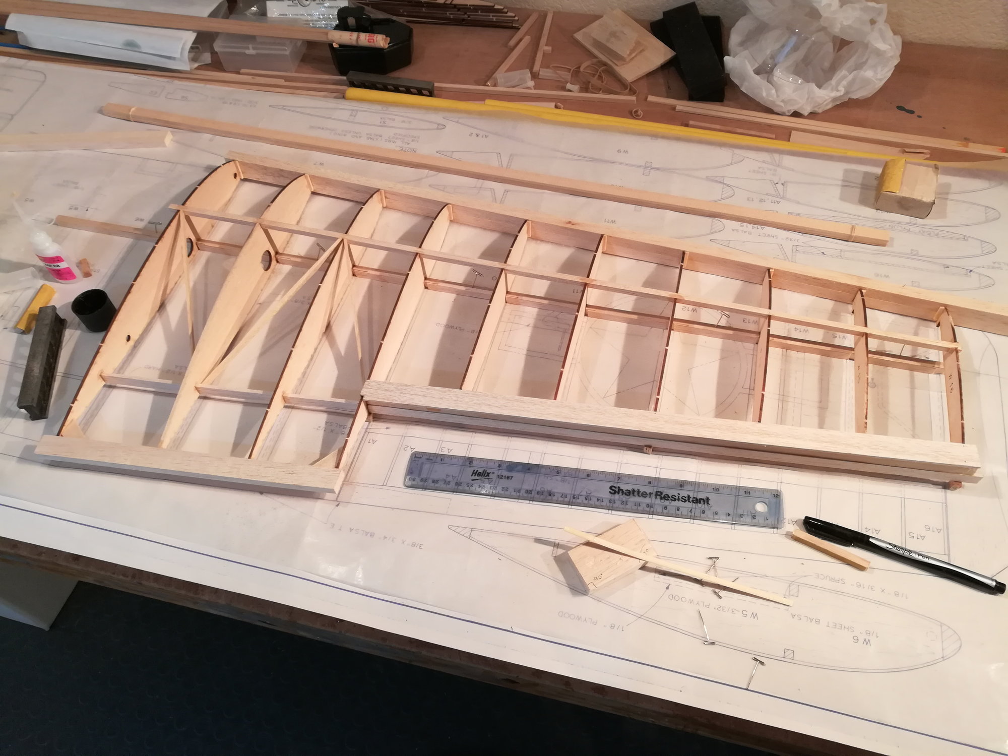
What looks on the surface to be a fairly simple wing is actually more complex than I had expected. A large center area is constant chord. Two outer panels are tapered. The top of the wing is flat tip to tip (no dihedral), but the bottom of the tapered sections do taper up to the tip. A narrow center section is fixed to the pylon with 2 removable sections (typical). But the removable sections contain both constant chord and tapered sub-sections. And the wing uses a slightly semi-symmetrical airfoil. The center section embeds the 2 nacelles. Typically, the nacelles are built separately (like on my A-26) because they are quite large holding the main landing gear. Here the nacelles are small and they are designed integrally with the wing spar. I've decided to build the wing in 5 sections. The 2 outer sections of each side will be joined once built. The center section will be built "in the air" right on the pylon. This is only possible because a key section of the spar is already part of the pylon and the designer created interlocking parts. Even still, a lot of dry fitting and aligning while clamping was required. Here's some picts of the right outer panel and the center section on the fuse.
 03-01-2020, 03:57 PM
#87
Senior Member
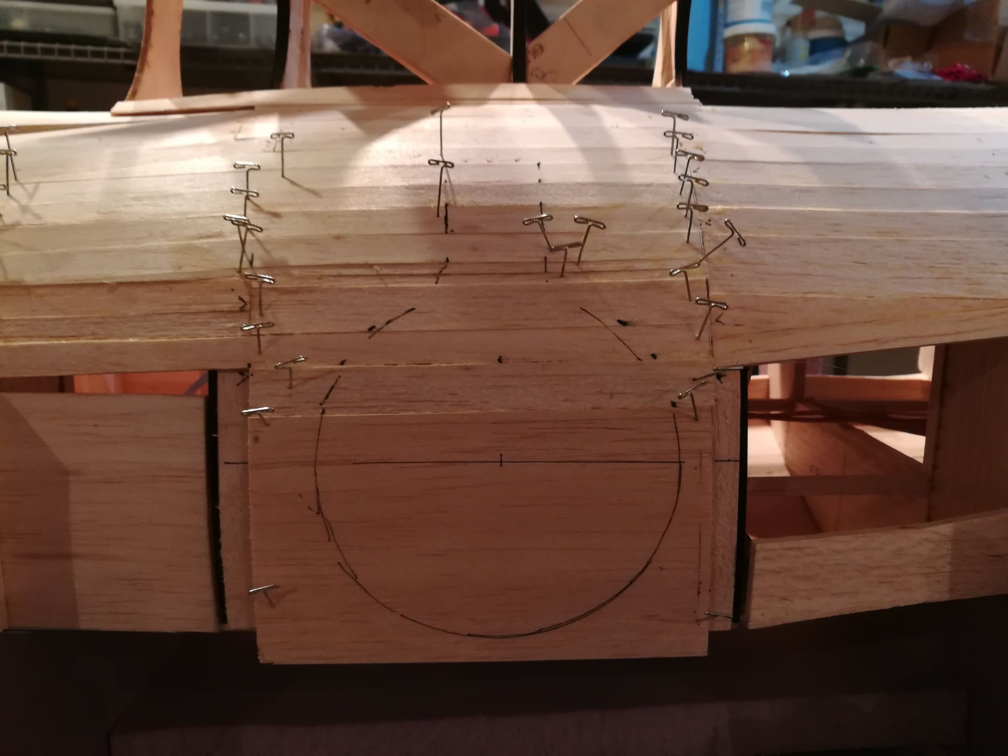
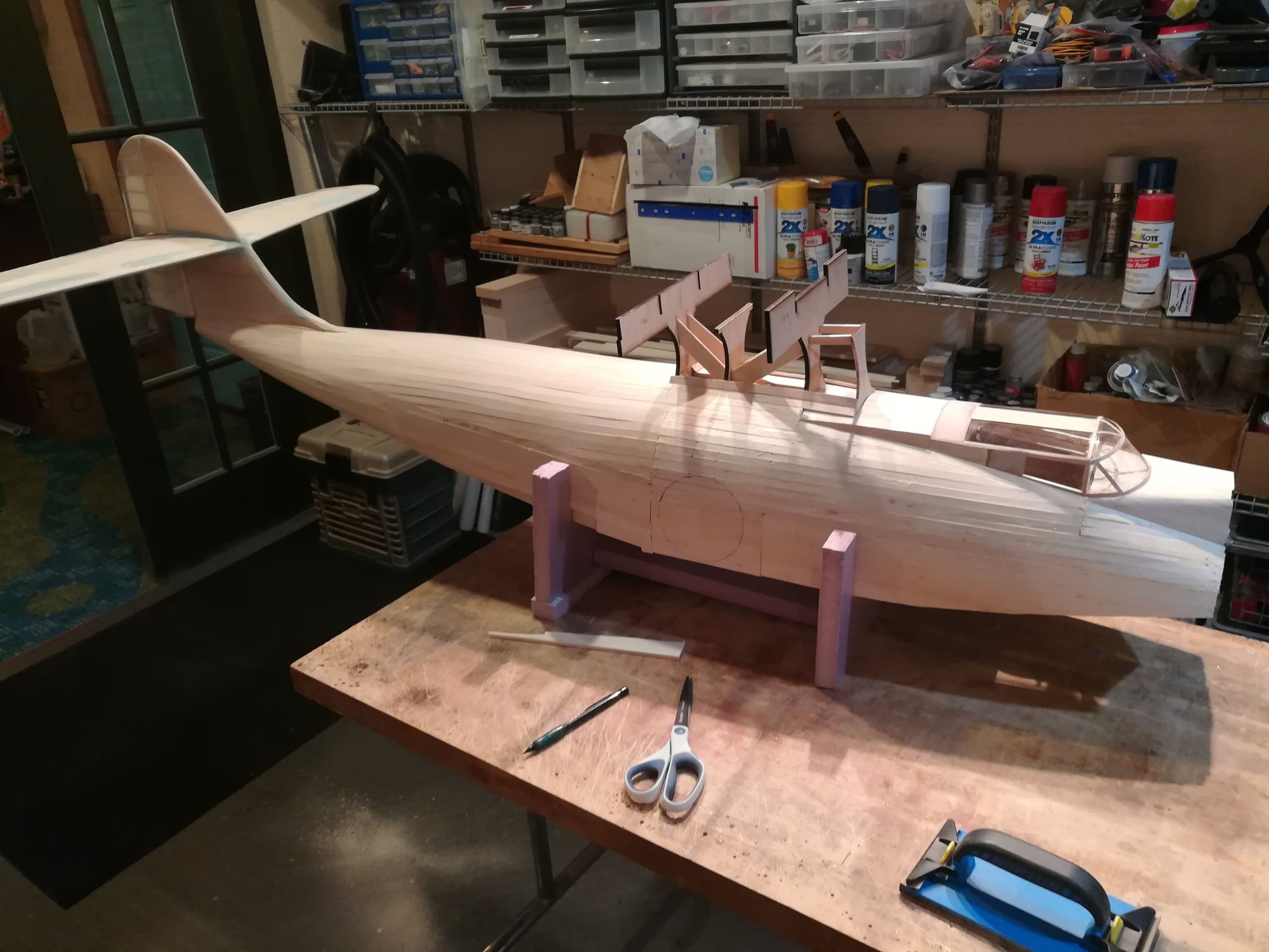
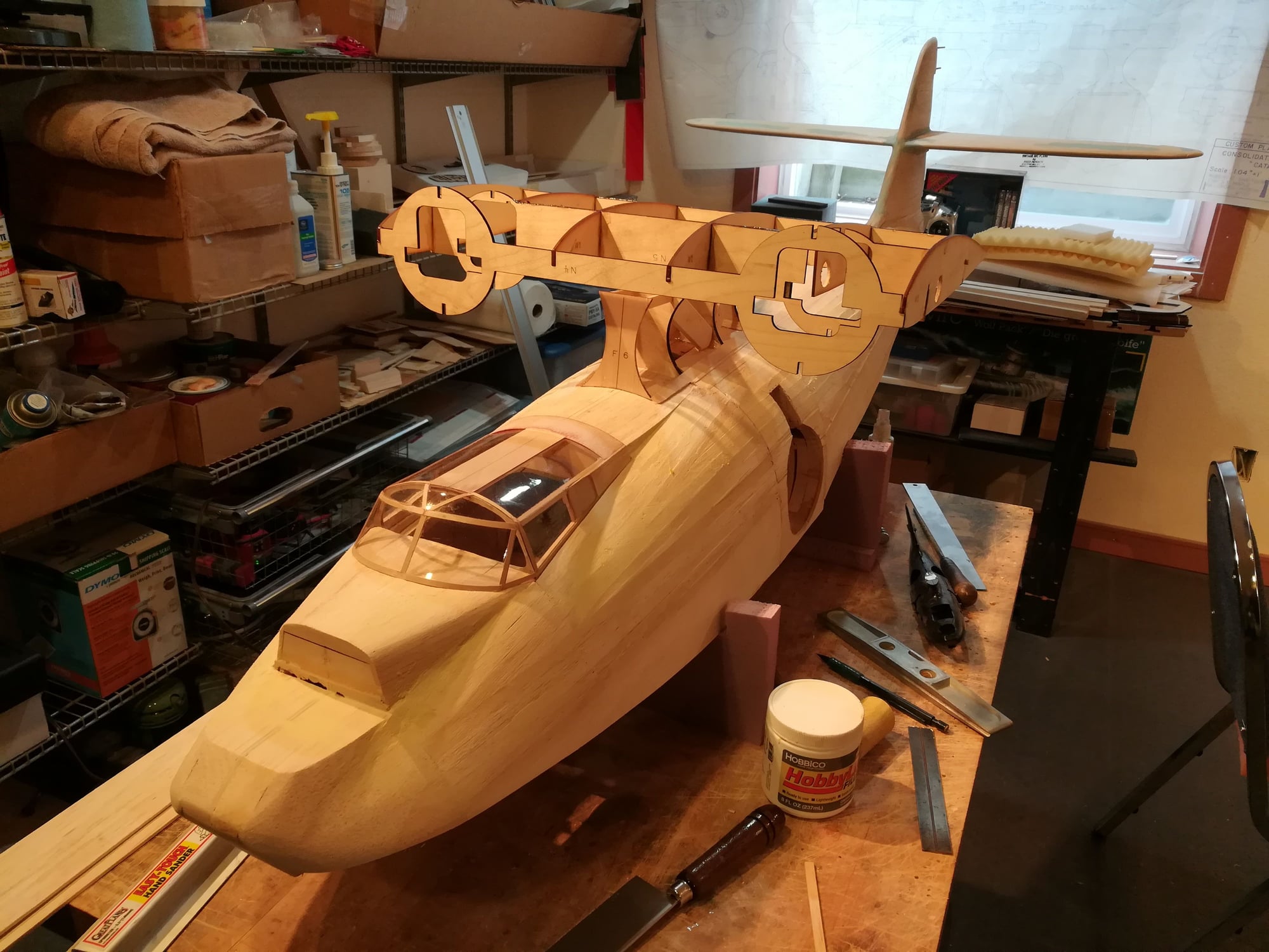
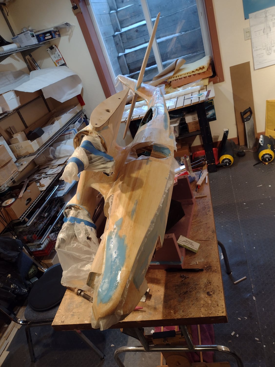
I've been sanding out the fuse. It's starting too look pretty good. I really like the shape of this fuse. It just seems like it belongs on the water.
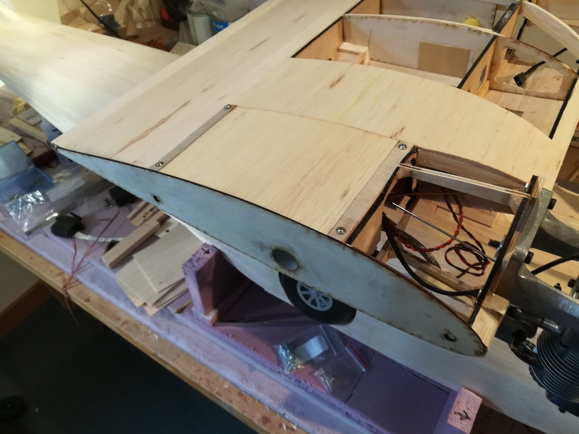
I've also cut the other wheel well out. I'll be reinstalling the retracts and testing them again under pressure to insure that everything clears properly.
I've also cut the other wheel well out. I'll be reinstalling the retracts and testing them again under pressure to insure that everything clears properly.
03-08-2020, 01:40 PM
#89
Senior Member
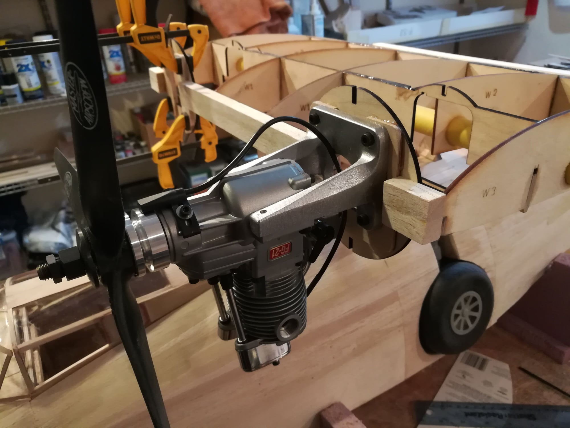
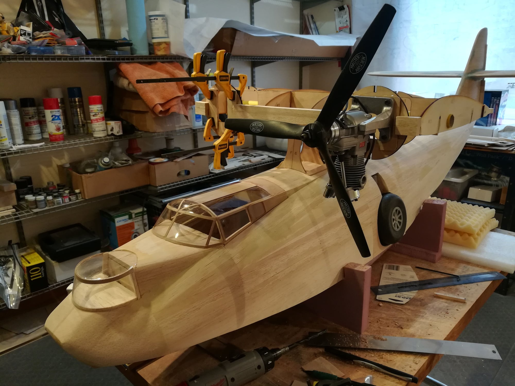
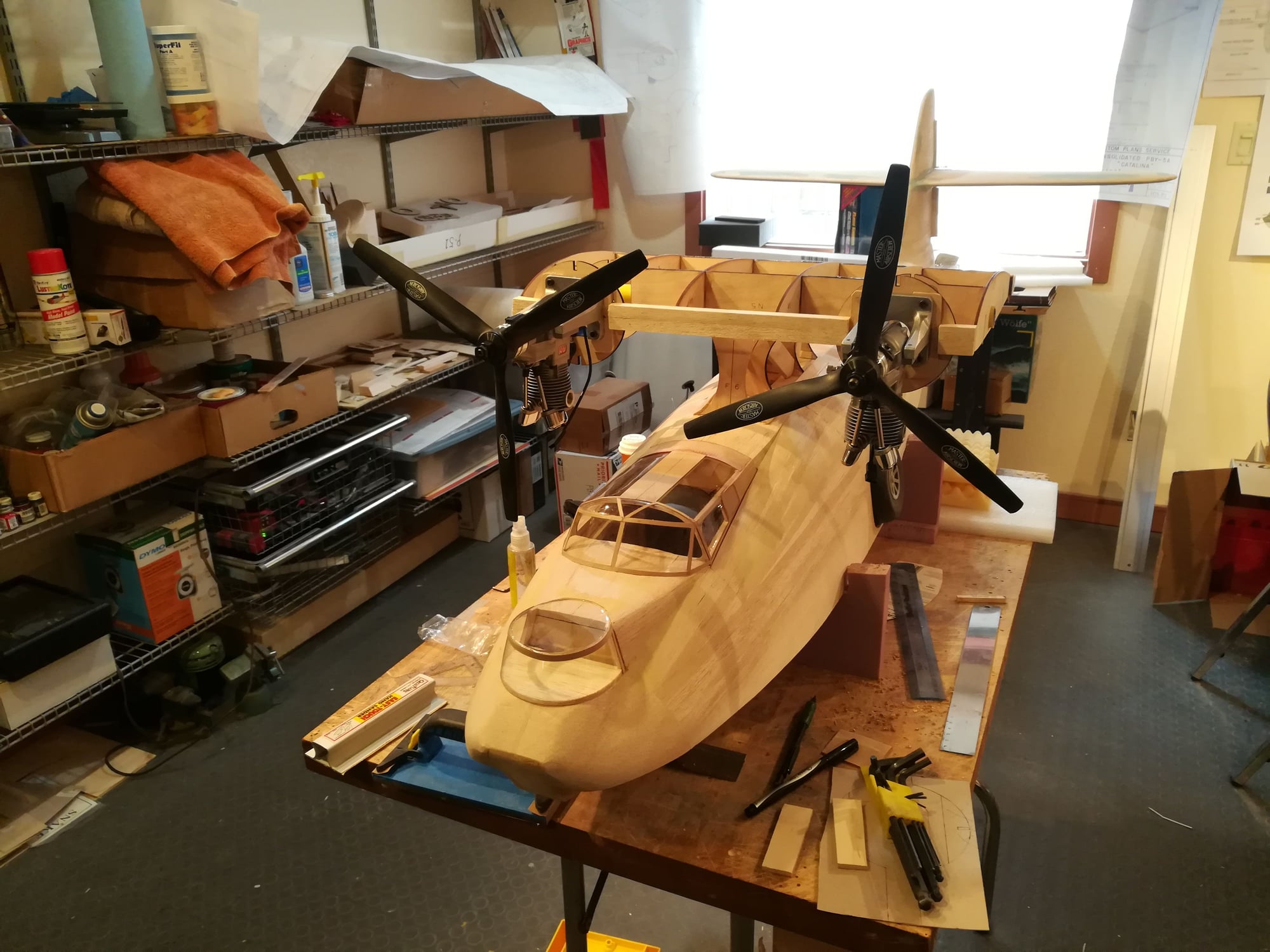
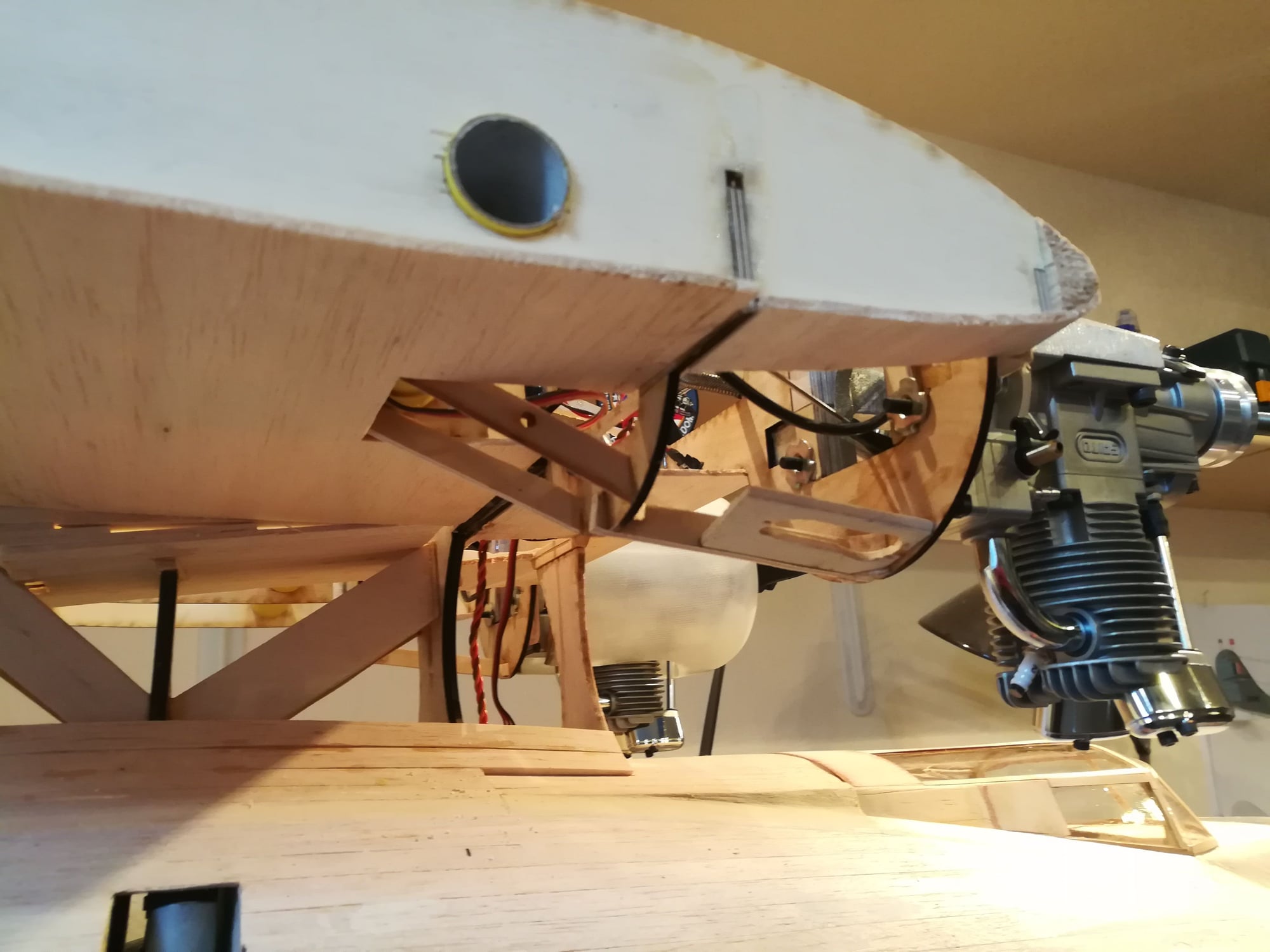
Mounted the engines. These are Saito FG-21s. I will be turning 13x8 3-bladed MAS props. The engines came with nice aluminum mounts, which i chose to use instead of the hardwood rails. The engines are set at 2 degrees to the outside (i.e. left engine has 2 degrees left thrust, right engine has 2 degrees right thrust). I will need to tie the firewall to the main spar, but that will come next.
10-18-2020, 04:25 PM
#90
Senior Member
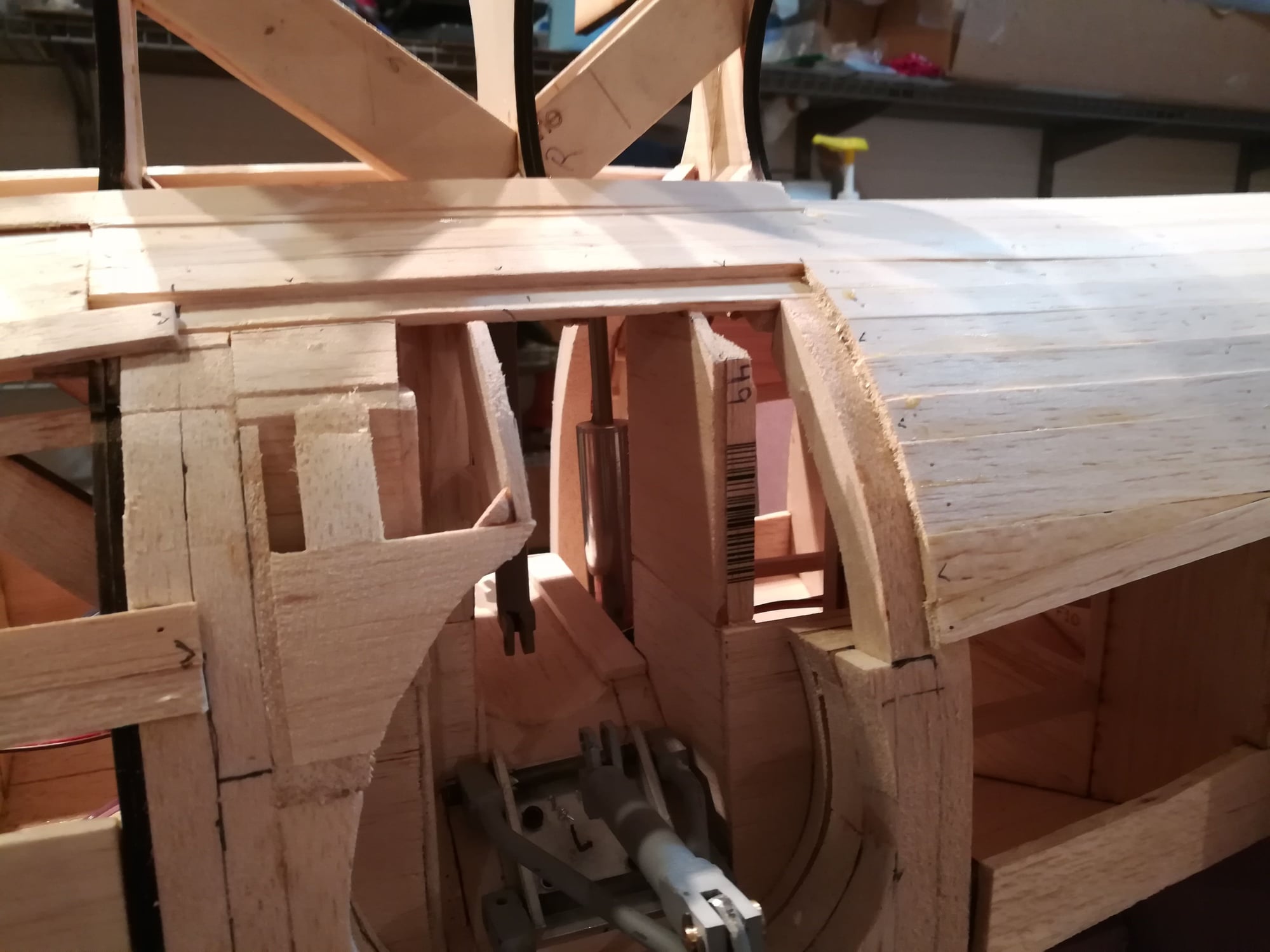
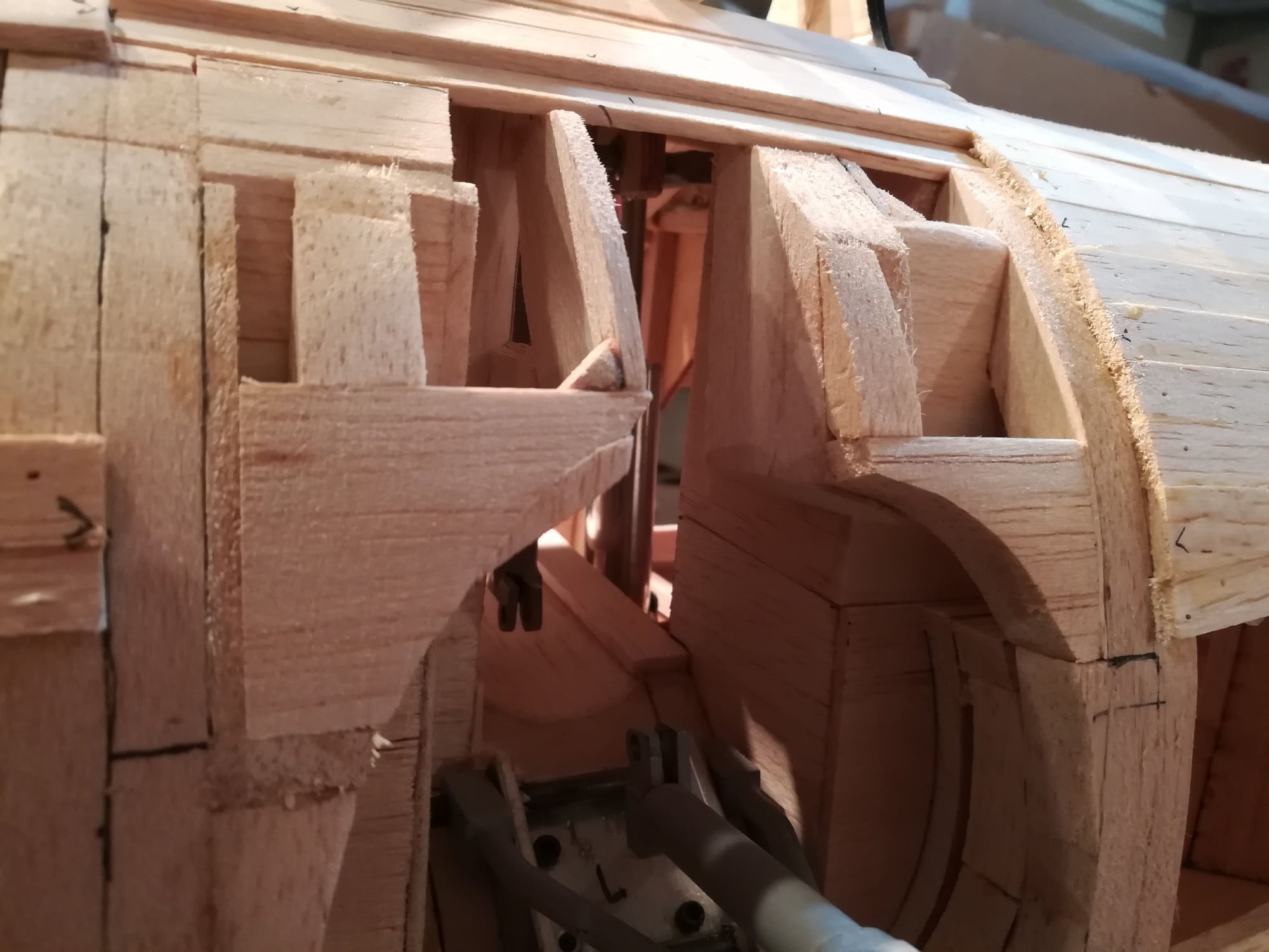
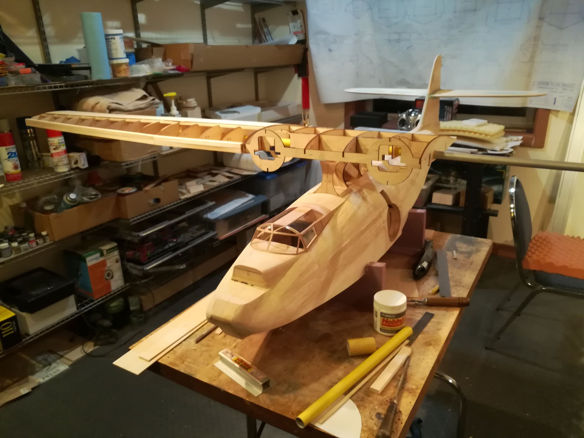
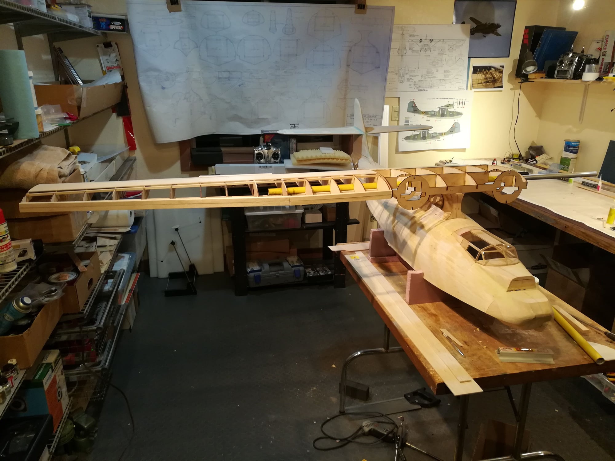
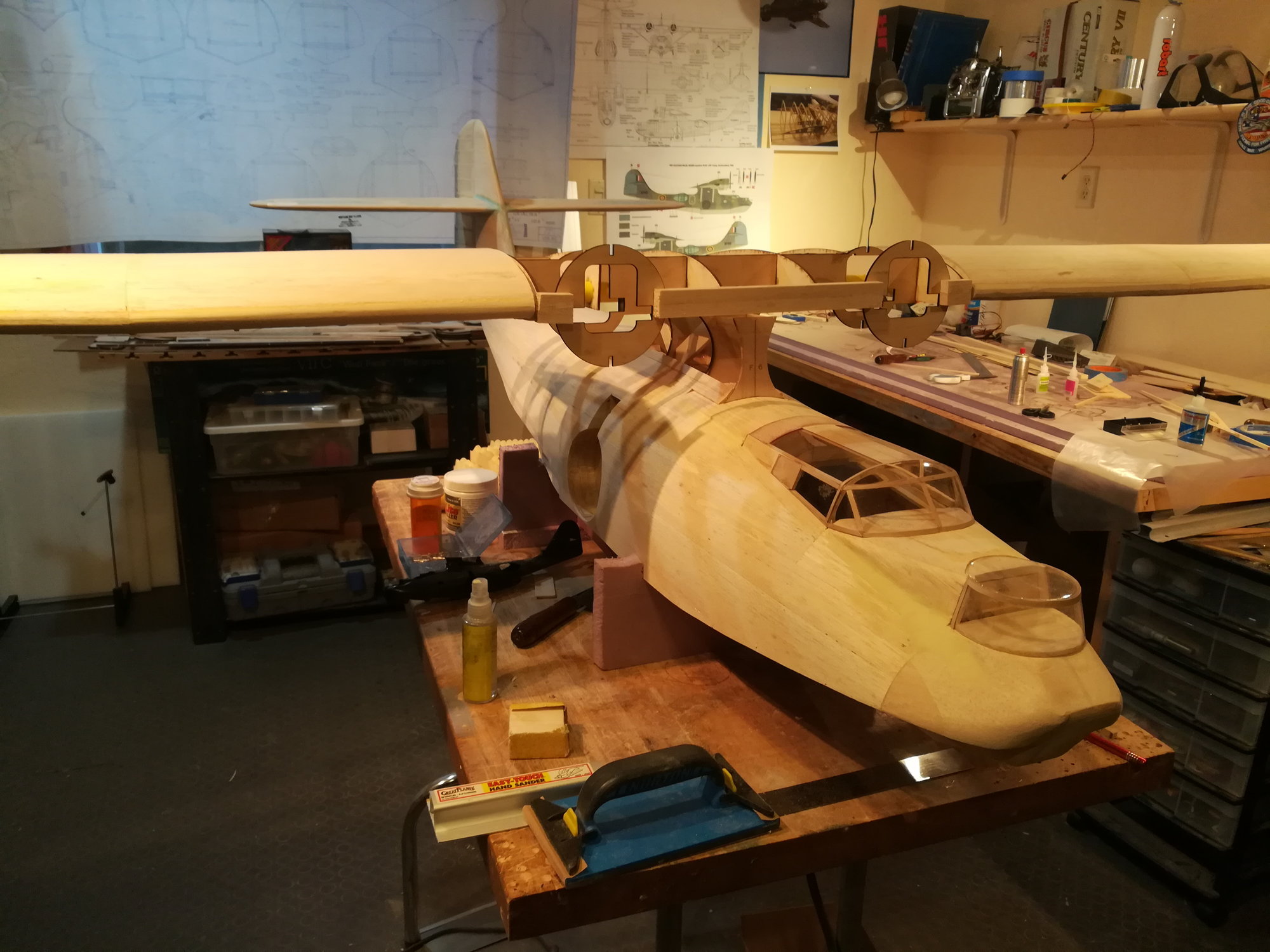
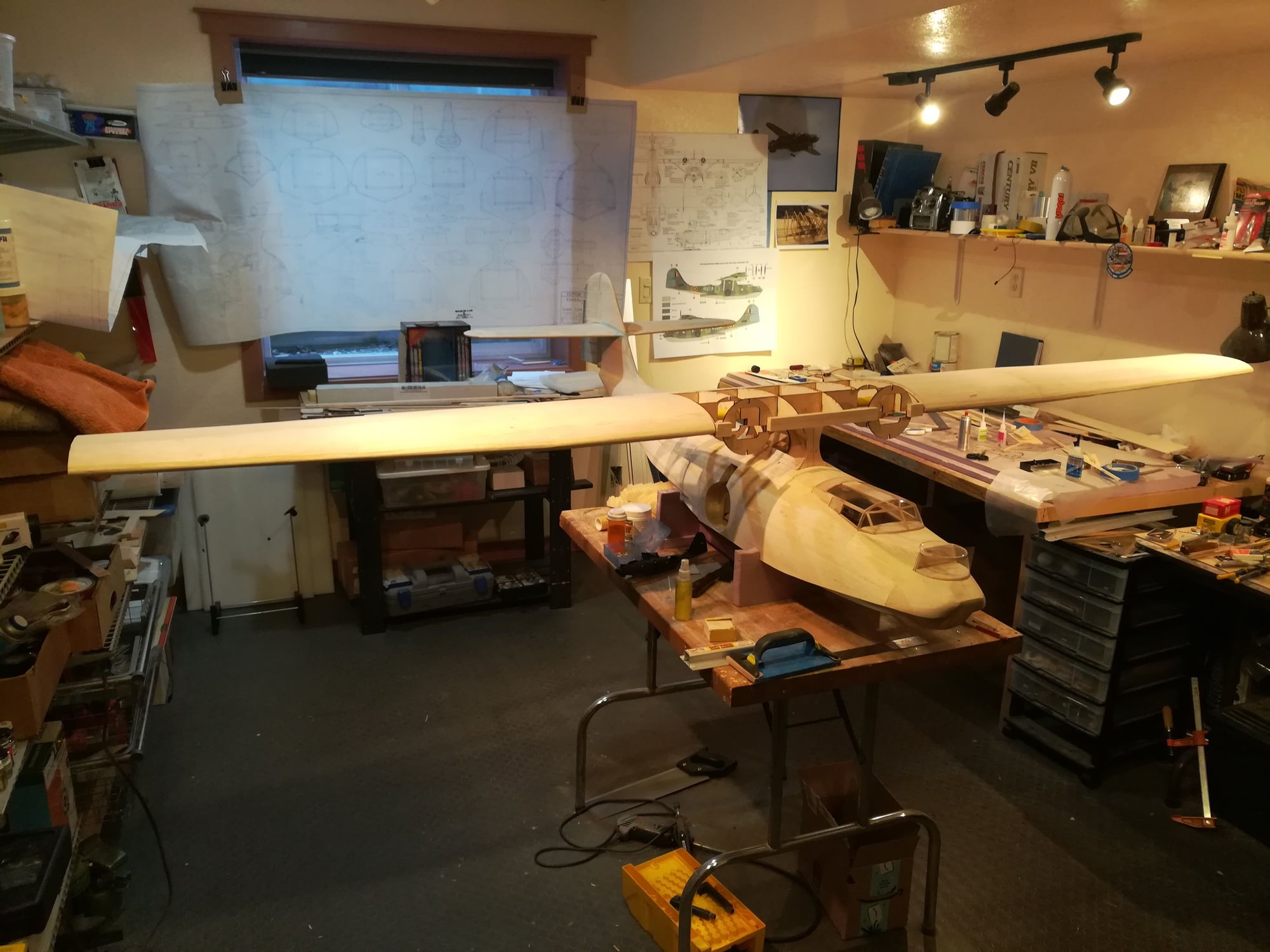
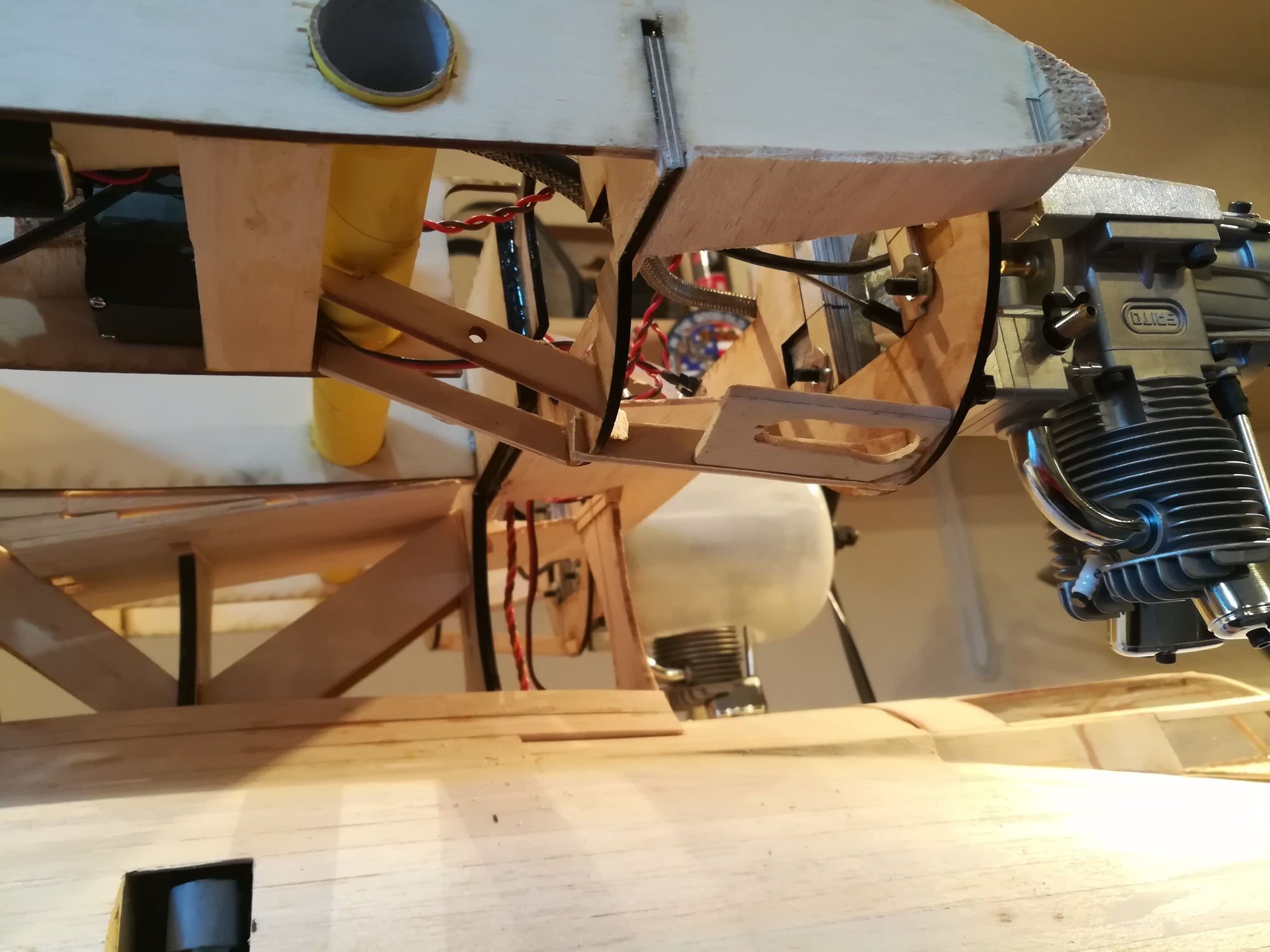
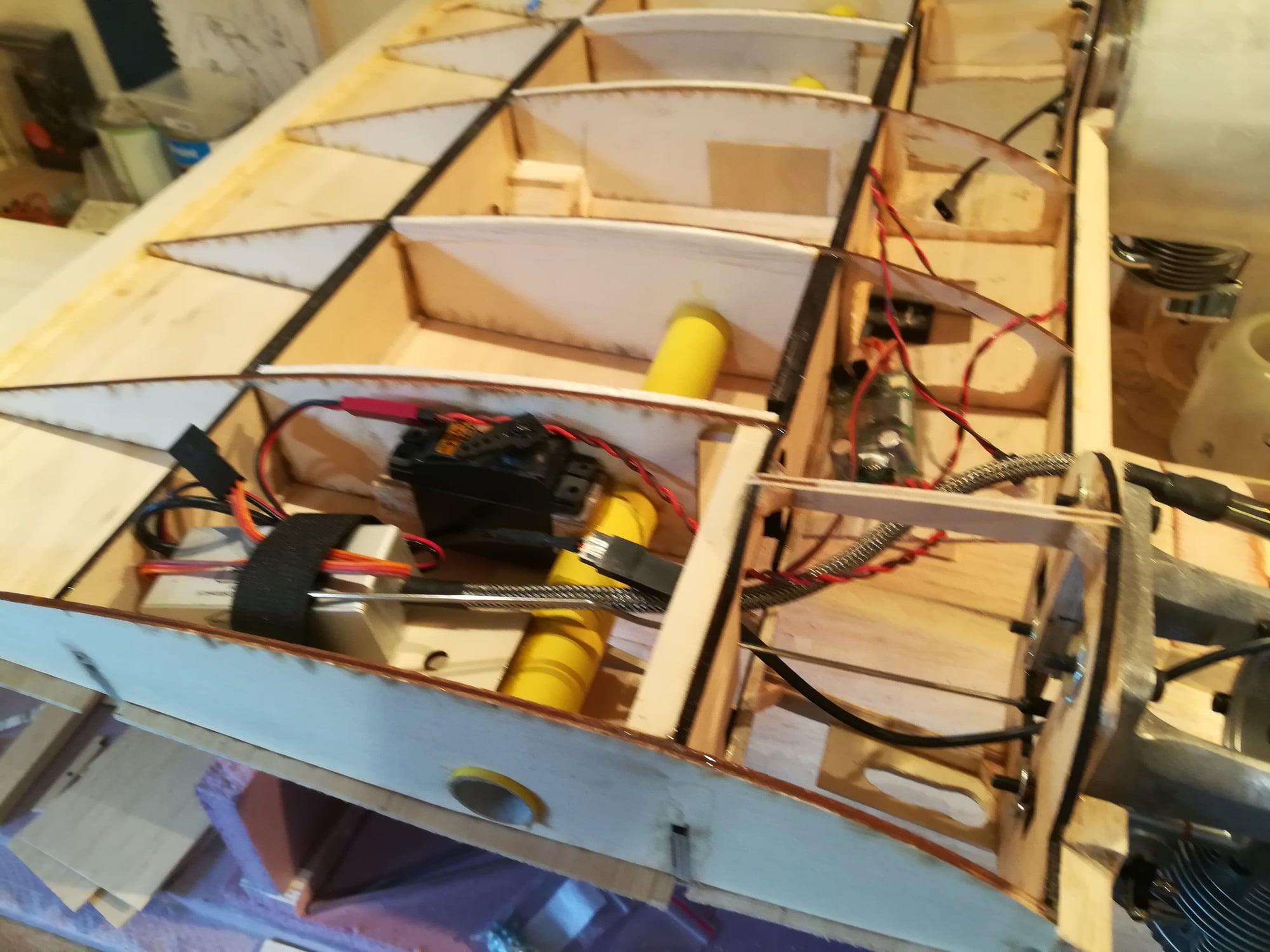
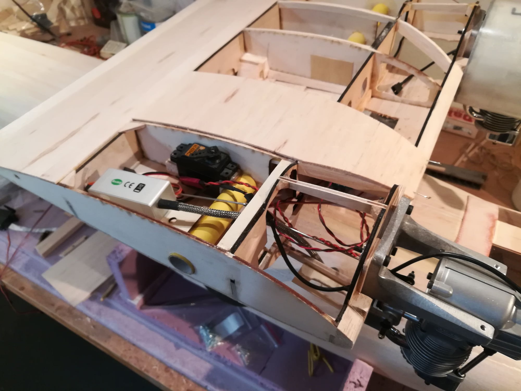
With the summer flying season over, picking up work on the PBY. There will be 3 hatches on the top of the wing. One each for engine ignition, servo, etc. and One for the fuel tanks. This is necessitated by the oversized engine that has been installed.
Additional bracing has been installed between the firewall and ply wing ribs.
Work on sheeting the wing and planking the right nacell.
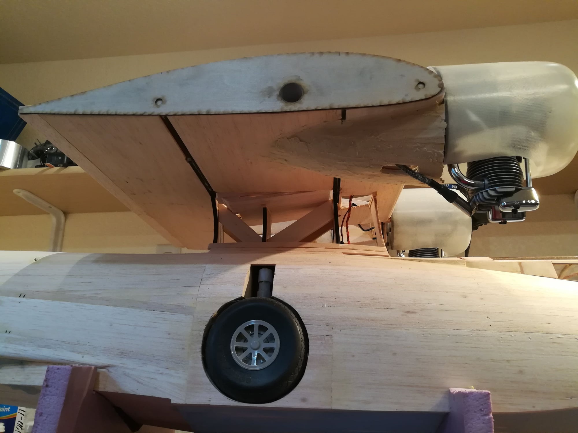
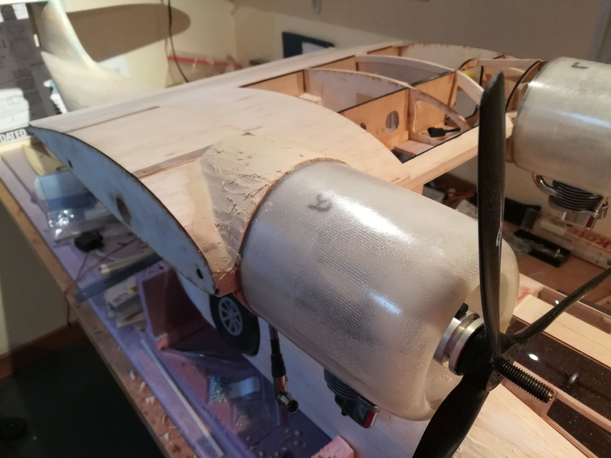
Additional bracing has been installed between the firewall and ply wing ribs.
Work on sheeting the wing and planking the right nacell.
02-20-2021, 04:00 PM
#91
Senior Member
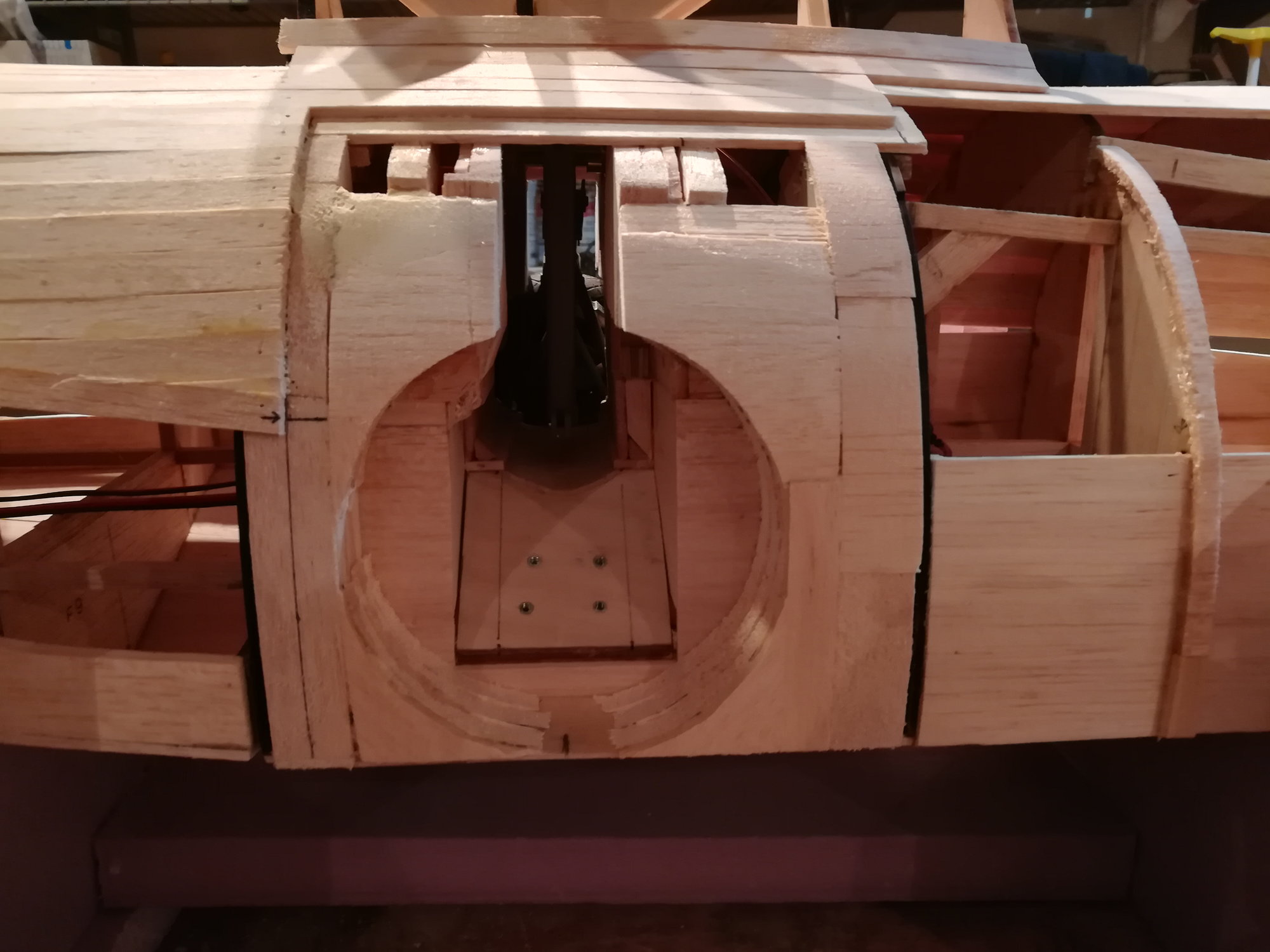
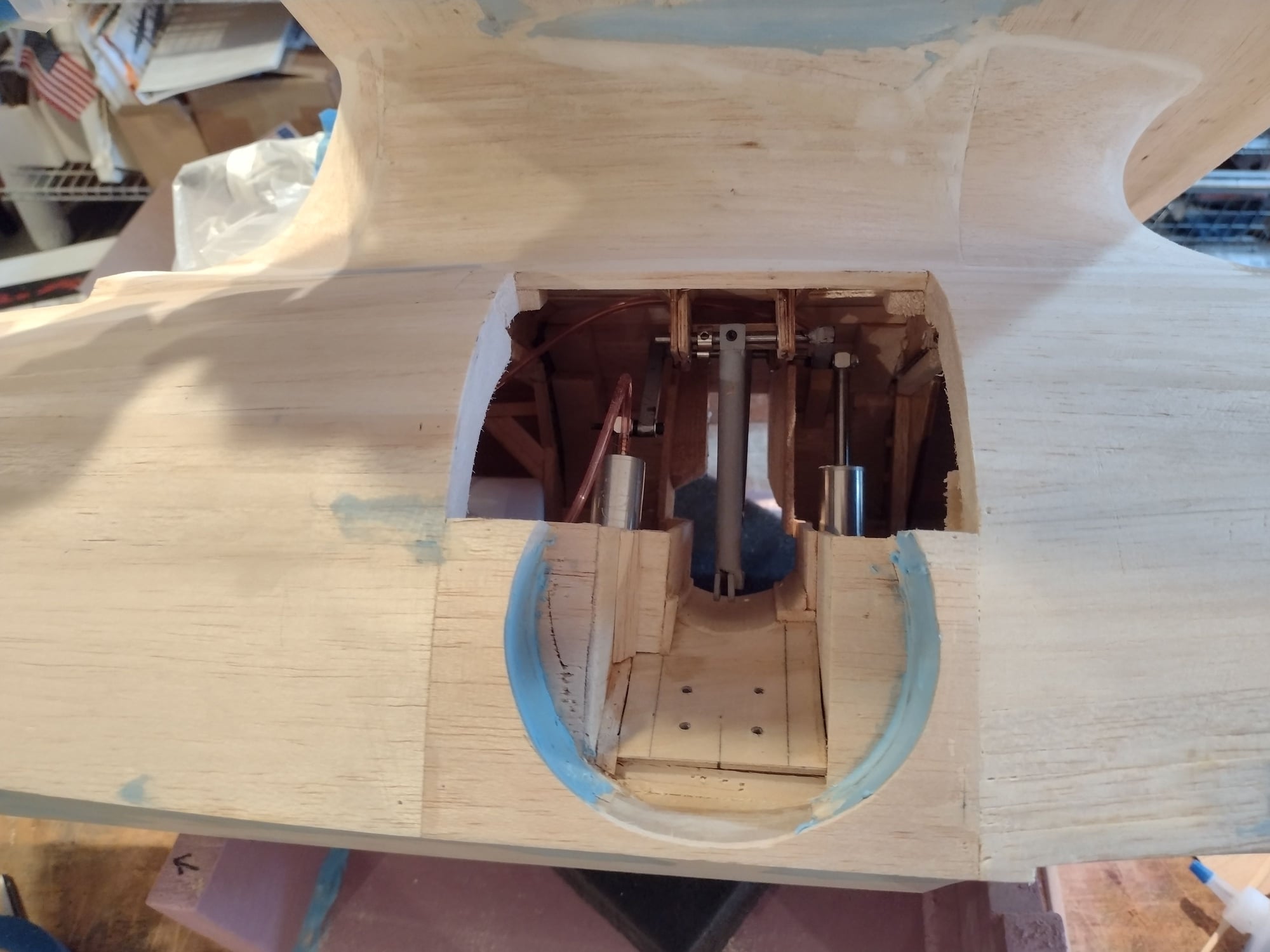
The build of the core of the plane is nearing completion. Cut outs for the observation bubbles. Finally cut free the "hatch" to be able to do maintenance on the retracts. There is also a hatch between the two bubbles. this will be the main hatch for switch, charging, air.

 03-03-2021, 02:57 PM
#93

Join Date: Dec 2002
Location: Thurso, UNITED KINGDOM
Posts: 895
Likes: 0
Received 0 Likes
on
0 Posts
Hi
I am shortly going to start building the same plane. I have the same retracts, I was going to make a dummy centre sectin so I could play with the retracts and get the best munting solution before i stumbed on your thread ( very nice work) . Any chance you could possibly give more details of how you have the main retracts mounted, eg mounting plate angle etc and any modifications you made?
Thanks
Mike
03-04-2021, 05:23 PM
#94
Senior Member
Hi
I am shortly going to start building the same plane. I have the same retracts, I was going to make a dummy centre sectin so I could play with the retracts and get the best munting solution before i stumbed on your thread ( very nice work) . Any chance you could possibly give more details of how you have the main retracts mounted, eg mounting plate angle etc and any modifications you made?
Thanks
Mike
I am shortly going to start building the same plane. I have the same retracts, I was going to make a dummy centre sectin so I could play with the retracts and get the best munting solution before i stumbed on your thread ( very nice work) . Any chance you could possibly give more details of how you have the main retracts mounted, eg mounting plate angle etc and any modifications you made?
Thanks
Mike
Mike, I'll try and provide some additional guidance. But, if you review the beginning of this thread you will see lots of picts and description of what I did to get the gear in.
As for guidance with angles ... can't help here. Don't know about your gear, but mine were clearly made by hand. The two are close, but not identical. So everything I did was custom fitting each gear to the plane.
The first thing to get set is the base plate for the gear (the one with 4 bolt holes). This needs to be set at just the right angle so the wheel sits perpendicular to the ground in both the down and up position. It also needs to be mounted just high enough in the fuse so that when the wheel is retracted that it just clears the floor of the wheel well.
Next you need to locate the position of the torsion bar mount in the fuse. Again, mine were assembled at slightly different angles, so the mount needs to be custom for each side. I used 2 bearings on each one (see pictures earlier). This really made the gear move smoothly. The mount for this will be very high in the fuse. You will want to provide some means to access this for maintenance (see my approach earlier in thread). For my setup, I needed 100% of the travel. I had to shorten the lever that drives the torsion bar (yup, picts of this earlier too
 ).
). As these plans did not consider retracts, you will remove some very real structure from the plane to get the gear in. Clearly, this needs to be redesigned to be strong around the wheel wells. Also, you have to think about how the landing loads will be transferred to the fuse. I made additional bracing in the pylon to distribute the load, but it's not the only way.
Let me know what other questions you have, post your progress in a thread or here, and GOOD LUCK.
Joe
03-05-2021, 01:32 PM
#95
Join Date: Dec 2002
Location: Thurso, UNITED KINGDOM
Posts: 895
Likes: 0
Received 0 Likes
on
0 Posts
Hi Joe
Looks like I am back to plan A, build a mock up of the centre section and use it to work out the installation before I build the real things.
thank for documenting a very interesting build
Looks like I am back to plan A, build a mock up of the centre section and use it to work out the installation before I build the real things.
thank for documenting a very interesting build
03-07-2021, 03:57 AM
#96
My Feedback: (6)
Join Date: Aug 2002
Location: Columbia, MD
Posts: 687
Likes: 0
Received 0 Likes
on
0 Posts
A friend has this plane that he purchased already built with glow engines. He wants to convert it to electric. One of the things needed to determine the motors, props and ESC is the weight of the model.
1. What is the approximate flying weight of this model?
2. What is the maximum prop size that can be used on this model?
-Vic
1. What is the approximate flying weight of this model?
2. What is the maximum prop size that can be used on this model?
-Vic
03-07-2021, 04:19 PM
#97
Senior Member
A friend has this plane that he purchased already built with glow engines. He wants to convert it to electric. One of the things needed to determine the motors, props and ESC is the weight of the model.
1. What is the approximate flying weight of this model?
2. What is the maximum prop size that can be used on this model?
-Vic
1. What is the approximate flying weight of this model?
2. What is the maximum prop size that can be used on this model?
-Vic
Props, on mine, I can swing 12" dia prop. any larger and the tips will touch eachother.
Hope this helps.
03-20-2021, 10:51 AM
#98
Senior Member
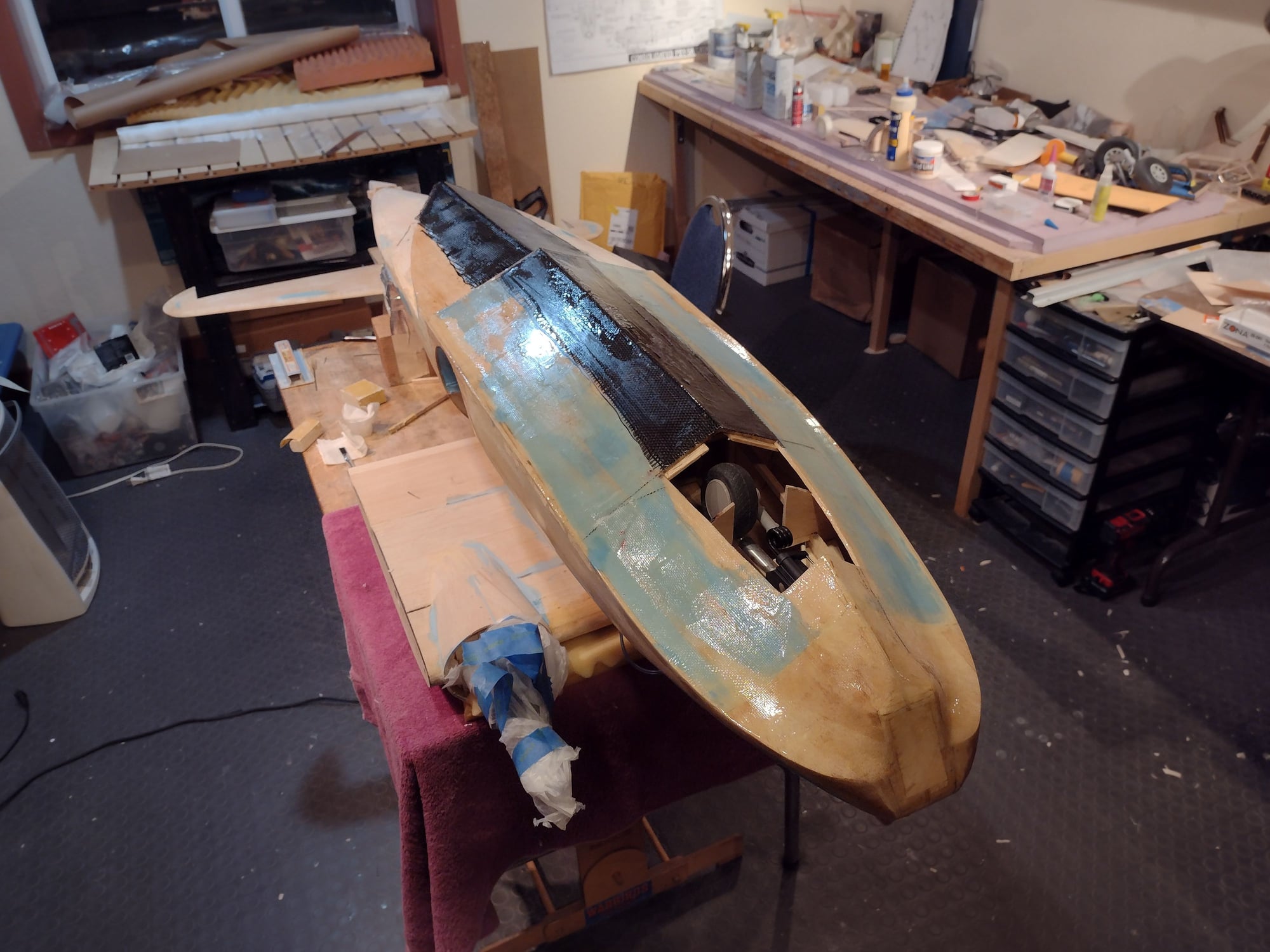
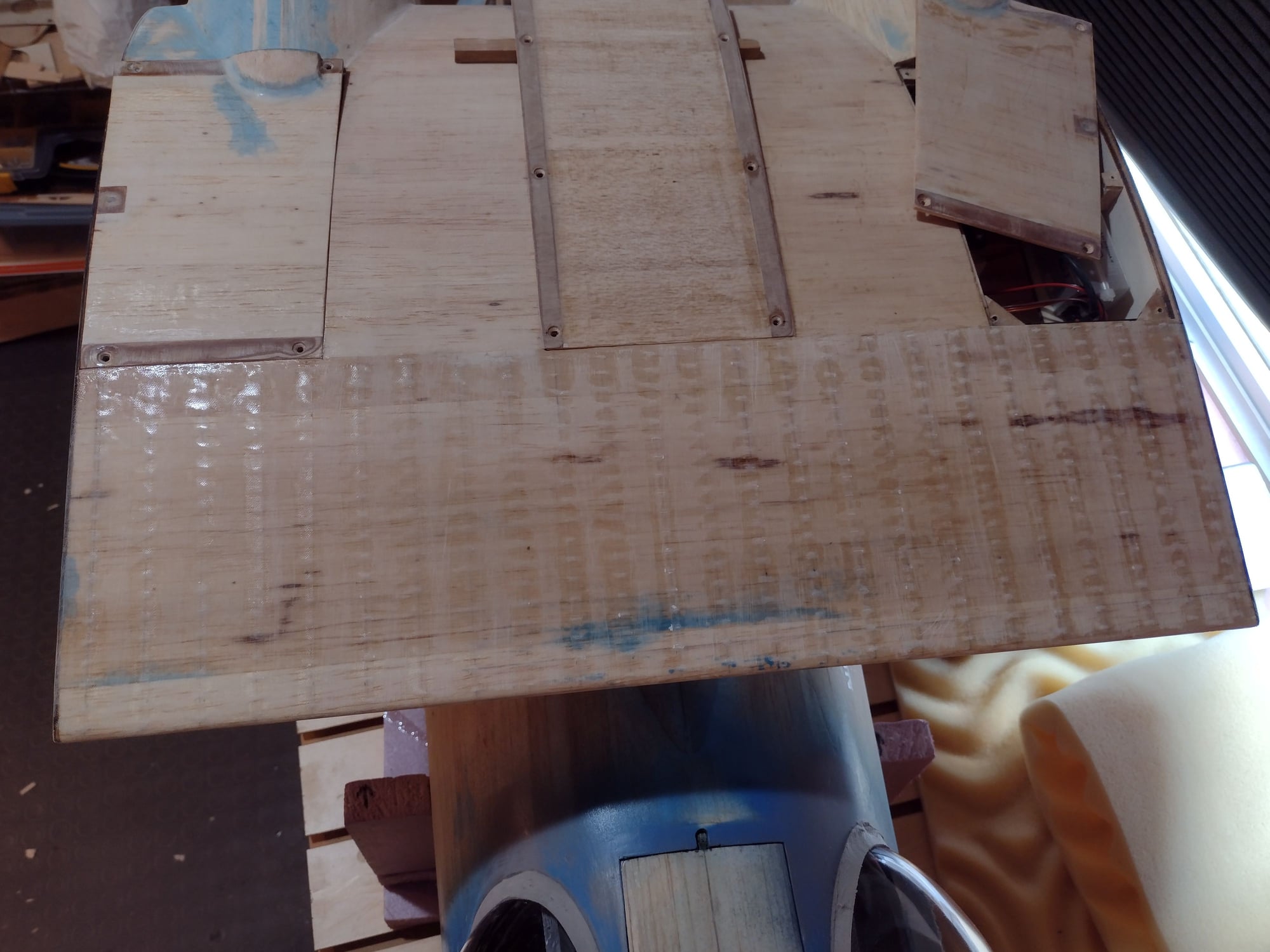
More glassing work on the bottom of the hull.
The forward hull is covered in 6oz fiberglass and 2oz carbon fiber. The rear hull section is covered in 3/4oz fiberglass and 2oz carbon fiber.
Goal here is to have the hull reinforced against hard landing in the water. It will also be quite beneficial to a runway landing where the gear fails to come down.
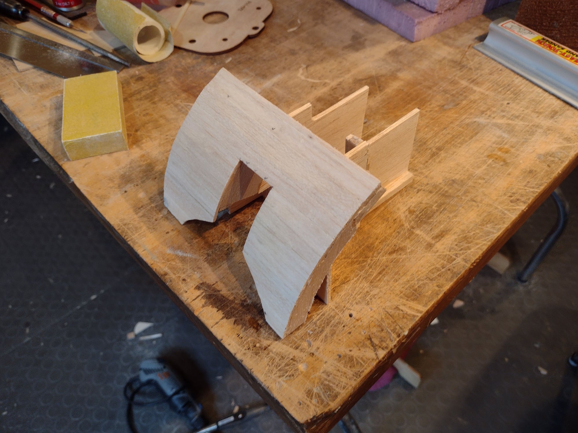
In the 3rd picture you can see the gear doors sitting in place.
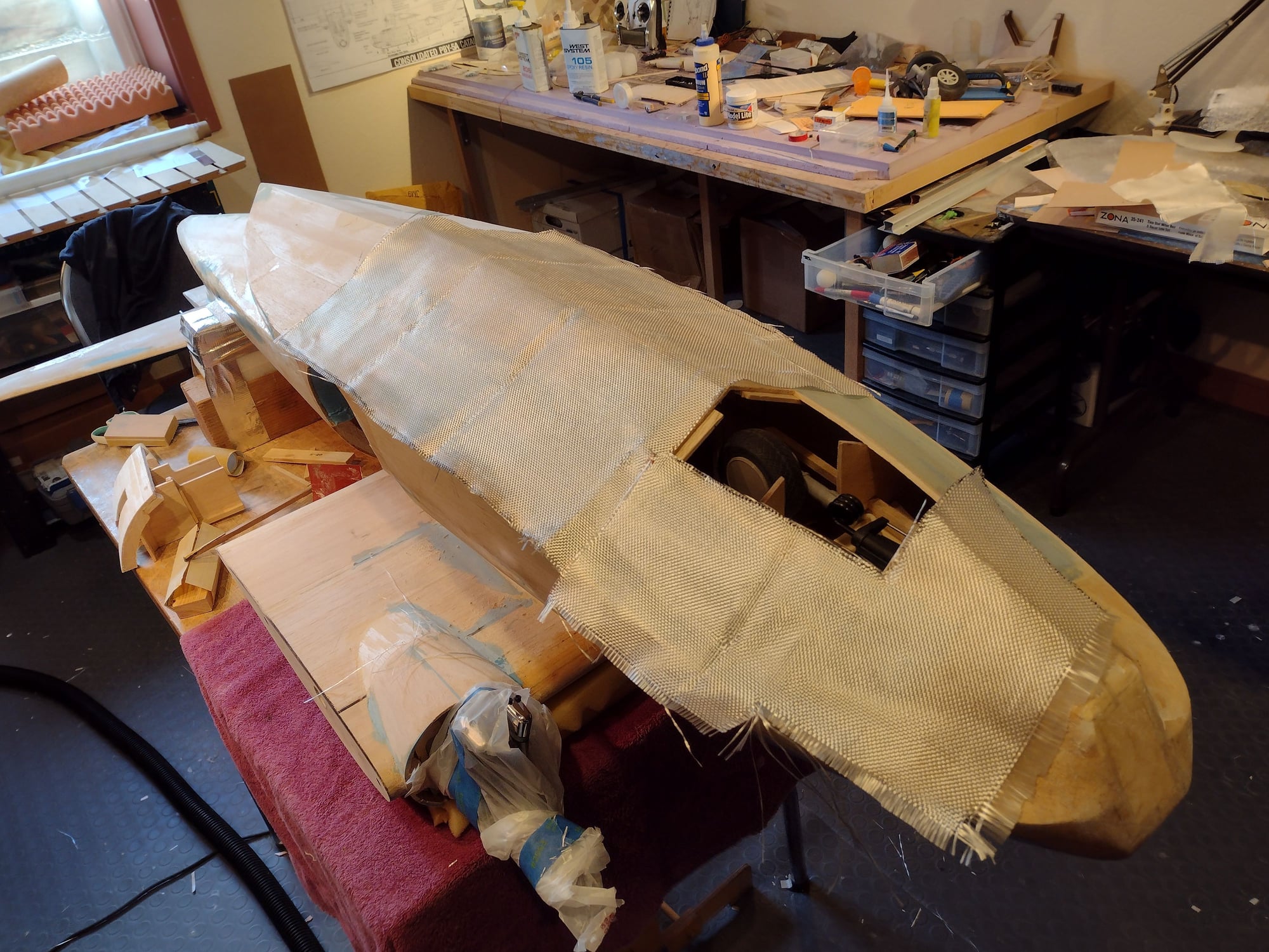
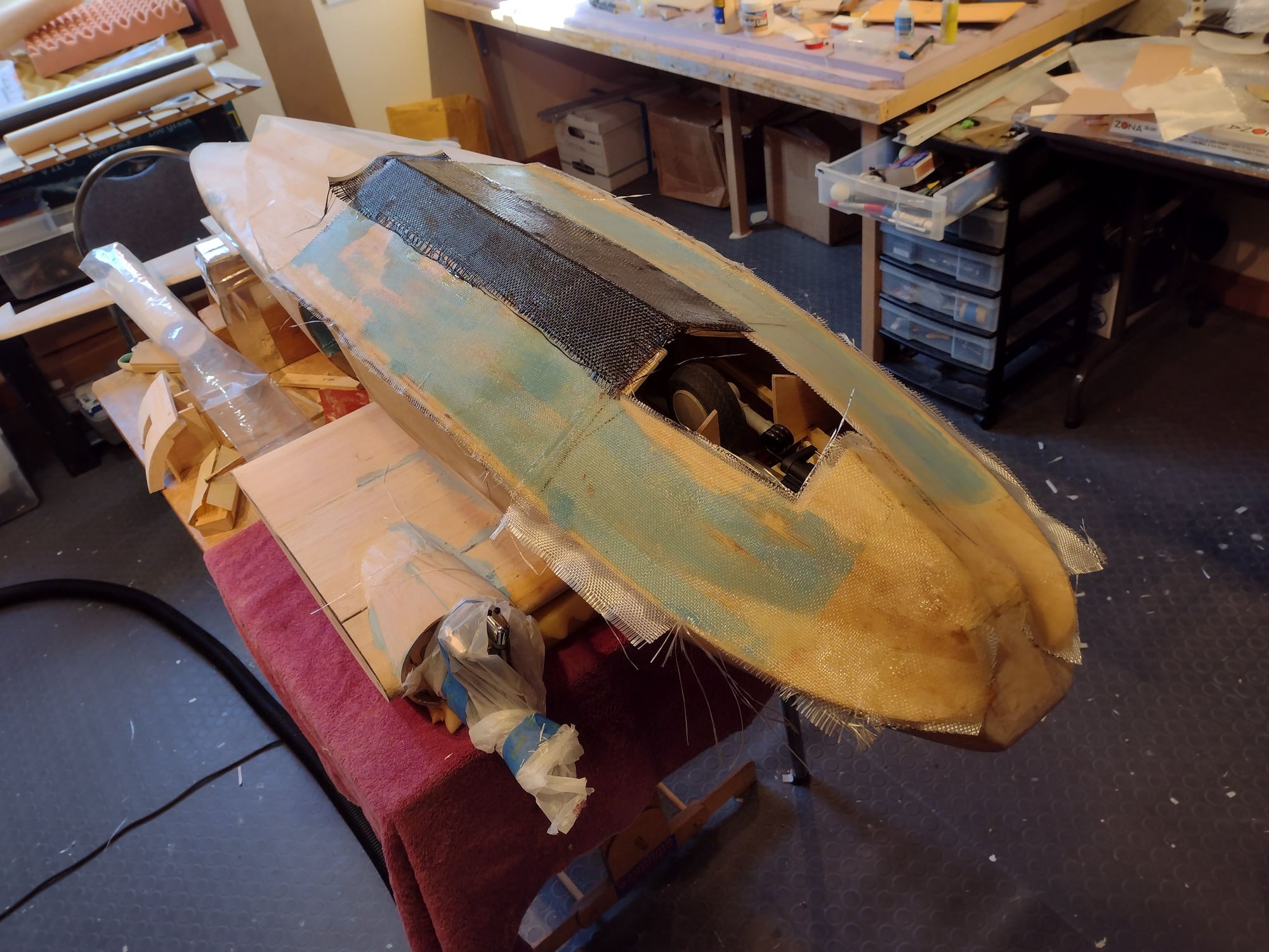
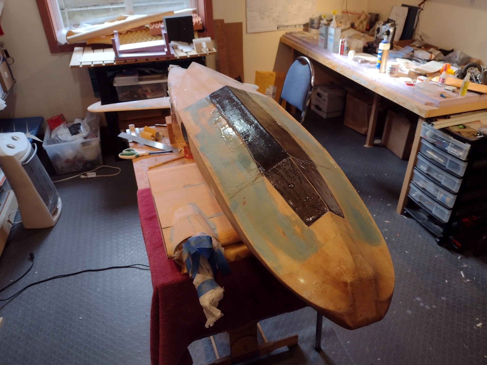
Here you can see the gear doors sitting in place.
The forward hull is covered in 6oz fiberglass and 2oz carbon fiber. The rear hull section is covered in 3/4oz fiberglass and 2oz carbon fiber.
Goal here is to have the hull reinforced against hard landing in the water. It will also be quite beneficial to a runway landing where the gear fails to come down.
In the 3rd picture you can see the gear doors sitting in place.
Here you can see the gear doors sitting in place.
08-10-2021, 05:46 PM
#99
Senior Member
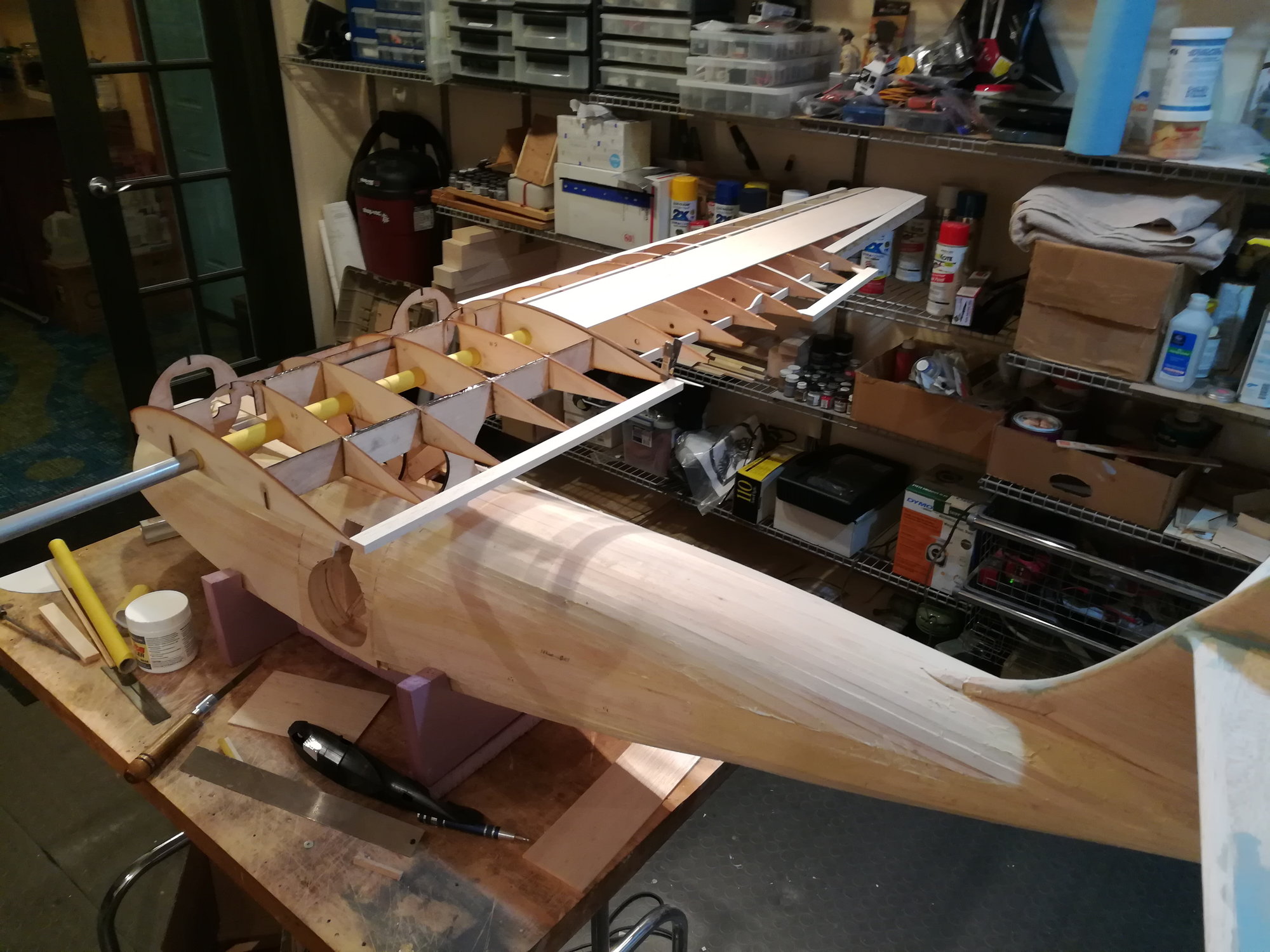
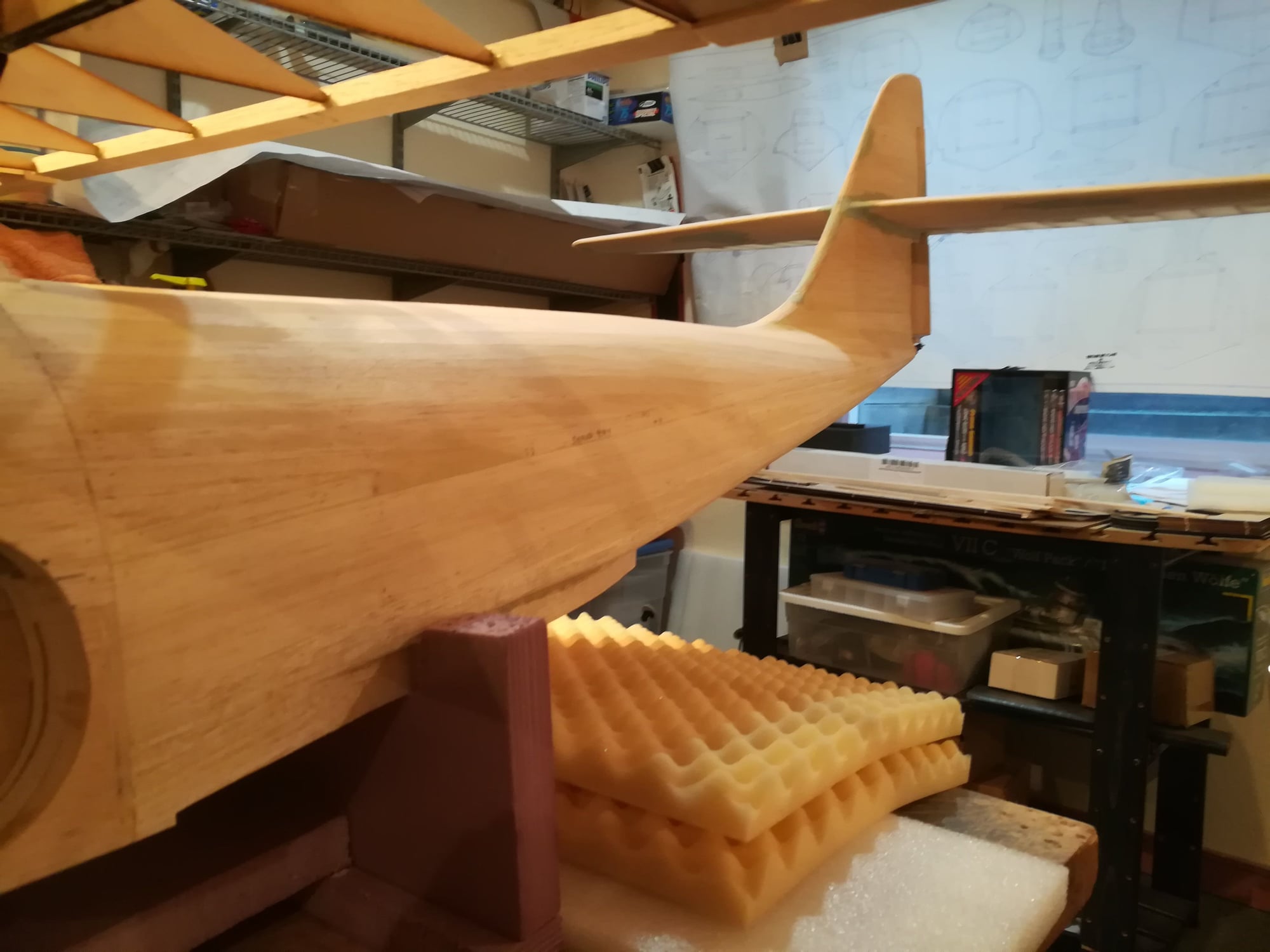
At this point the entire fuse section, tail, and wing center section have been glassed. Tons of sanding and filling.
Added rib stiches to the trailing edge. Here's some of the work.
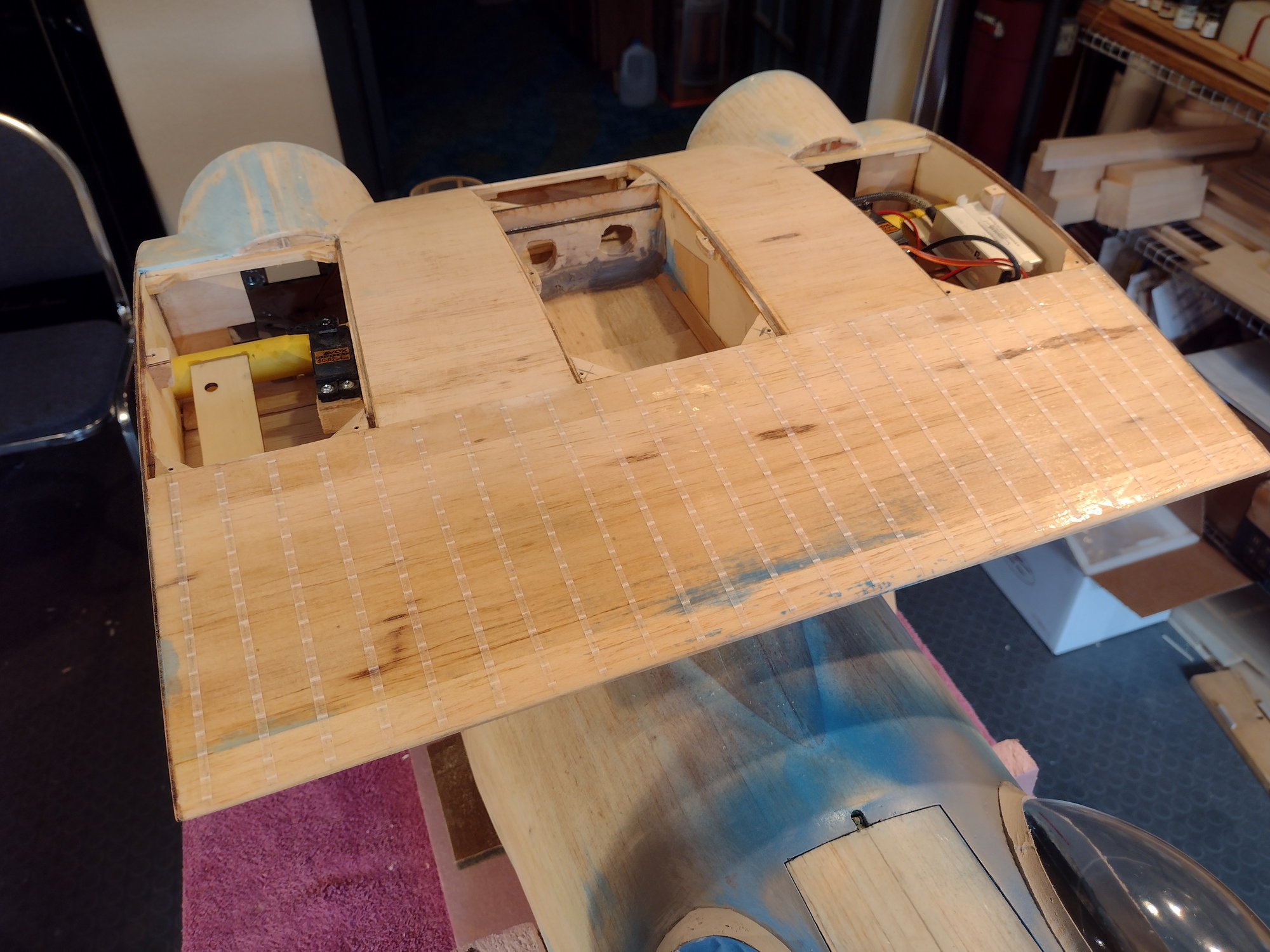
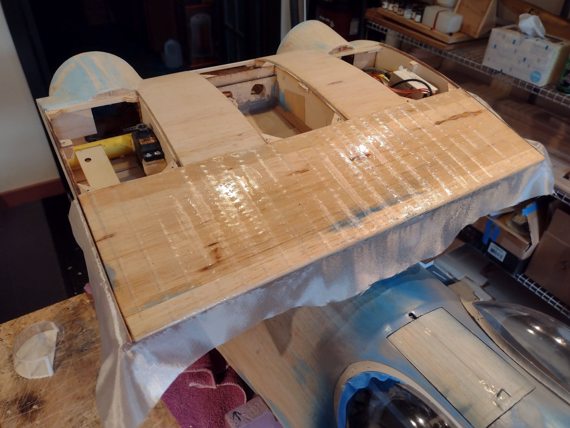
Added rib stiches to the trailing edge. Here's some of the work.
Last edited by Joe-RCBuilder; 08-10-2021 at 05:49 PM.
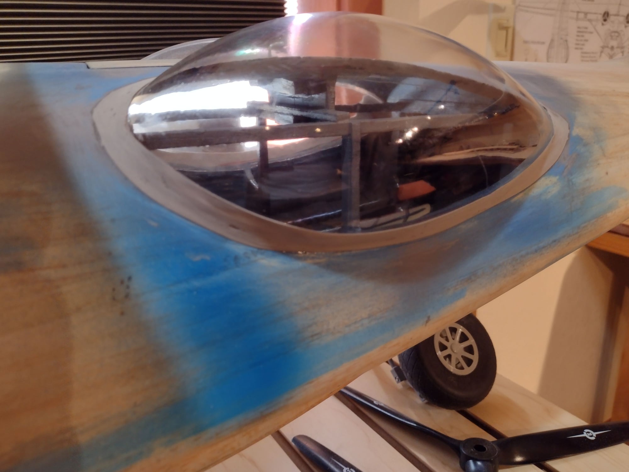
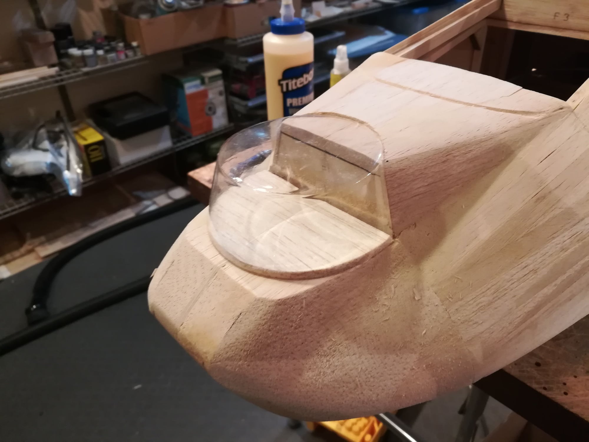
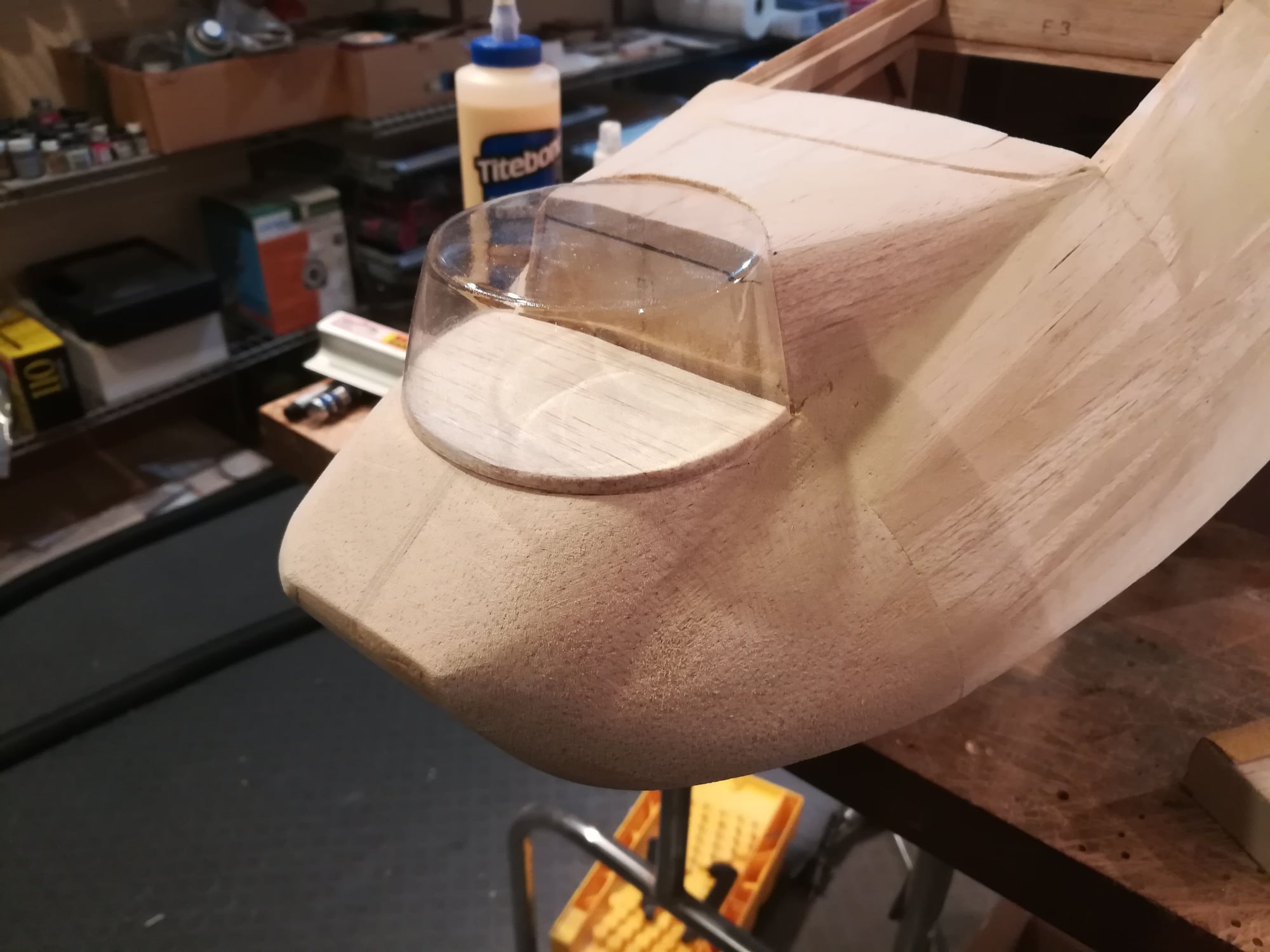
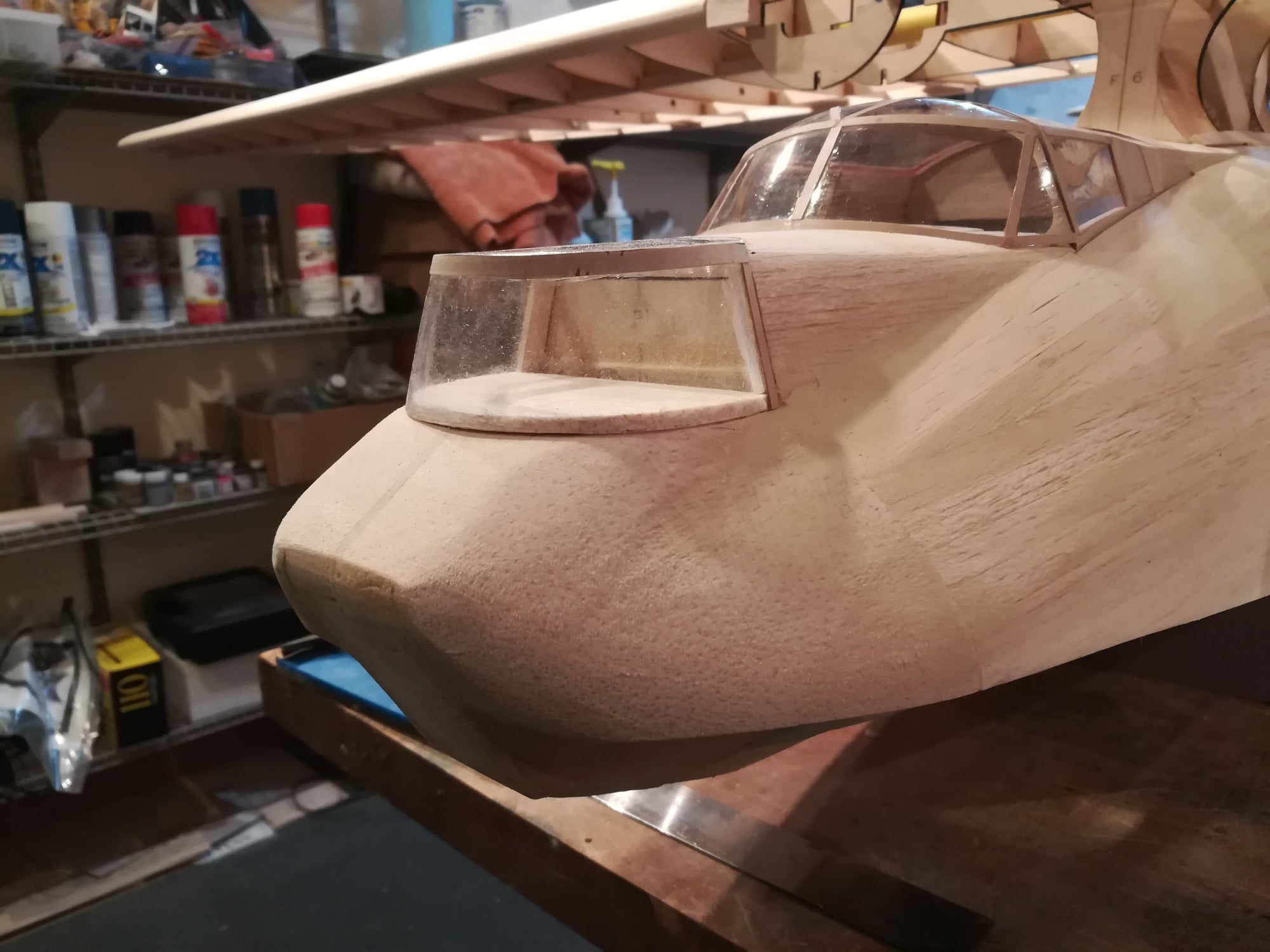
08-10-2021, 05:55 PM
#100
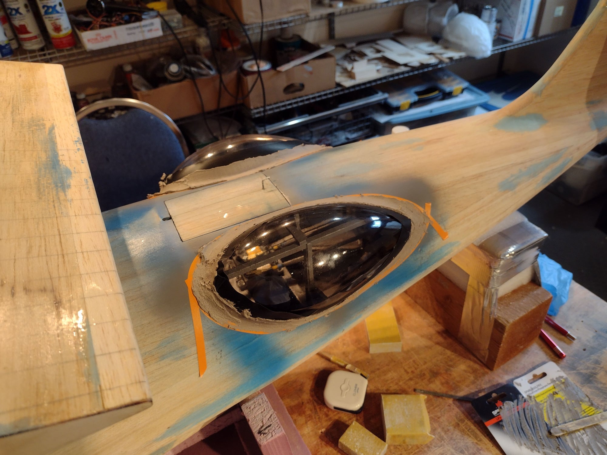
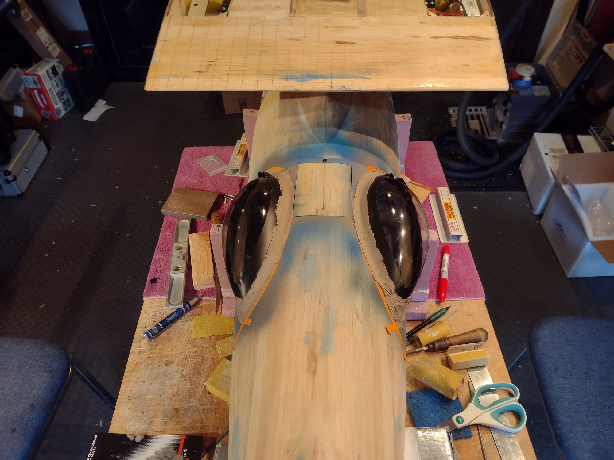
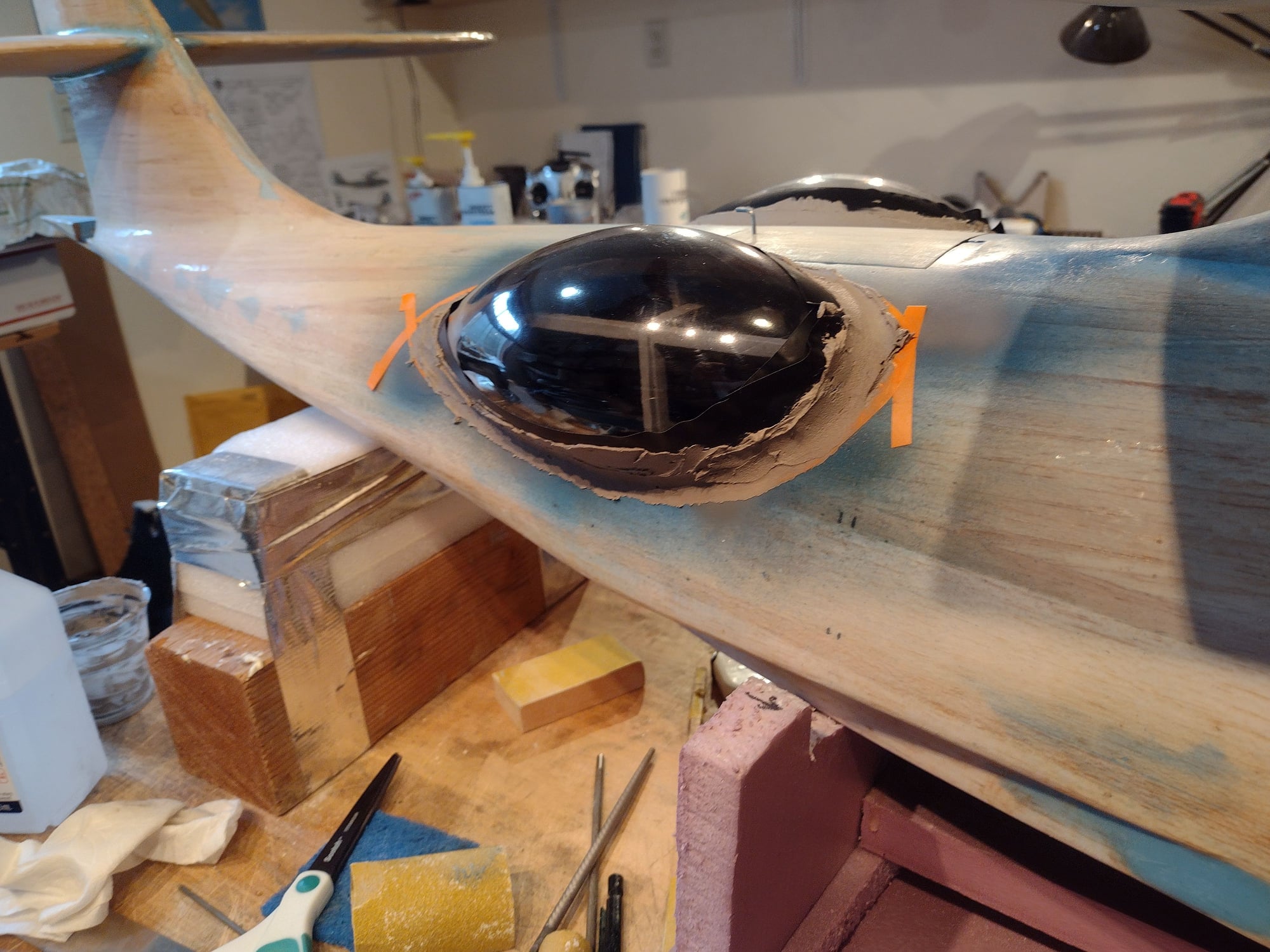
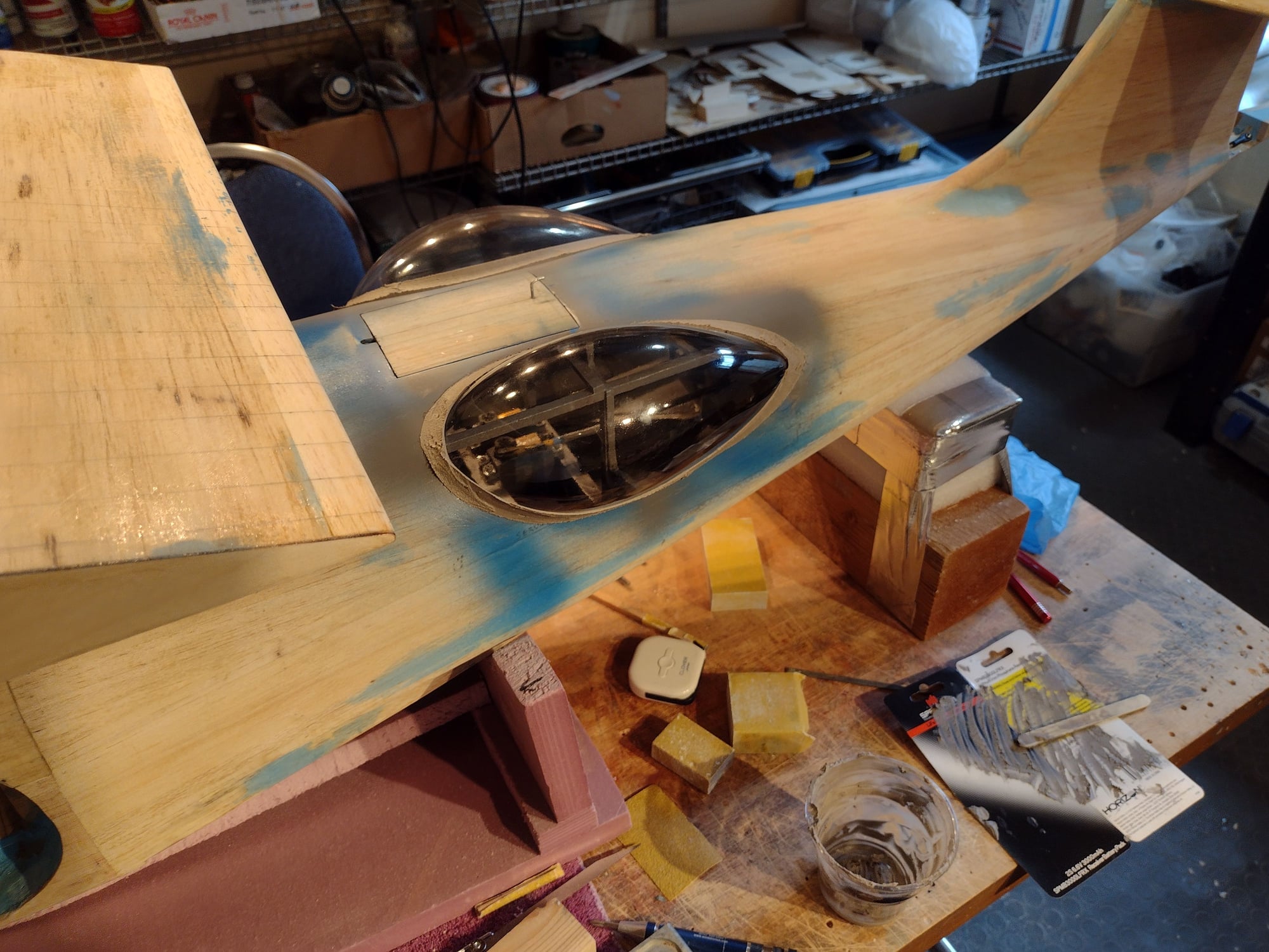
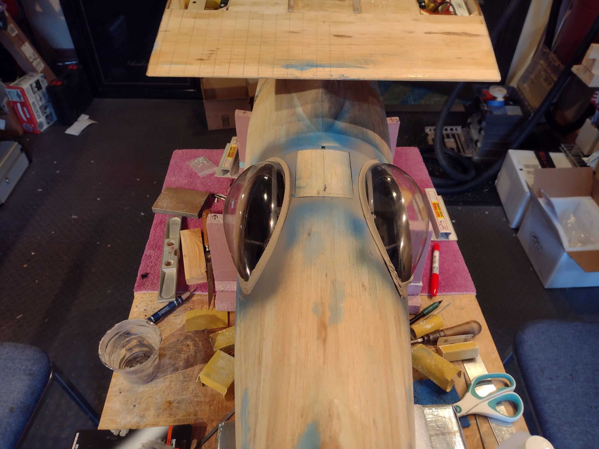
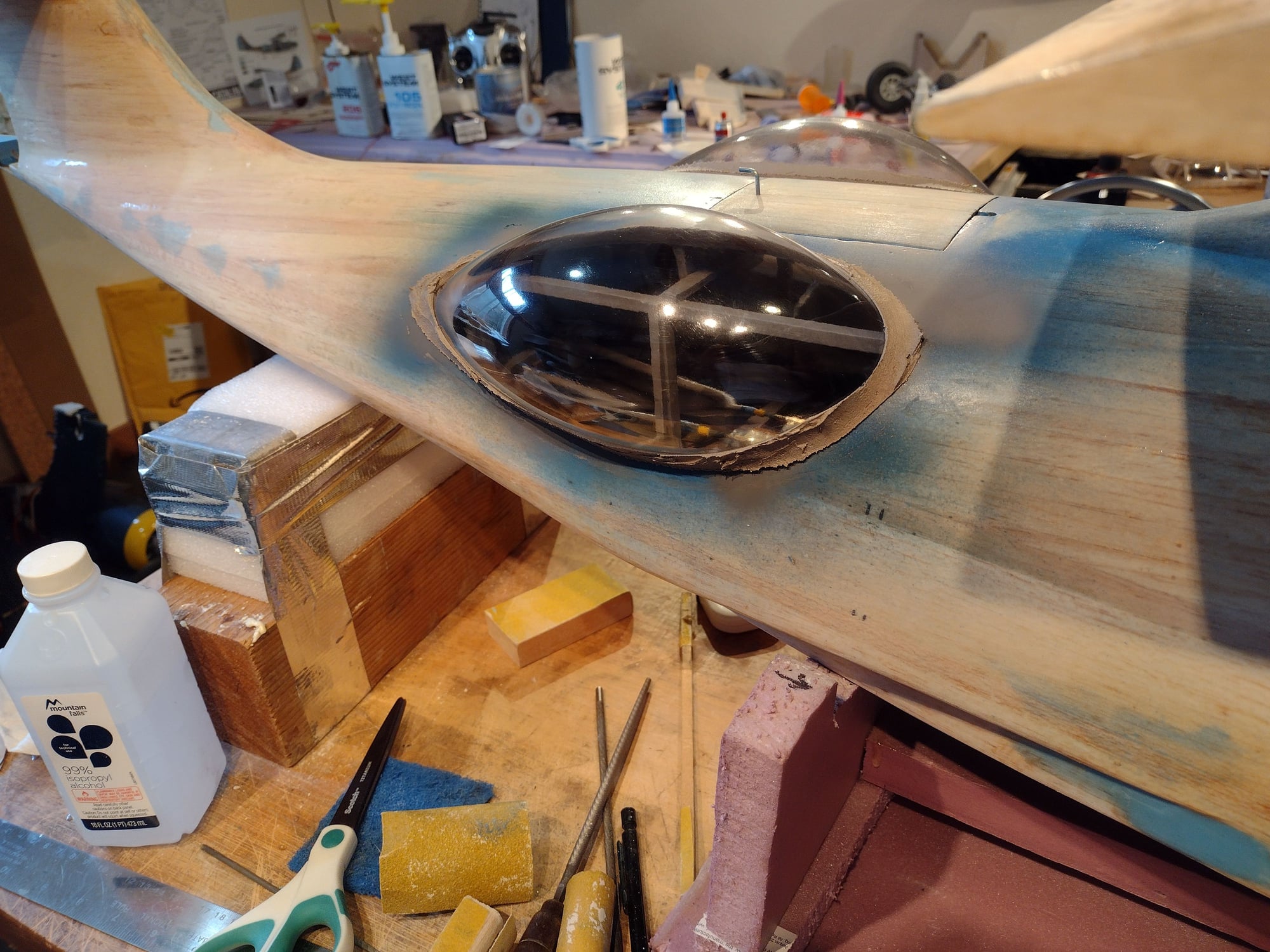
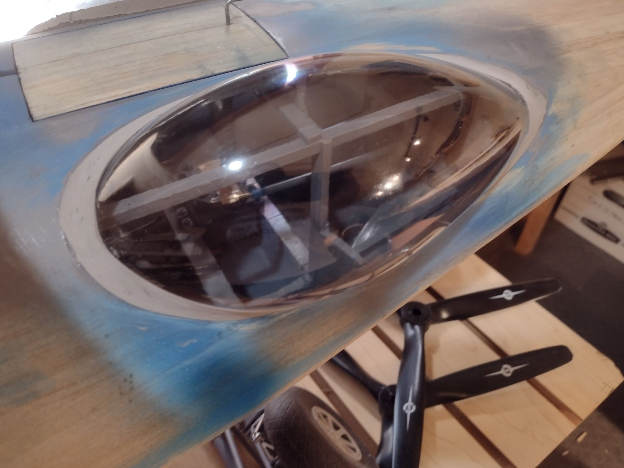
Senior Member
Finally time to put the side blister observation glass teardrops into place. Started by painting the inside grey. Then trimmed and tack glued the 2 teardrops in place. Then masked the teardrops. Applied an epoxy filler compound all around and sanded to the fuse.