


PBY Catalina (Vintage Plans) Build Thread

 03-02-2019, 03:13 PM
#52

Thread Starter
Join Date: Nov 2005
Location: fort collins,
CO
Posts: 448
Likes: 0
Received 0 Likes
on
0 Posts
With the tail mostly done, i'm moving on to the nose. I'll get the nose wheel gear doors working before any planking or other structure goes in, while it is still easy to access the inside of the nose.
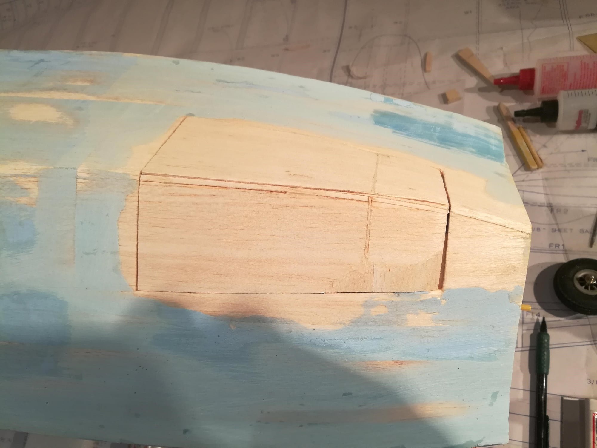
First thing is to get the doors ready. Taking the section of the hull that I cut out earlier, I cut it in half lengthwise to make to 2 doors. Given they're not glued to anything, they did not retain much of their bend and twist shape, so they don't fit nicely in the opening. First I added some supports in the opening to hold the doors. Then I added layers of balsa to the back side of the door. Finally, shape the now much thicker door to the shape of the fuse.
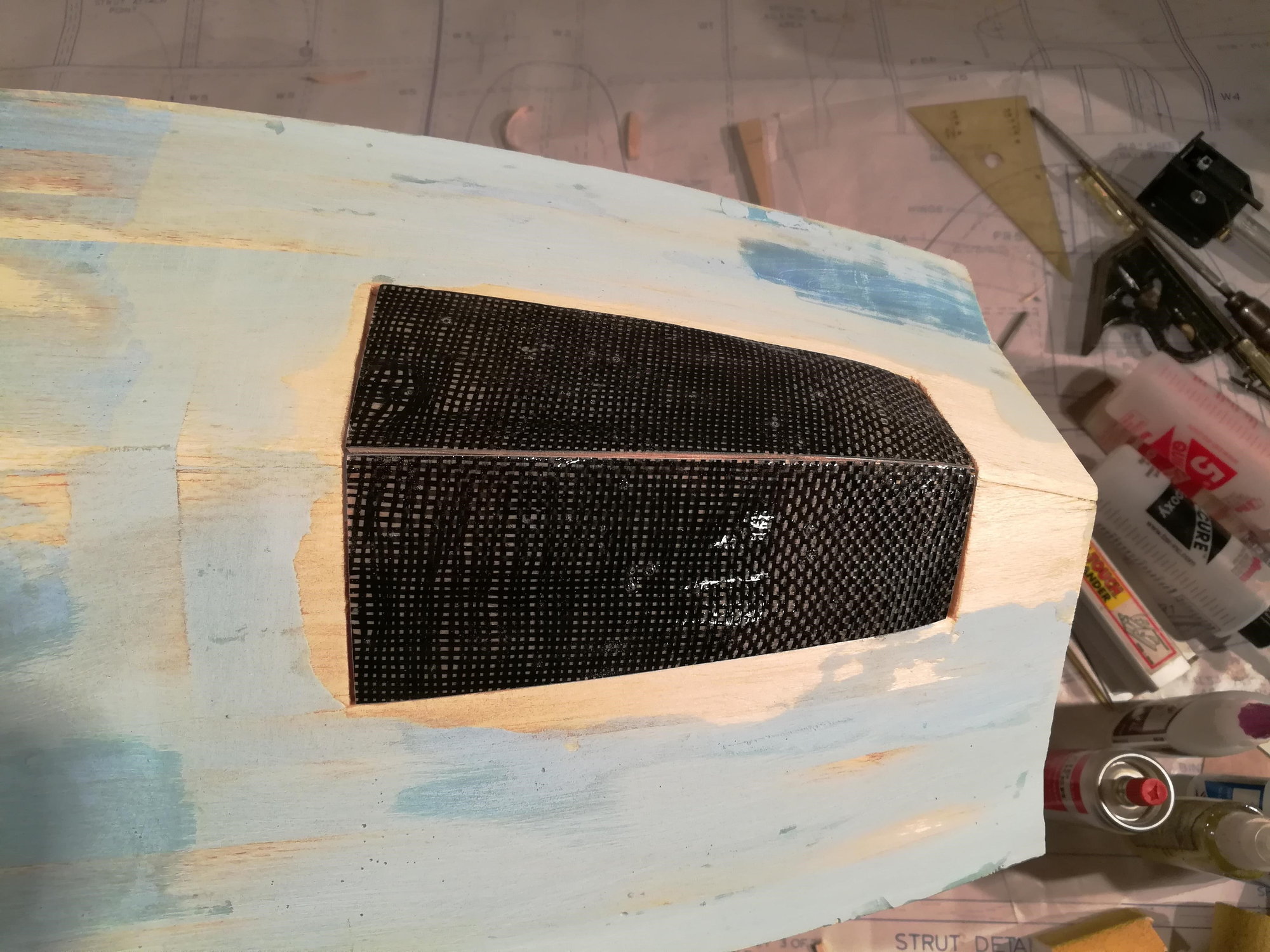
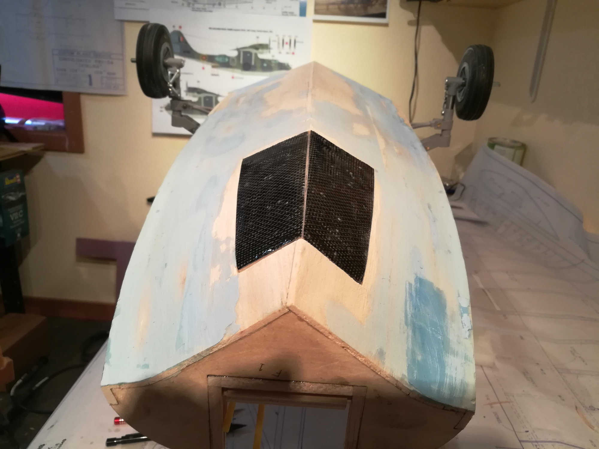
Now you need to get the doors to fit against each other along the center seam of the hull. Once I was completely satisified with the fit, I applied carbon fiber cloth to the outside of the doors. This will ensure that the doors keep their shape AND make the doors very strong against water landings. Later, the bottom of the hull will get the same treatment with carbon fiber.
Here's a few picts. In the first photo you can see the layers of balsa I added before shaping it. The door needs to be 3/8" think at the front.
First thing is to get the doors ready. Taking the section of the hull that I cut out earlier, I cut it in half lengthwise to make to 2 doors. Given they're not glued to anything, they did not retain much of their bend and twist shape, so they don't fit nicely in the opening. First I added some supports in the opening to hold the doors. Then I added layers of balsa to the back side of the door. Finally, shape the now much thicker door to the shape of the fuse.
Now you need to get the doors to fit against each other along the center seam of the hull. Once I was completely satisified with the fit, I applied carbon fiber cloth to the outside of the doors. This will ensure that the doors keep their shape AND make the doors very strong against water landings. Later, the bottom of the hull will get the same treatment with carbon fiber.
Here's a few picts. In the first photo you can see the layers of balsa I added before shaping it. The door needs to be 3/8" think at the front.
 03-03-2019, 09:06 AM
#54
Thread Starter
Join Date: Nov 2005
Location: fort collins,
CO
Posts: 448
Likes: 0
Received 0 Likes
on
0 Posts
The strength is for water operations. Both takeoff and landing pose a challenge to the doors and hull. On a takeoff run at 20mph the doors will be getting hammered. Especially if she skips on the run (i.e. becomes airborne momentarily and touches the water again). Even during the run, water will stream all around the doors, pulling on them. Landings will pose issues too. The doors again will come in contact with the water at high speed, even if you make a nose high touchdown. And we all don't make perfect landings

Also from my friend Bill (who supplied the landing gear) has a lot of experience with waterborne models having designed at least a half dozen. His experience shows that over time the doors take a pounding and need to be set up to survive.
As for the hull needing strengthening, it's only 1/8" balsa to start. Full scale PBYs on hard landings could pop rivets and split seams. While the forces aren't exactly the same, we only have thin balsa here. I normally finish balsa surfaces with 0.75oz fiberglass before paint. While this makes a light and smooth finish for paint, it adds little material added strength. Instead, 2oz carbon fiber will make the bottom of the hull tougher then aluminum. 2oz fiberglass would work just as well. I use carbon fiber fabric to increase the load carrying capability of many key parts (like the rudder as I mentioned earlier). Here it is superior to fiberglass. I have it available, so will use it on the hull.
Kind of a long answer, but I hope this helps.
03-03-2019, 04:51 PM
#55

Let me chime in on this one.
While CF is stronger than FG, it can still be very brittle and can crack or, worse still, break along the grain. If you lay it down with the CF grain running lengthwise, it will not add that much more strength since the balsa has it's grain running the same way.I would recommend a second layer, laid at a 45* angle to the first, along the bottom where the hull will take the most abuse. With a plane this size, a second layer won't add enough weight to be an issue but it might prevent a grain wise break in the hull.
While CF is stronger than FG, it can still be very brittle and can crack or, worse still, break along the grain. If you lay it down with the CF grain running lengthwise, it will not add that much more strength since the balsa has it's grain running the same way.I would recommend a second layer, laid at a 45* angle to the first, along the bottom where the hull will take the most abuse. With a plane this size, a second layer won't add enough weight to be an issue but it might prevent a grain wise break in the hull.
03-16-2019, 02:12 PM
#57
Thread Starter
Join Date: Nov 2005
Location: fort collins,
CO
Posts: 448
Likes: 0
Received 0 Likes
on
0 Posts
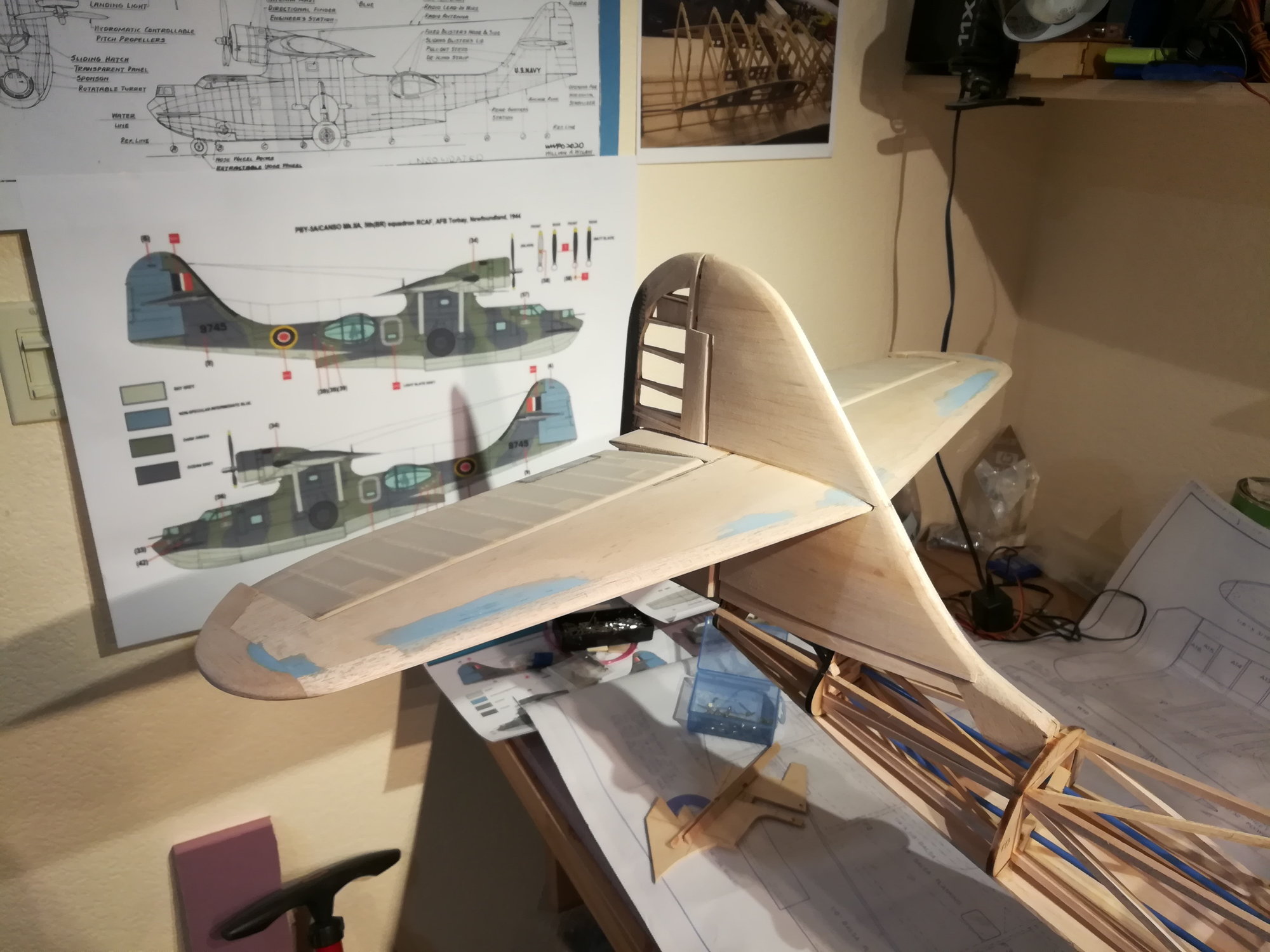
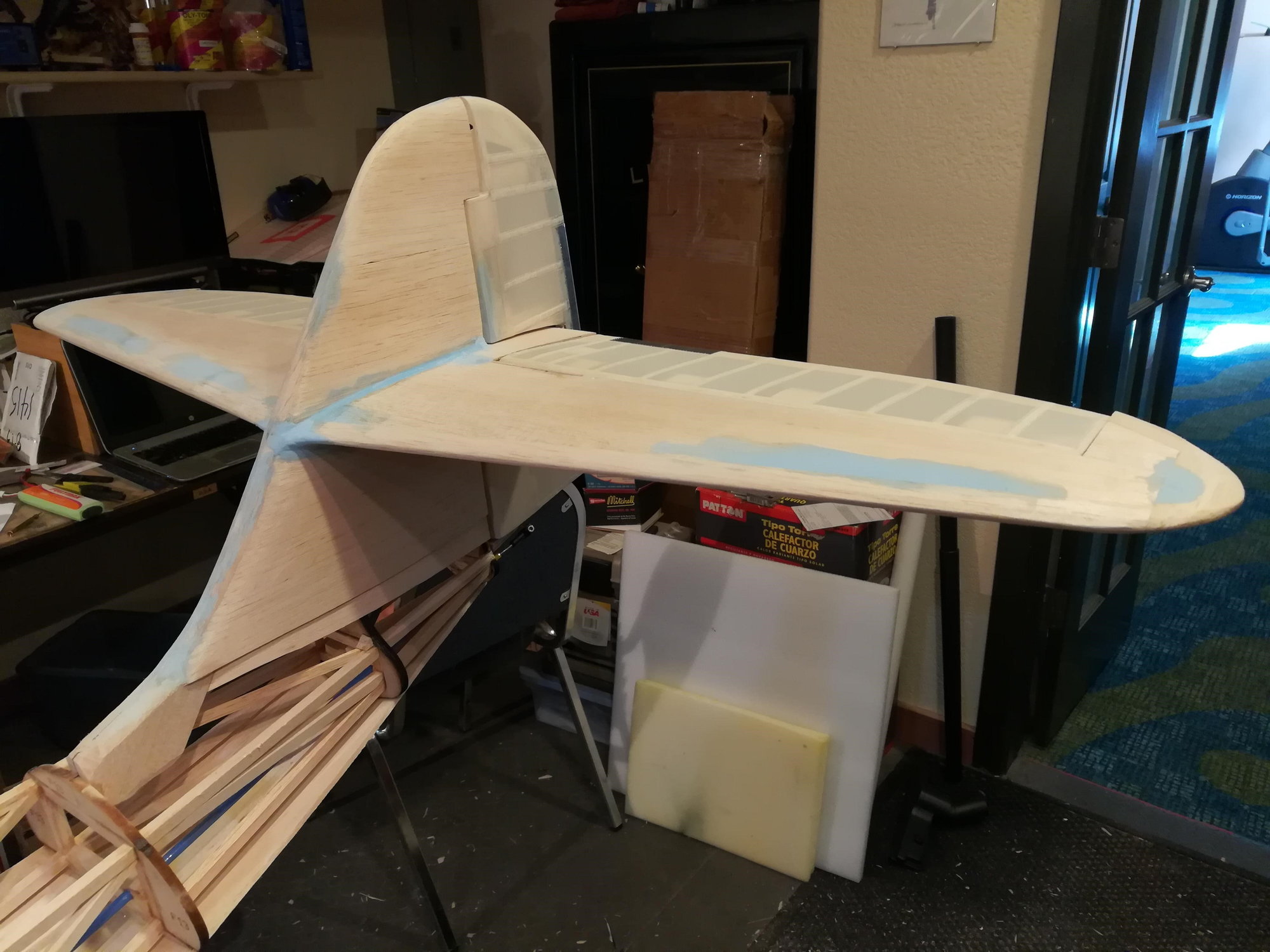
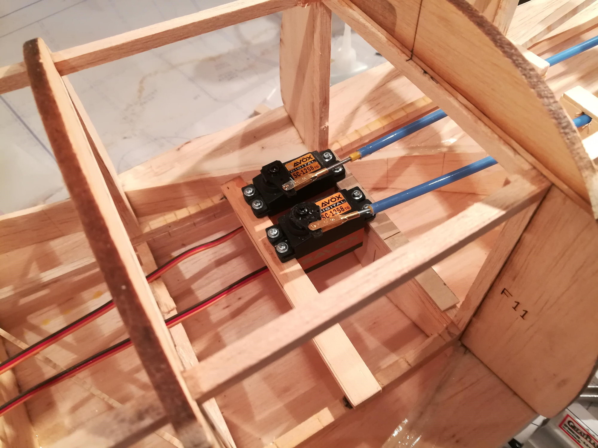
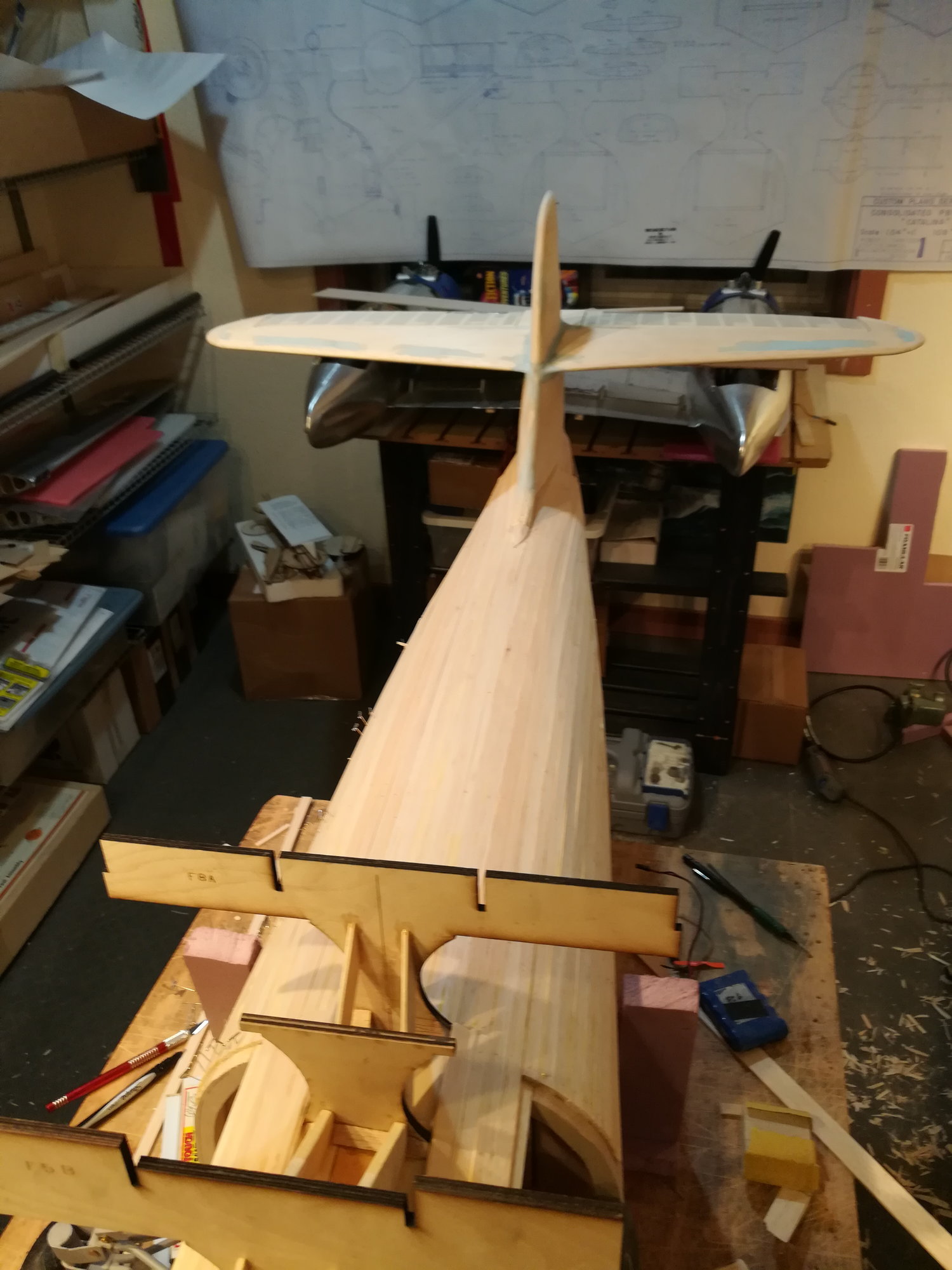
Wrapping up this phase of the tail. Surfaces covered. Stitching complete. Basic sanding complete. Elevator and Rudder servos mounted. Regarding the servos, I had hoped to fit everything under the cockpit hatch. But there really won't be enough room. So I will make one of the waist blisters into a hatch. This allowed me to keep the ele/rud pushrod runs short and the extra hatch will give me access to the back side of the main gear retracts.
03-26-2019, 07:03 PM
#58
Thread Starter
Join Date: Nov 2005
Location: fort collins,
CO
Posts: 448
Likes: 0
Received 0 Likes
on
0 Posts
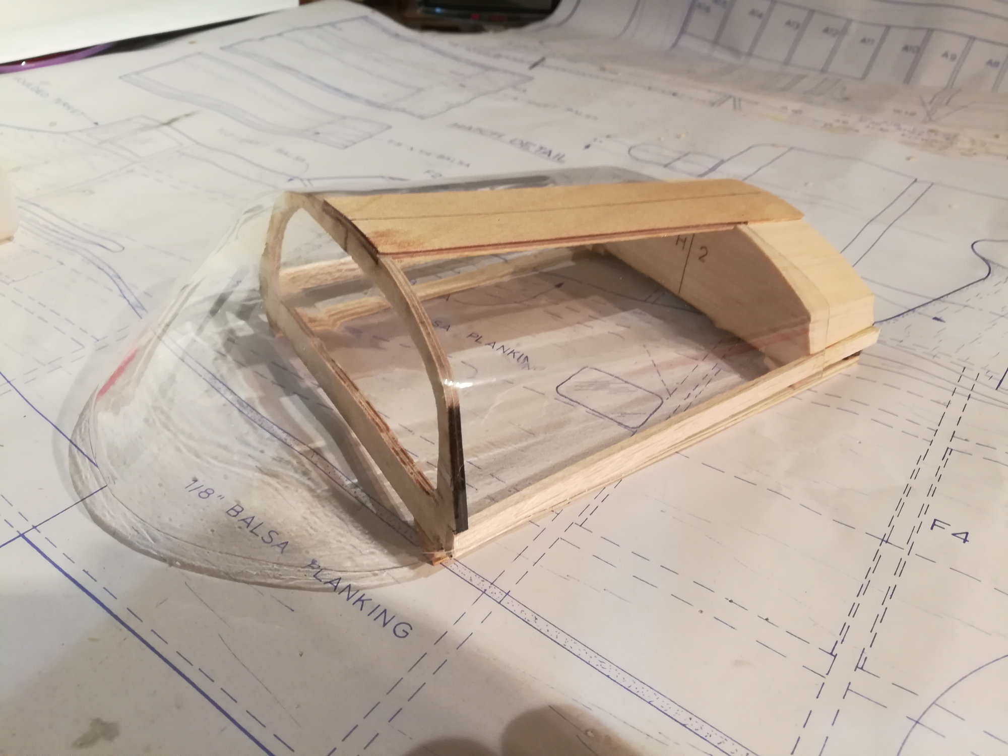
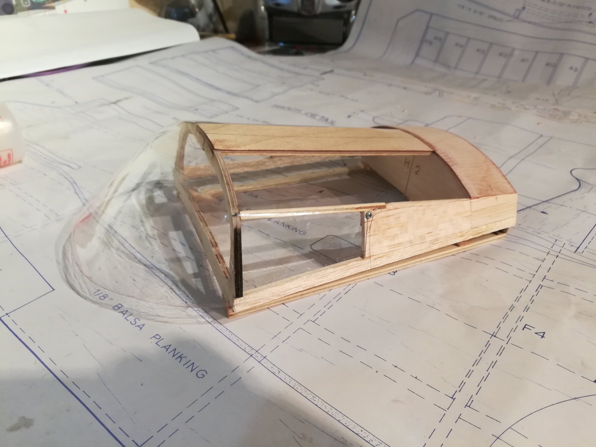
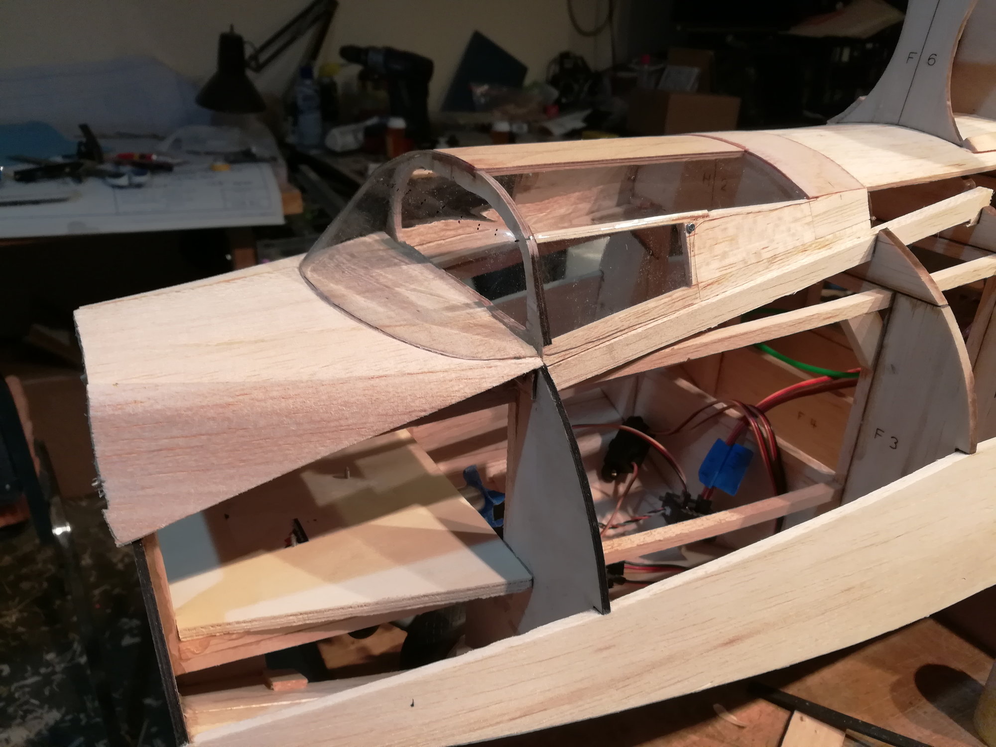
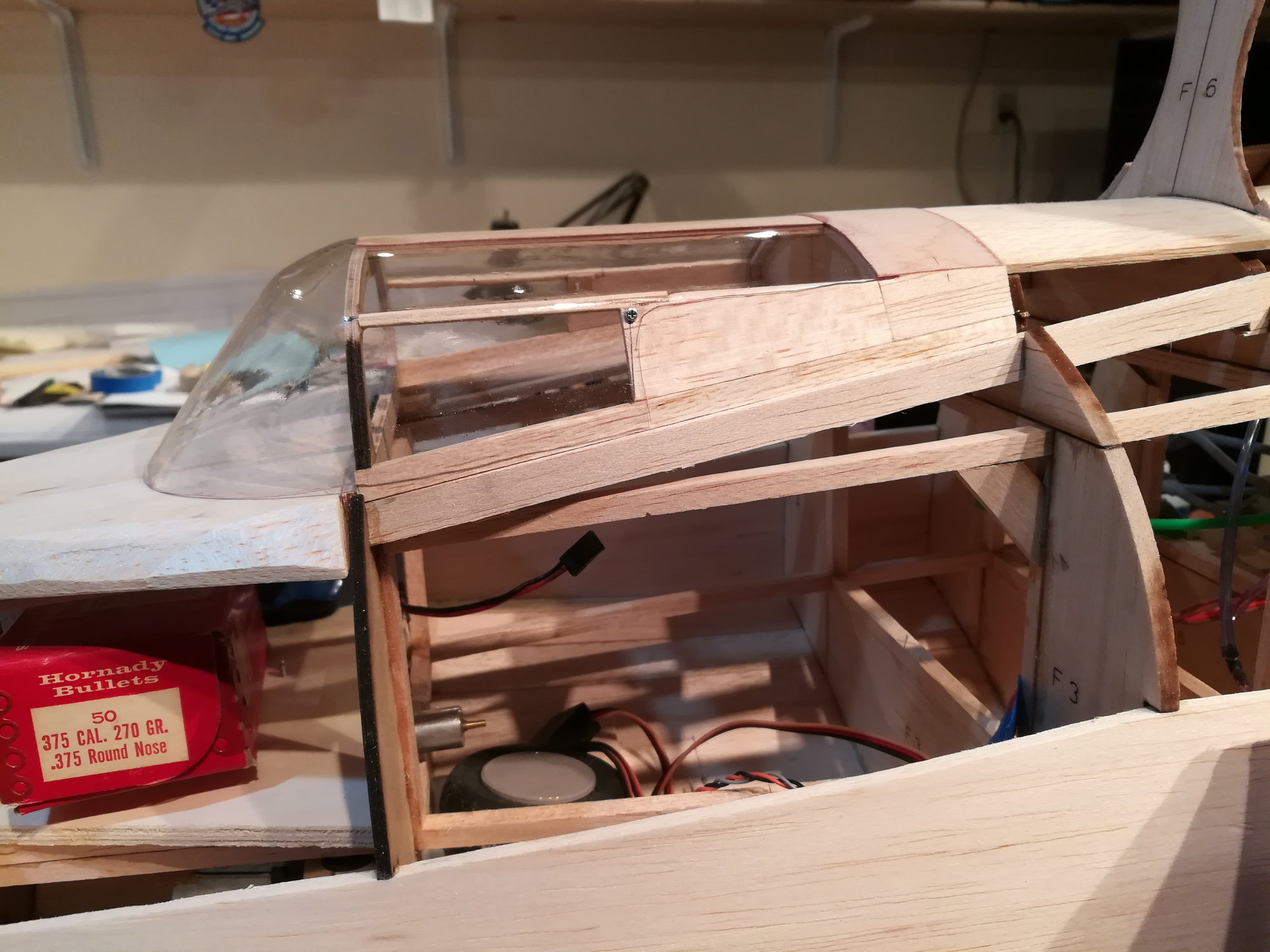
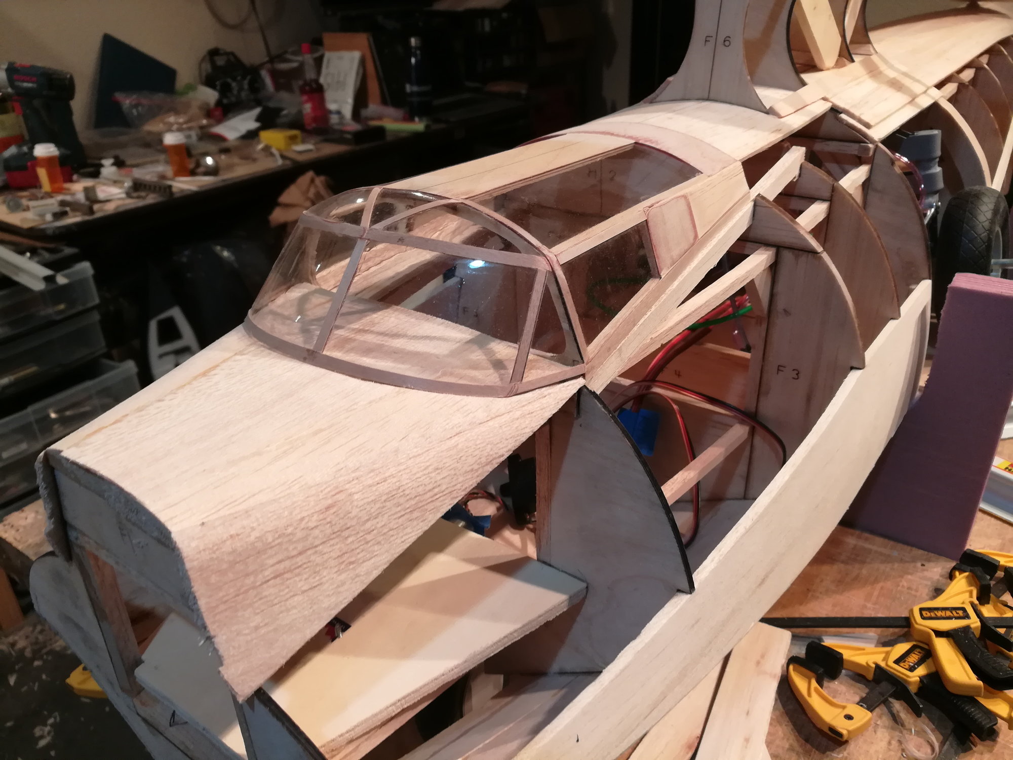
The canopy is the typical vacuum formed deal. If you look at the drawings of the plan you'll see that the fuse structure is really interleaved with the canopy. I could just paint the parts that represent where the fuse is vs. glass. But, I really want all this structure to pop out, as it represents a lot of cool detail. So, here's the insanity of doing the complete canopy structure!
03-26-2019, 07:06 PM
#59
Thread Starter
Join Date: Nov 2005
Location: fort collins,
CO
Posts: 448
Likes: 0
Received 0 Likes
on
0 Posts
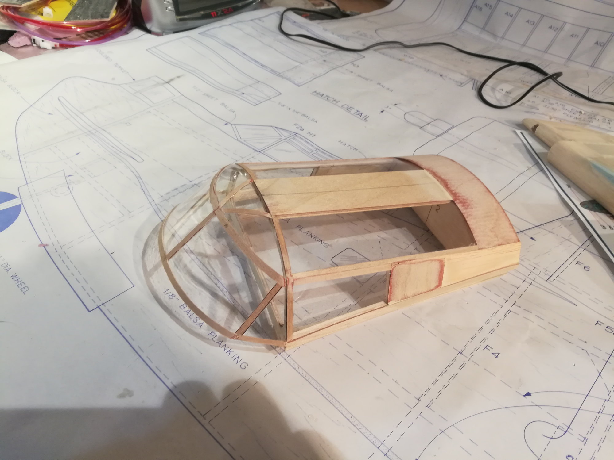
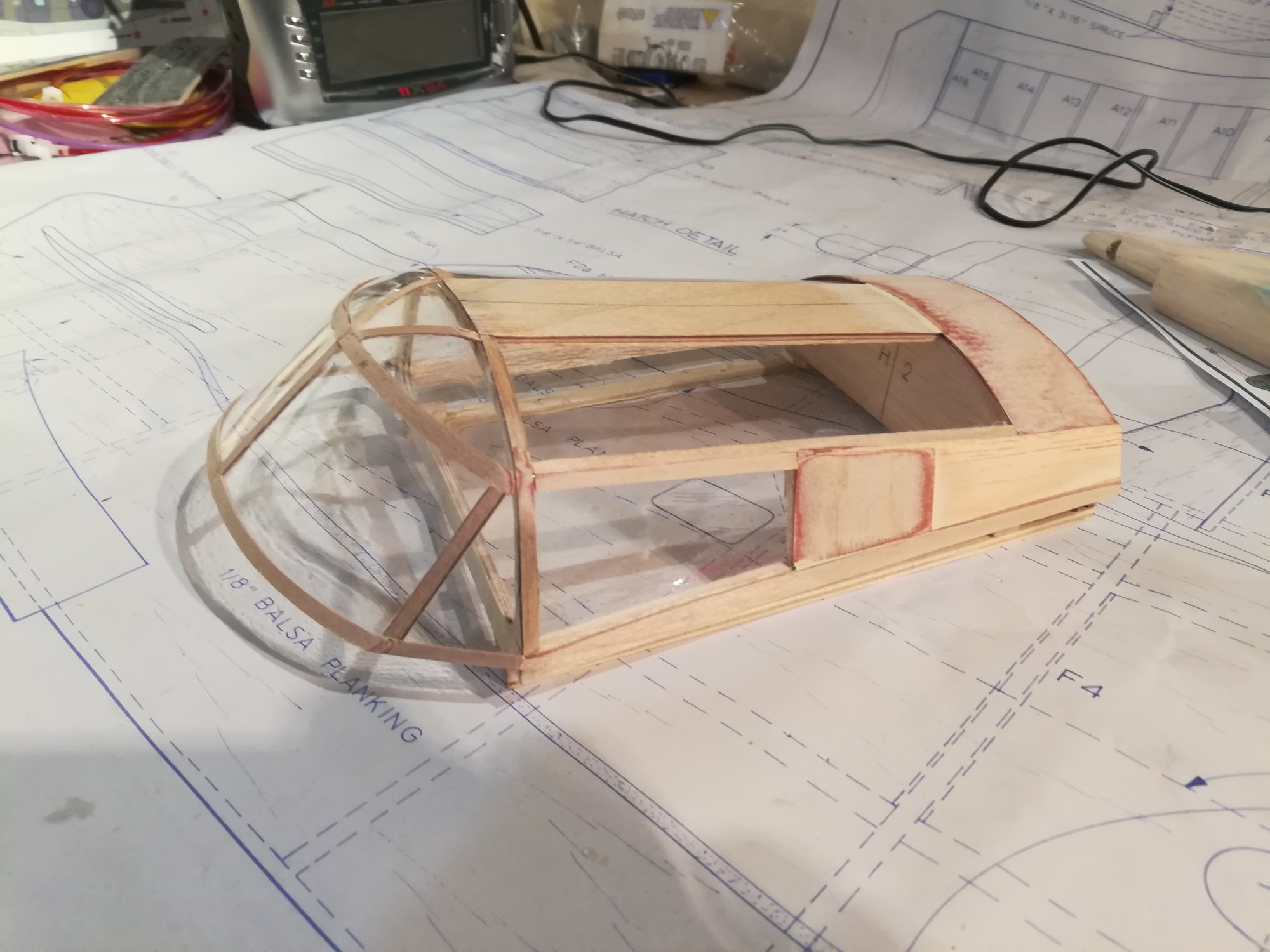
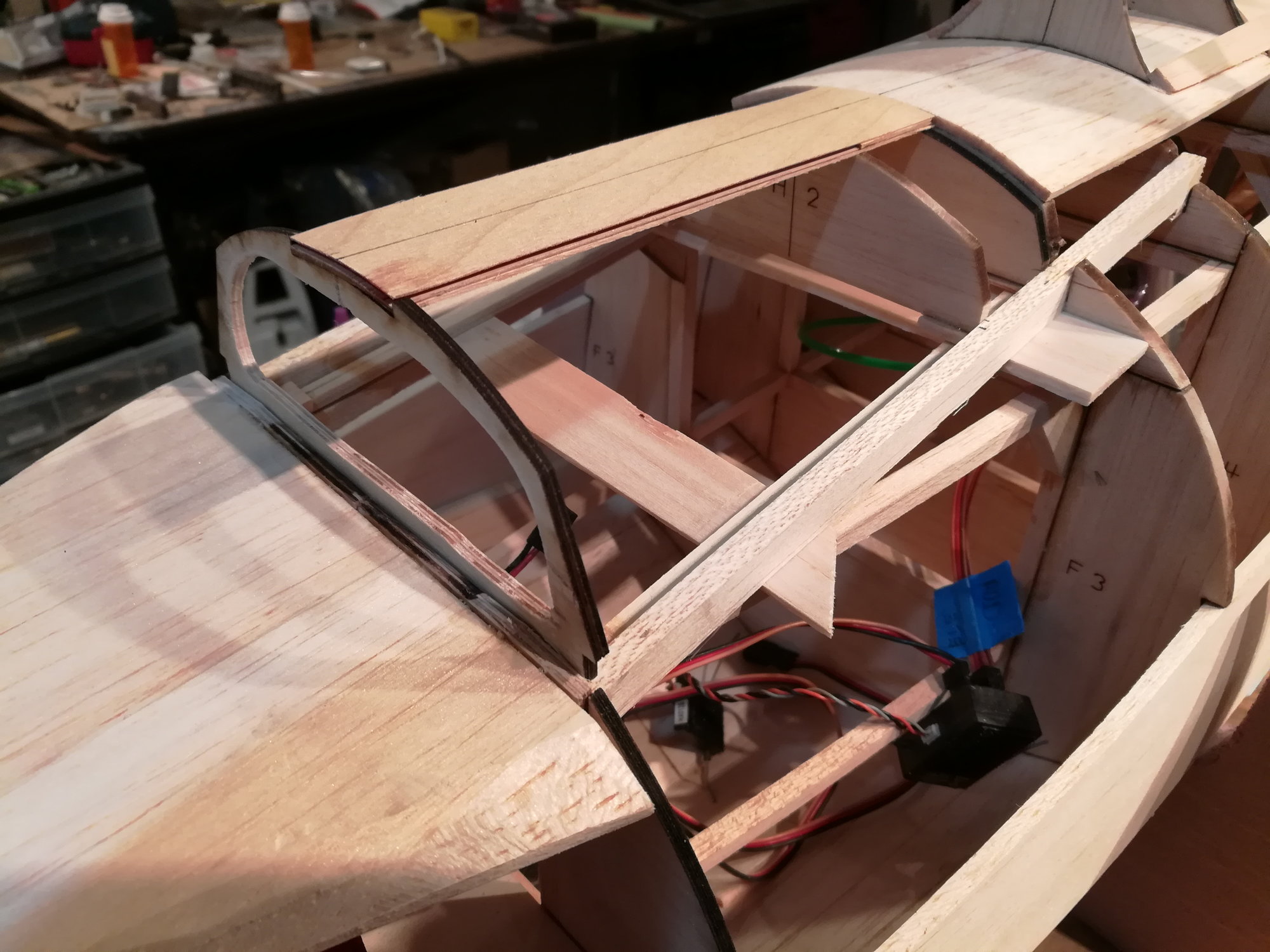
Here's the progress of fitting it to the fuse. LOTS of sanding and tweaking to get it right!
Last edited by Eldher; 03-26-2019 at 07:09 PM. Reason: added a photo
 04-27-2019, 10:49 AM
#62
Thread Starter
Join Date: Nov 2005
Location: fort collins,
CO
Posts: 448
Likes: 0
Received 0 Likes
on
0 Posts
It's been a while since I posted ... been getting some flying in 
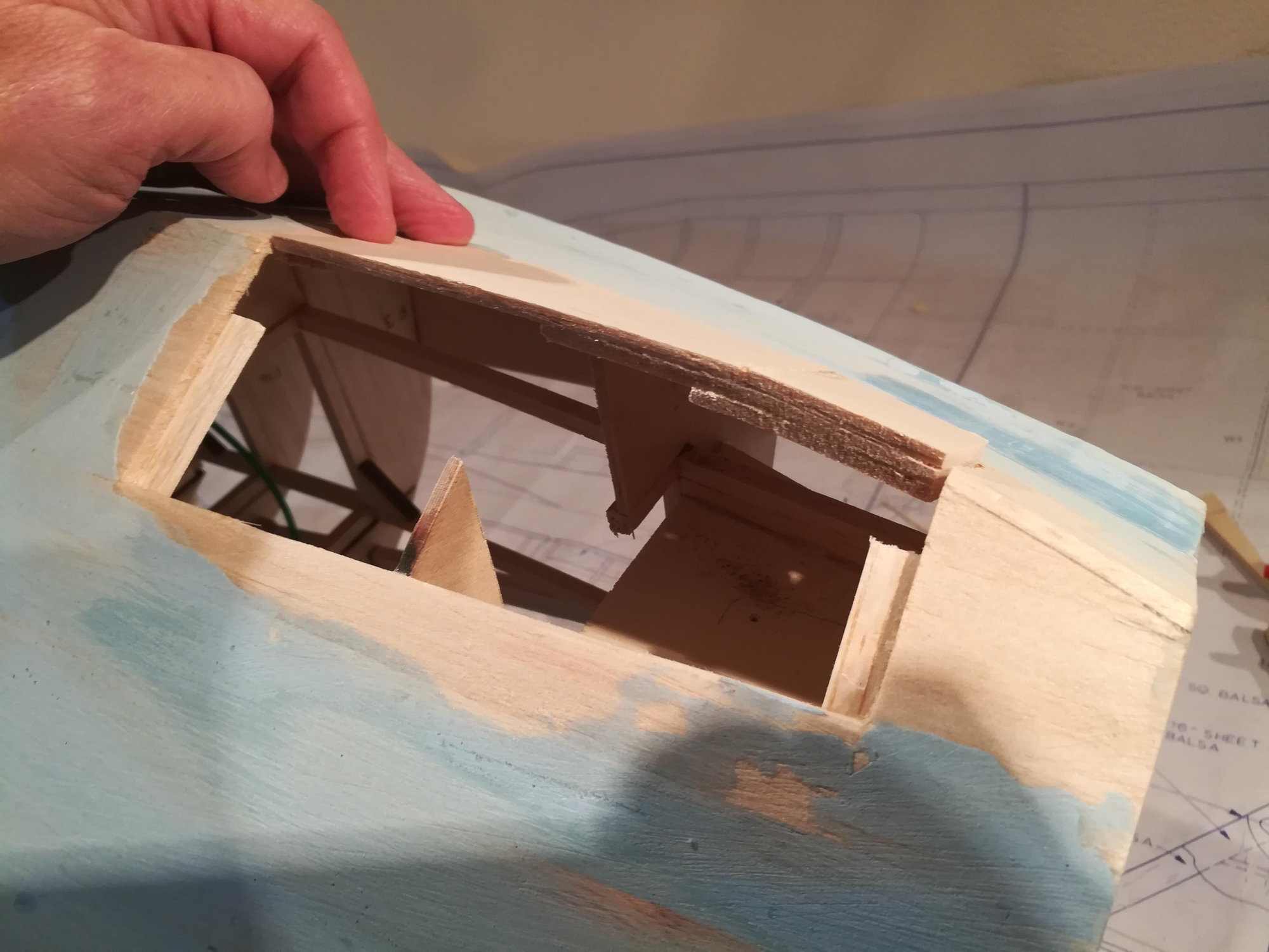
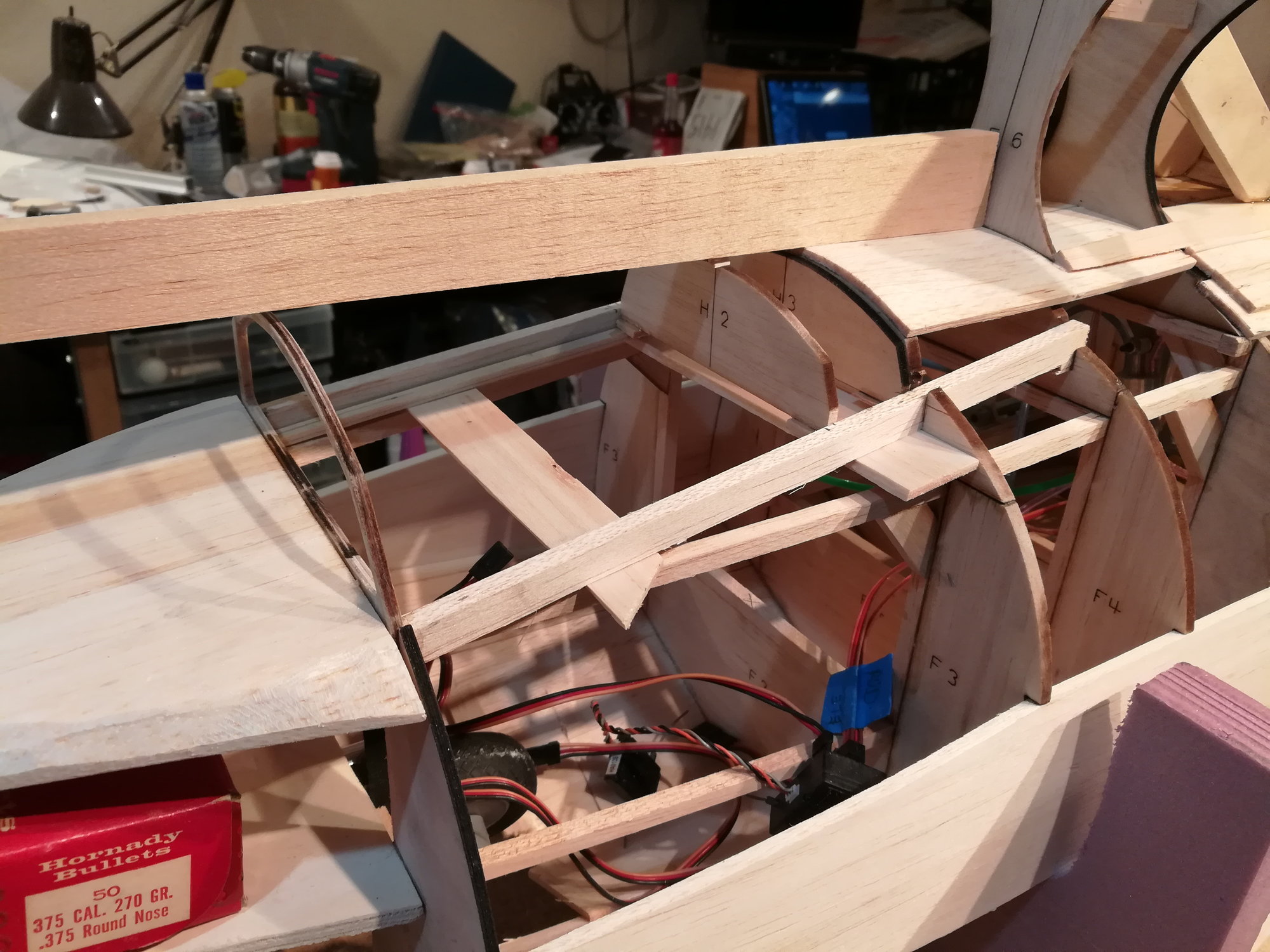
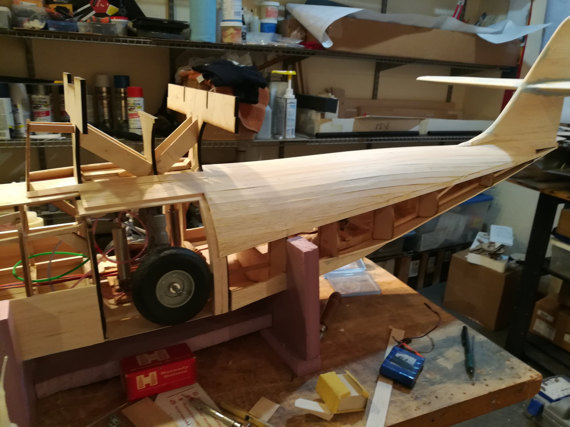
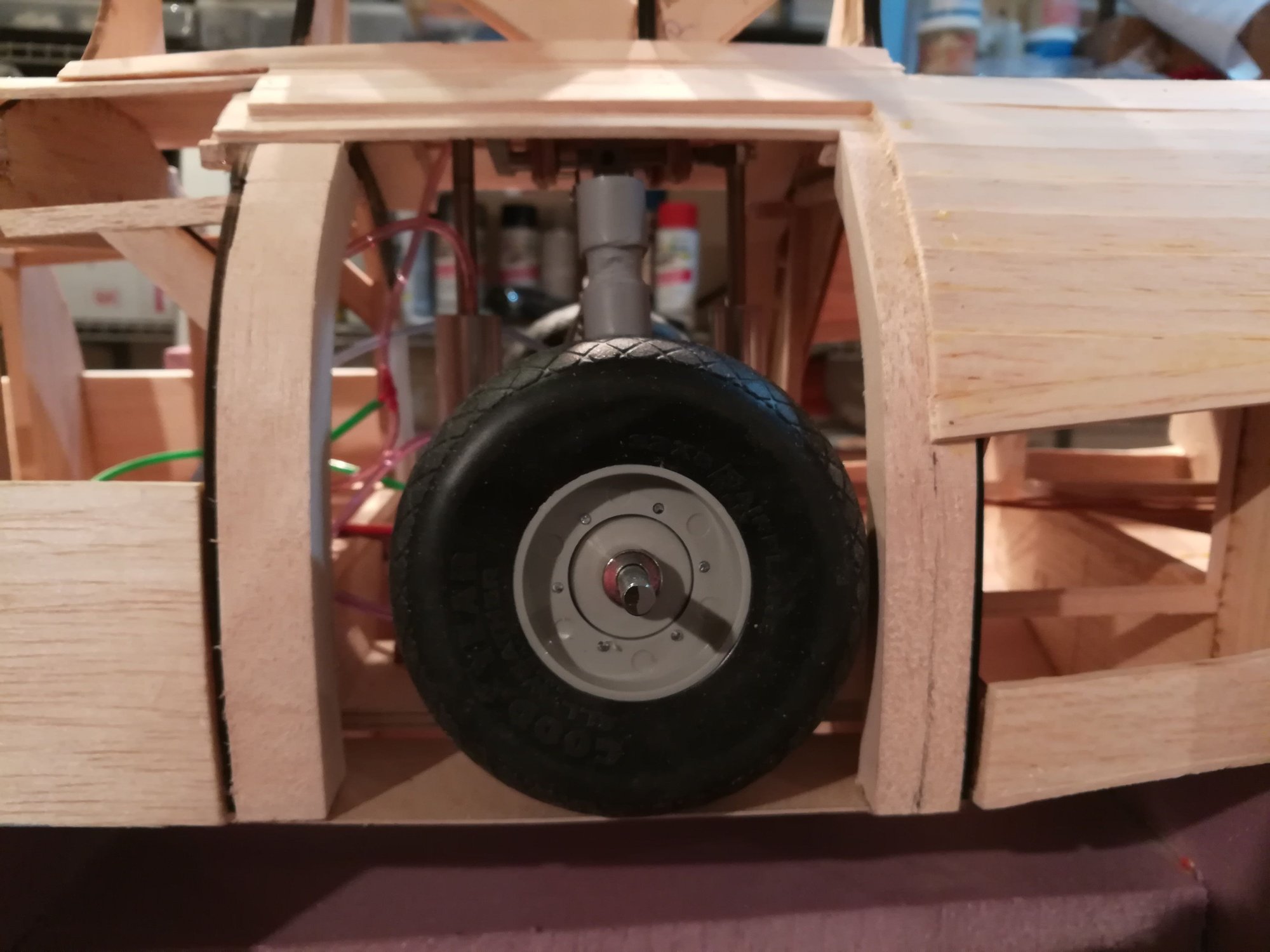
But there's been some progress on the plane too. I have started to fill in the area between F5 and F8 where the landing gear are. With nothing to follow in the plans, I have been making it up as I go. I started by adding 1/2" wide balsa formers to the inside edges of F5 and F8. These will support the planking when it goes on and give me enough wood to work with to cut a removable section out later. The removable section will start about 1.5" above the water line and go to the bottom of the pylon. This will provide access to maintain the retract system. Here's some picts of the work so far.
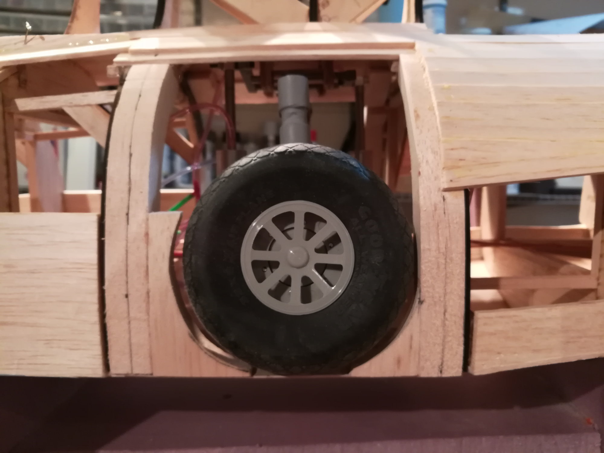
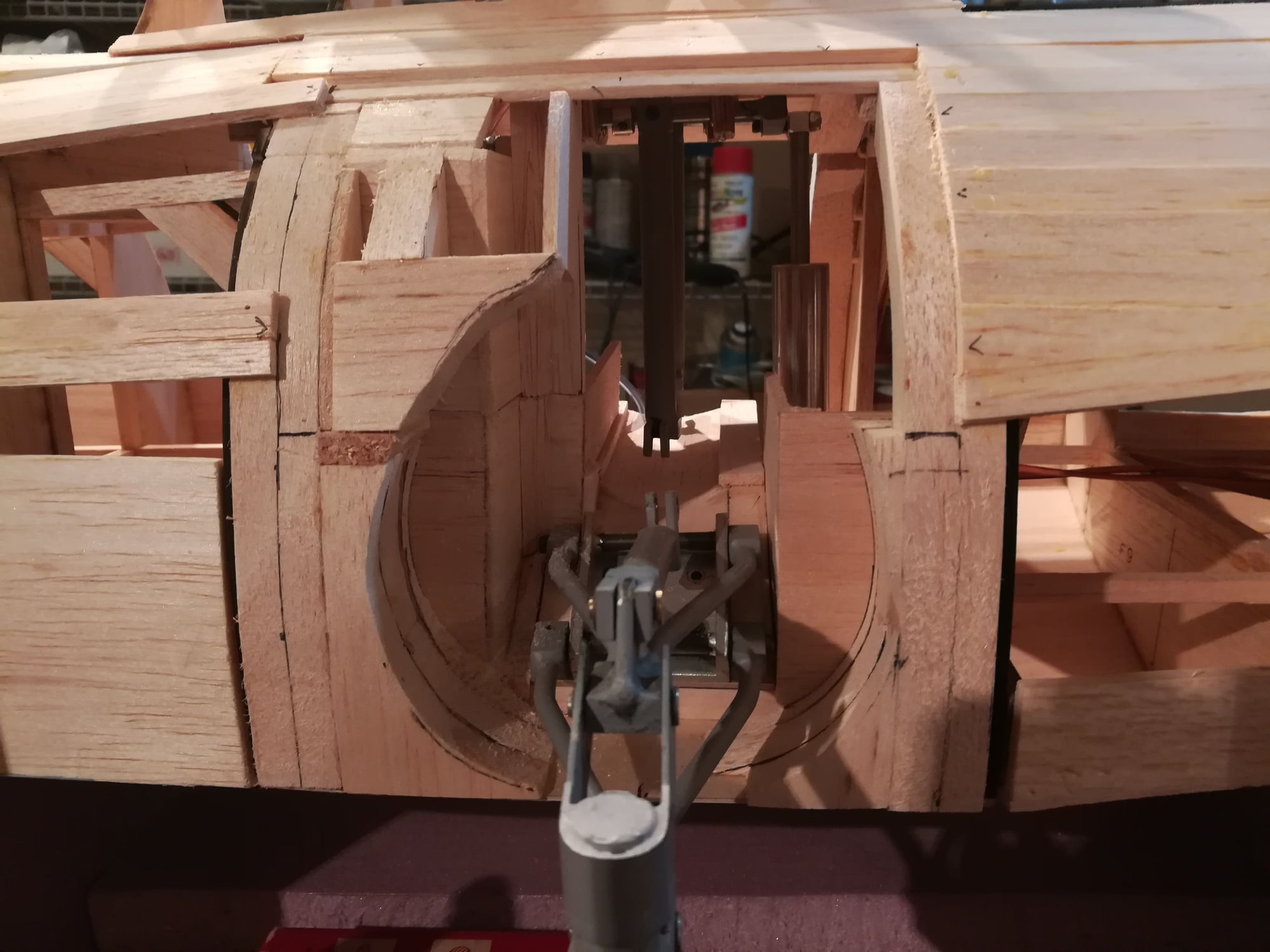
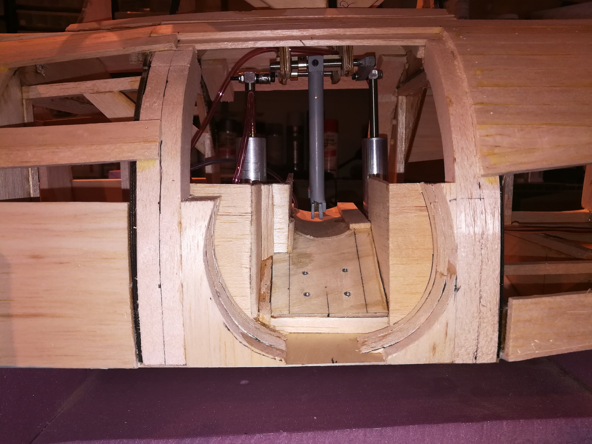
But there's been some progress on the plane too. I have started to fill in the area between F5 and F8 where the landing gear are. With nothing to follow in the plans, I have been making it up as I go. I started by adding 1/2" wide balsa formers to the inside edges of F5 and F8. These will support the planking when it goes on and give me enough wood to work with to cut a removable section out later. The removable section will start about 1.5" above the water line and go to the bottom of the pylon. This will provide access to maintain the retract system. Here's some picts of the work so far.
09-23-2019, 01:58 PM
#63
Junior Member
Join Date: Sep 2019
Location: Newfoundland, Canada
Posts: 6
Likes: 0
Received 0 Likes
on
0 Posts
Nice build. I really like the retracts. Are you going to make the wing tip floats retract too?
I built a PBY5A about 28 years ago. I believe it was the 84" version. It's still home in the attic complete with hanger rash.
She was hard to get up on her step but flew beautifully when you got her out of the water. Always planned to build another with twin OS/Grapnel Rotary Wankel's in it. I have the engines just need the time and the right size plans.It'll happen some day!
Keep up the good work, looking forward to seeing the end product!
02-02-2020, 11:08 AM
#64
Senior Member
Hey out there, to anyone still tracking this thread, this is Eldher. RCU "lost" my login info as I can't get a reset password. So, I am back now and starting to work on the Catalina again.
Jdolomount - yes, the wing tip floats will retract. Absolutely!
I've finished closing up the wheel well area and continued the planking. Will post picts soon.
Jdolomount - yes, the wing tip floats will retract. Absolutely!
I've finished closing up the wheel well area and continued the planking. Will post picts soon.
 02-02-2020, 12:08 PM
#69

Join Date: Nov 2002
Location: Taylor,
MI
Posts: 21
Likes: 0
Received 0 Likes
on
0 Posts
02-03-2020, 08:24 PM
#71
Senior Member
My plane has a 108" wing span, about 1/12th scale. I will be using a pair of Saito FG-21 (1.26 ci). The plan was not designed for retracts. I had to extensively modify the mid section of the fuse and the pylon to accommodate the retracts from a space and loading perspective. You can look at the early posts here to see the mods.
02-03-2020, 08:27 PM
#73
Senior Member
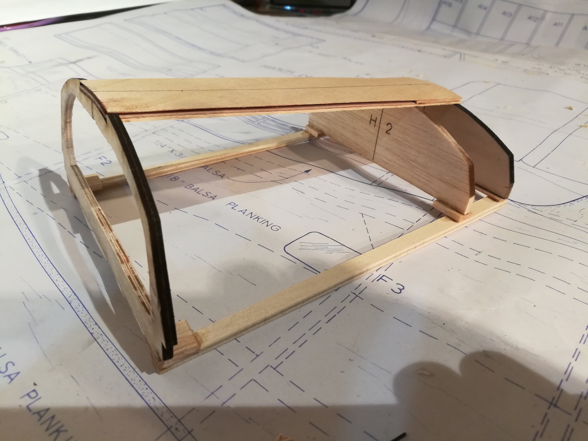
Headed for that magic 10 posts :-) ... now i am working on the nose section. the forward most 4" is made of a solid balsa block (per the plans). But I want some guide for the shape. I cut a profile of the nose from 1/8" ply and added balsa blocks to either side to get to the rough shape.
02-03-2020, 08:31 PM
#74
Senior Member
Before I started shaping the blocks, I put in another piece of ply. This one is in the place of the bombardier's window in the nose. With these 2 references, I was able to start shaping. Using a dremel tool with a coarse sanding drum. I set up my shop vac hose on the table and just let it run while grinding away balsa.
02-03-2020, 08:32 PM
#75
Senior Member
The 3 views I have don't help much in shaping the nose. Just too complex a shape. I like to have a plastic model of the actual plane to help me visualize the complex 3D parts of the plane.