


Custome 1-Off 1/24 Losi Trophy truck
 03-15-2018, 09:16 AM
#26

Thread Starter
Join Date: Feb 2007
Location: Toronto,
ON, CANADA
Posts: 279
Likes: 0
Received 0 Likes
on
0 Posts
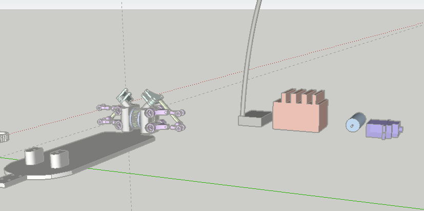
Well I finally got my esc and motor in, good job HK, only took 1.5 months lol.
The esc is A LOT bigger than I expected. I forgot how big stuff is I guess after working with micro scale for so long.
Probably going to have to re design the chassis a bit so I can get everything as low and center as possible.
As of right now everything is on the upper chassis brace just for testing. It all works, and the esc programmed up no problem. Happy with everything as of right now.
Maybe ill get to it this weekend, schools super busy so Im not sure I can afford the time to do other things.
We will see.
 03-15-2018, 07:47 PM
#27
Thread Starter
Join Date: Feb 2007
Location: Toronto,
ON, CANADA
Posts: 279
Likes: 0
Received 0 Likes
on
0 Posts
Threw together a short video of it running in the basement. Not the greatest production value, but it gives you an idea of it running.
https://www.youtube.com/watch?v=BBw9...ature=youtu.be
https://www.youtube.com/watch?v=BBw9...ature=youtu.be
03-27-2018, 09:23 PM
#28
Thread Starter
Join Date: Feb 2007
Location: Toronto,
ON, CANADA
Posts: 279
Likes: 0
Received 0 Likes
on
0 Posts
Well Dr. Frankenstein has been at it again..
Hes what I've got to show you guys.
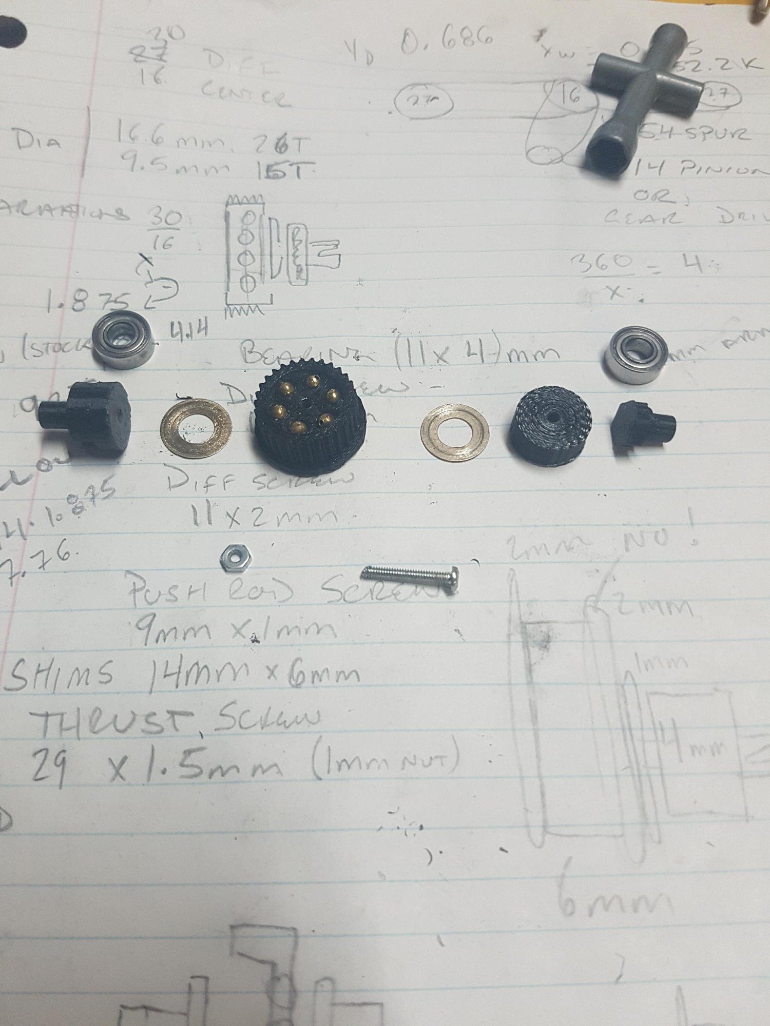
The diff gear is 30T which is very comparable to whats currently out there (Atomic Belted 1/27th uses 27T). Took a while to get the calculations right, but the meshing is perfect with my 2MM pitch belt.
Im using brass 3mm bb's in the ball diff, and the left and right plate will be sandwiched against the balls by the bearings. Im really hoping I can get enough pressure without having to have a screw go through the whole diff, like more traditional 1/10th scales.


Hes what I've got to show you guys.
The diff gear is 30T which is very comparable to whats currently out there (Atomic Belted 1/27th uses 27T). Took a while to get the calculations right, but the meshing is perfect with my 2MM pitch belt.
Im using brass 3mm bb's in the ball diff, and the left and right plate will be sandwiched against the balls by the bearings. Im really hoping I can get enough pressure without having to have a screw go through the whole diff, like more traditional 1/10th scales.
03-28-2018, 07:13 PM
#29
Thread Starter
Join Date: Feb 2007
Location: Toronto,
ON, CANADA
Posts: 279
Likes: 0
Received 0 Likes
on
0 Posts
So Im trying this new approach, Design a million times, print once ahah, to avoid the 8 prototype chassis, 2 sets of rims multiple top braces ordeal that I had previously.
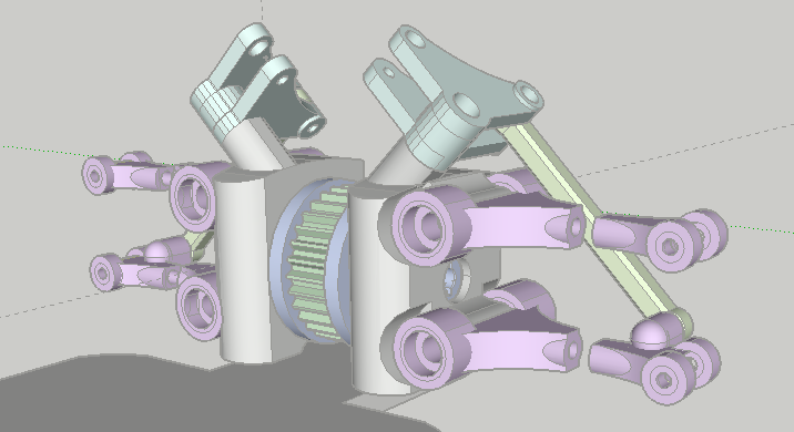
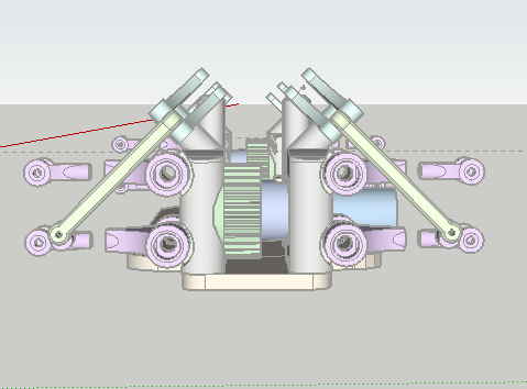
Decided to make my own a-arms for two reasons:
1. adjustable camber (stance nation obv)..
2. Ball diff is wider than stock diff by ~3 mm's so adjustable length arms will keep my track width the same, but allow for the bigger diff.
Still not 100% sure on the ball diff design. Its very common that the belt sits on left or right side of the diff housing, to allow for the center pulley to accommodate both belts ie, rear belt on left, front belt on right.
So I will most likely be changing that, I also think I'm going to need a tightening screw in my diff, Im skeptical about the pressure being enough.
Anyway here is what I have so far..
03-30-2018, 10:03 PM
#30
Thread Starter
Join Date: Feb 2007
Location: Toronto,
ON, CANADA
Posts: 279
Likes: 0
Received 0 Likes
on
0 Posts
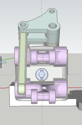
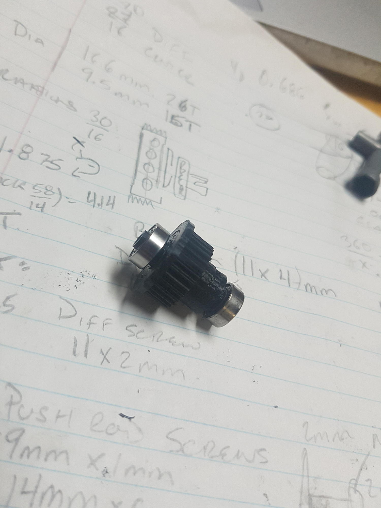
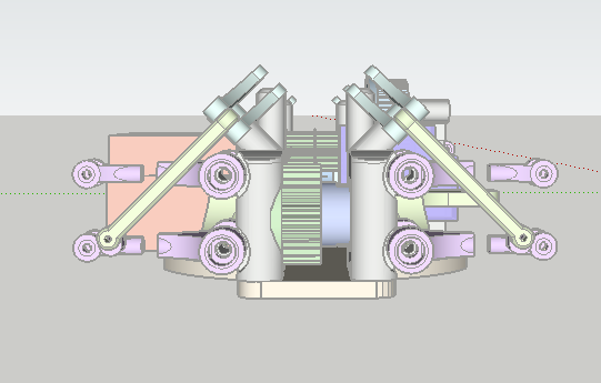
Alrighty, so here is what I have done so far.
Ball Diff is complete. Lets hope it stands up to some power.
A LOT of ingenuity on my end had to go into designing it so that it works the way it should as well as dealing with working on such a small scale.
It is now secured with a nut and bolt, might swap over to a nylon locking nut for something more rugged.
Got my gear ratios worked out so now I am turning my attention to the center pulley and the spur gear (completely belt driven).
This will get done tomorrow hopefully than maybe sunday (fingers crossed) I can have it running. Thats a very optimistic fingers crossed though..
03-31-2018, 09:32 PM
#31
Thread Starter
Join Date: Feb 2007
Location: Toronto,
ON, CANADA
Posts: 279
Likes: 0
Received 0 Likes
on
0 Posts
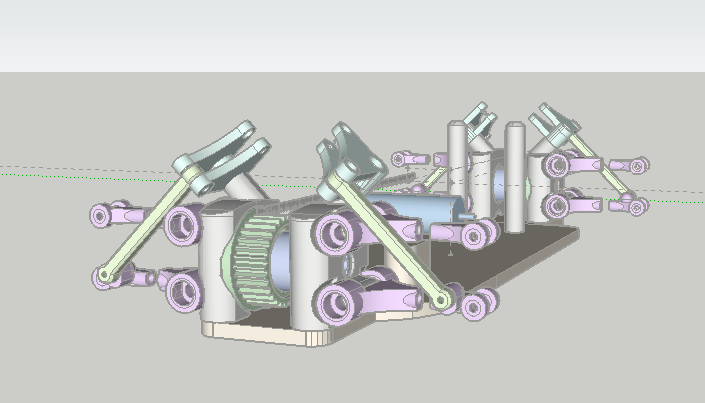
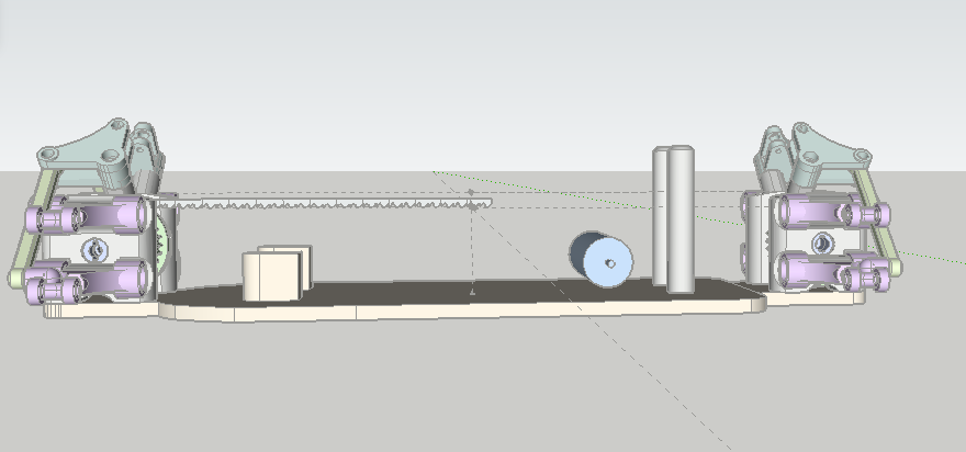
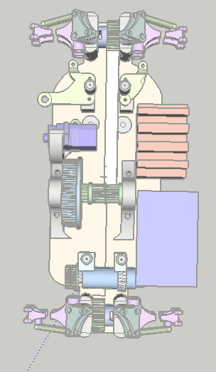
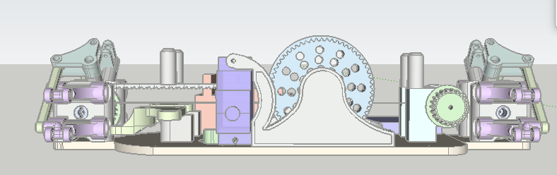
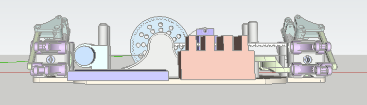
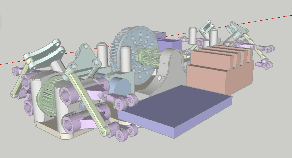
Well today was productive. Managed to get most of the chassis designed and everything arranged.
Only thing remaining is to mount the receiver above the bell crank, and to design the front shock mounts, and add in belt tensioners. Should be ready to start printing tomorrow!
The diffs are ball bearings, the center pulley and spur are on bushings. Shouldn't really hinder performance I recon.
Only thing remaining is to mount the receiver above the bell crank, and to design the front shock mounts, and add in belt tensioners. Should be ready to start printing tomorrow!
The diffs are ball bearings, the center pulley and spur are on bushings. Shouldn't really hinder performance I recon.
04-03-2018, 09:10 PM
#32
Thread Starter
Join Date: Feb 2007
Location: Toronto,
ON, CANADA
Posts: 279
Likes: 0
Received 0 Likes
on
0 Posts
Well got the chassis printed out. You can see that there is some issues with the mounting of the diff housing on the chassis. I will have to move the mounting holes out by 1mm or so. It's probably an error on my part, 3d sketches always fit better on a computer. Not too bad for a first print though. I really am enjoying the black on purple. Might not be for everyone, but I think it makes it pop. Spur gear is printed, thing took 2 hours! But it's perfect. Centre shaft is nice and tight, and the bushings fit perfectly. Also pictured is the front Bell crank.


