I molded up some light covers (lenses) last night and took some pics of the process hoping that this might answer some questions as to how to make custom formed lenses.
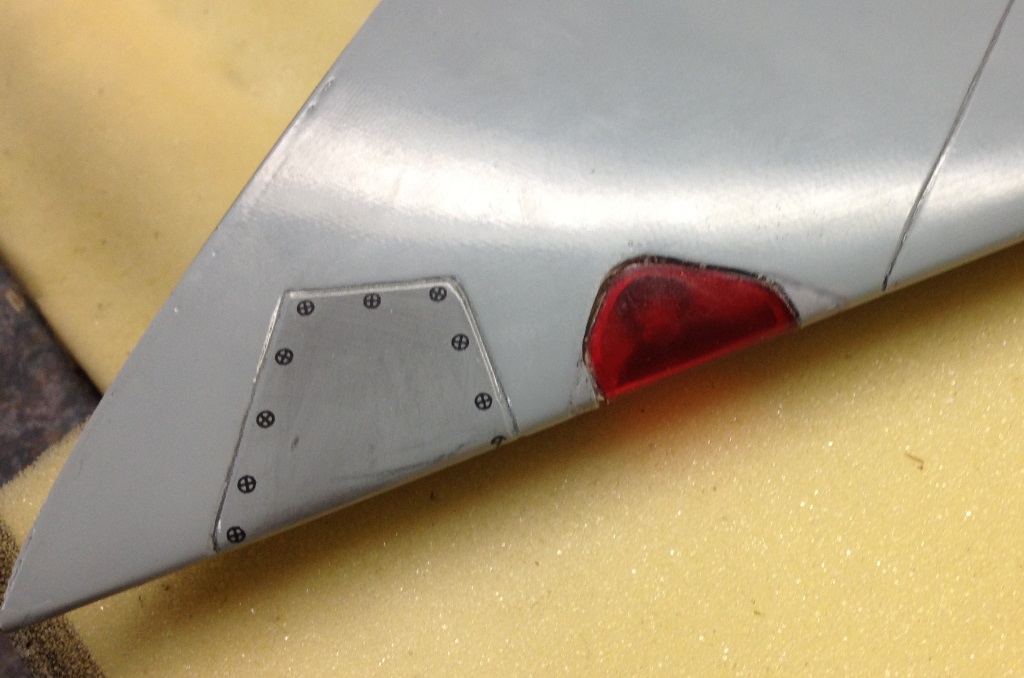
These lenses are for the navigation lights on a BVM Rafale and are located near the root chord of the wing. The tight bend radius at the leading edge posed a bit of a problem as did finding a way to attach the covers. The wingskins are a composite of carbon fibre, with a balsa core, and a layer of fiberglass on the exterior. They are about 1/16" thick. After making the cutout in the wing, I used a small file to file away the CF inner skin around the hole until the skin thickness was about .040 (the approximate thickness of the lexan sheet I bought at my local hobby shop). Then I glued a piece of .005" thick polyply to the inside skin and then ground the polyply away the make a 1/16" wide flange around the cutout to which the light cover will be glued.
Pieces of lite-ply were sanded to shape and glued into the wing to line the cutout and to hold the light. The ply was sealed with primer then painted white to better reflect the light. A hole was ground into the lite-ply to mount the light (from Electrodymanics - see
http://www.electrodynam.com/store/SunVis.html) which was CA'd in placed.
The light cover (lens) itself was formed by heating a 2" x 2" square of Lexan. It seemed like too much work to splash a female mold of the leading edge of the wing so I just sanded a piece of balsa to the approximate shape for a male plug. I "sealed" the plug to prevent the balsa grain from leaving impressions on the Lexan by taping a sheet of paper over the plug. The Lexan was held with a pair of pliers and heated with a heat gun until it was very soft and would flap in the stream of air from the heat gun. Then it was QUICKLY draped over the plug. Another piece of paper and a piece of a file folder were QUICKLY placed over the Lexan and I manually formed the Lexan over the plug.
The formed Lexan was offered up to the wing and a fine tip Sharpie marker was used to trace the rough outline of the cutout. A Dremel was used to grind away the excess material. This is a bit of a grind/check/grind iterative process so take your time or you might grind away too much and have to start over.
After the lens was a good fit, I masked the outside of the lens and sprayed the inside with Tamiya translucent spray paint. It took two coats to get the right paint thickness/coverage. The lens was then glued to the polyply flange using canopy glue (flexible, clear, and will allow the lens to be removed in the future if necessary). Some putty will be used to fill the slight gap around the lens and aluminum tape circles will be added to the lens to simlate the fasteners used to hold the lens in place on the full scale aircraft.
Regards
Jim