Speed Brake
The speed brake was an item I was keen to incorporate into this jet and Xtreme have included a well proportioned brake and supplied it pre-fitted with aluminium hinges.
I would have preferred to either have hinges not fitted or hinges that you could remove the pins from so that the brake could be removed to work on fitting the linkage. Hopefully the latter will be done on later kits.
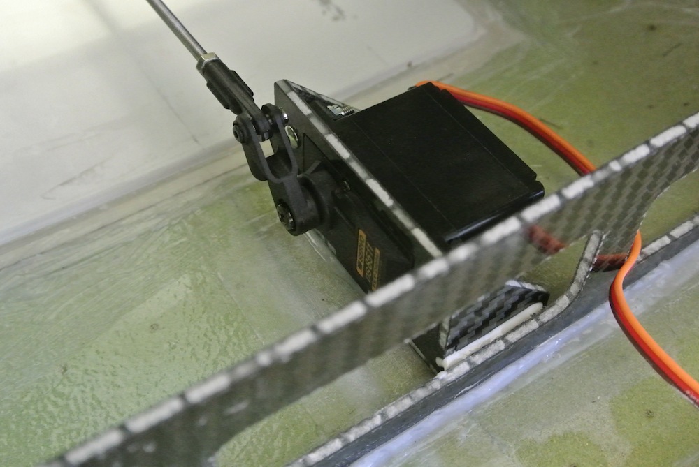
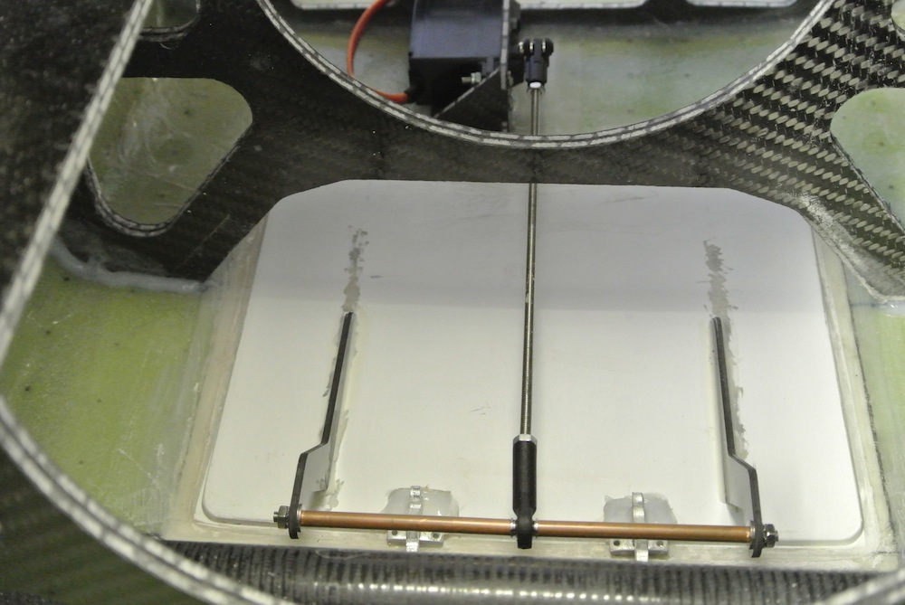
When Rich built the first prototype he arranged the speed brake servo forward of the actual brake in front of the rear wing tube former, this location resulted in the servo location being off centre as the former has a central strengthening post, as a result and due to my weird desire to keep things symmetrical I have opted to locate the servo behind the brake so it can remain central. Hopefully it wont cause any issues operating the brake located here.
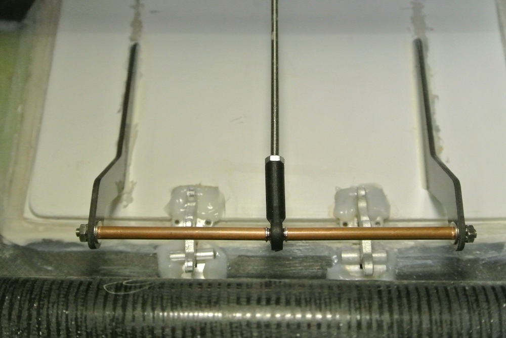
With hinges fitted all that is required to do is fit the horns, these are supplied as two cnc cut carbon fibre items which have long base legs to extend mid way down the brake to give a good area to fix the horns to. I guess you can fit them close together like a 'double' horn in between the hinges, I opted to spread them outboard of the hinges and make up a simple linkage bar from some 3mm threaded rod and copper tube slipped over at each end to locate the ball link at the mid-point.
Marked up the brake, keyed the area where the horn base legs were located positioning the linkage over the hinge point. Scuffed the horns, tacked them in place with cyano and microballons and then filleted with Hysol.
There is a servo tray supplied which comes in 4 parts, made from the same carbon sandwich material used in the formers of the Vixen, it assembles easily and after keying and cleaning with acetone I glued with cyan and microballons. The JR8511 fitted exactly without modification.
Sorted the threaded M3 rod linkage and ball link to give the right length and keyed the servo mount and fuselage base. Glued servo mount to fuselage with Hysol.