Indexing the stab control horn to the stab
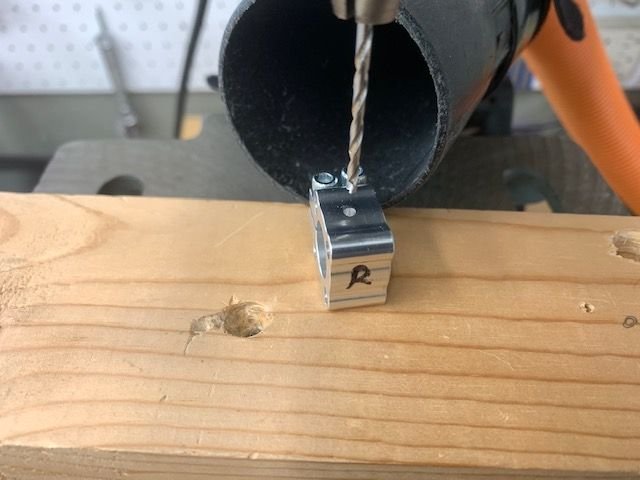
First step was drill a 6-32 tap pilot hole in the inside clamp block to accept the indexing set screw
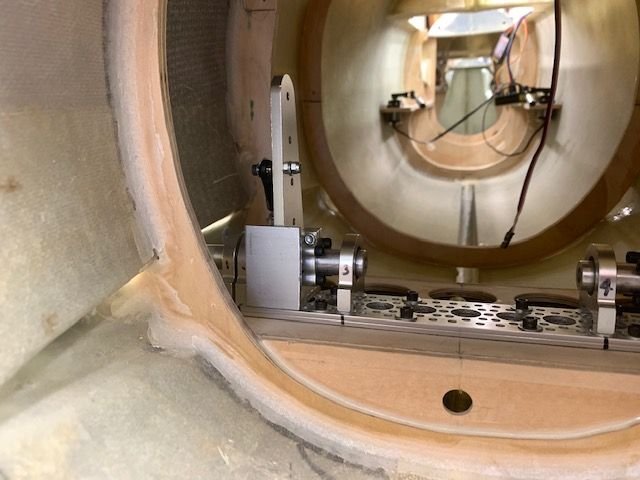
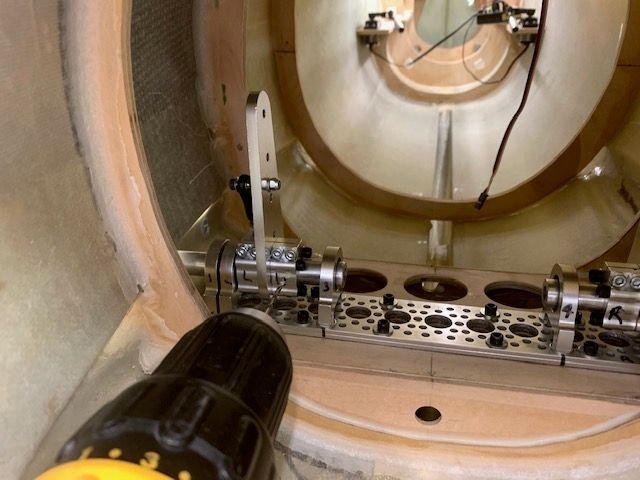
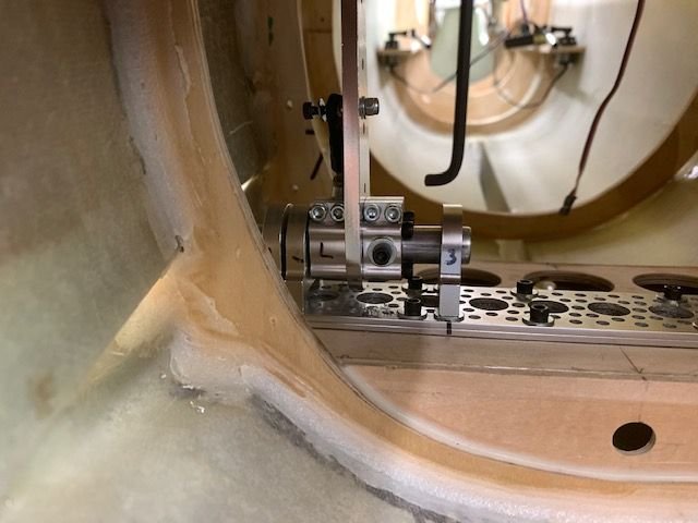
Next was to assemble the stab and horn. I use the molded stab farings on the fuse to establish the stab alignment with the fuse. I have no idea if this is anywhere near where the stabs should be for level flight but it is a place to start and looks the same on both sides.
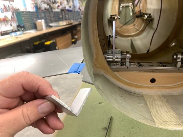
Next was aligning the horns with the base plate. I used a cut off of aluminum angle to align the rear edges of the horns. They are not exactly vertical due to the tapered shape but close enough. At least they are the same on both sides.
Right side done
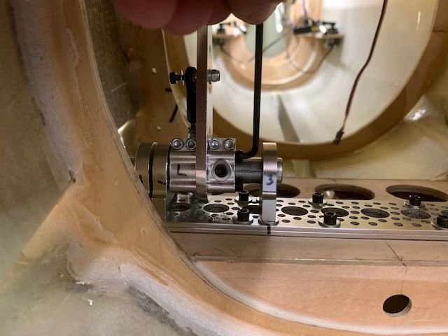
Next the clamp screws were tightened and the 6-32 tap pilot hole was drilled into the stab tube rear edge
Next the holes were tapped for a 6-32 set screw.
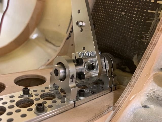
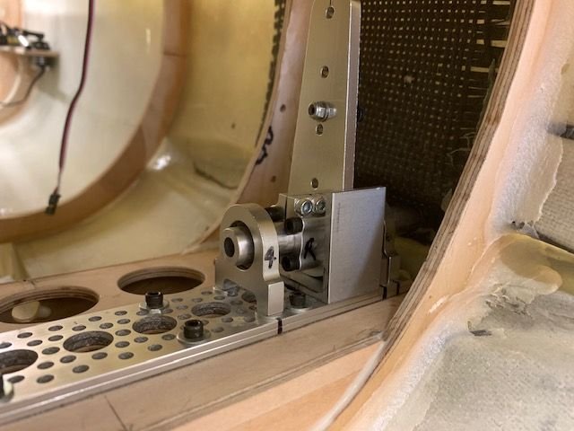
Set screw installed with flat washer and lock washer.
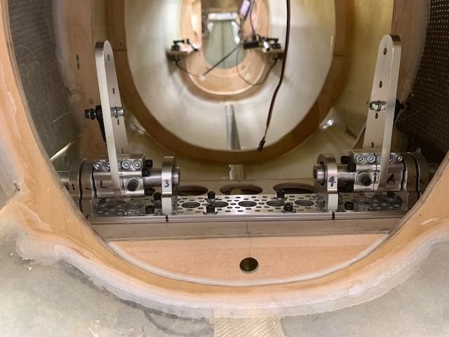
Both sides done. The purpose of the set screw is to be able to set the stab horns in exactly the same position each time they are assembled. The secondary purpose is to keep the stab tube from moving in or out. The servo torque is transferred to the tube by the clamp blocks not the set screw.
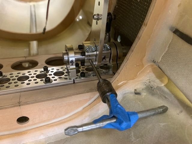
I had to cut off hex wrench to fit into the tight space in order to tighten the clamp bolts for final assembly. Its really bad to have to make special tools to do basic assembly. It's too complicated for my brain!
Clamp block bolts have to be tightened after assembly otherwise you cant slide the clamps on the tube.