Originally Posted by
Flite-Metal
Thank you for your post. All help is appreciated ... However...
Spoileron: While it is true NAVAIR 01-85ADA-1(1-45) refers to spoilerons as flaperons. All branches of the service tend to name/rename aerodynamic devices and functions to make it their own. Clicking Spoileron will link you to the aeronautical definition of that word/function.
Flaperon: Flaps which function through “X” % of the aileron movement. On the B-47 flaperon function in unison with the aileron until the aileron exceeds 25% of travel.
On the A6 series, they're called flapersons and speed brakes. I clicked on your "deceleron" link, and note that in the wikipedia article, which is hardly authoritative when it comes to nomenclature of a specific aircraft, only one of them was even related to a military source. And one does not make the argument. I'm struggling to understand why you're so wedded to nomenclature that is NOT reflected in the actual flight manual for the aircraft you're modeling.
Originally Posted by
Flite-Metal
Deceleron: Are devices originally intended to aid in roll control as well as reduce airspeed during final descent, Decelerons are typically located at or near wing tips due to the lack of available space elsewhere. We provide information for acrivating the decelerons. That area of the wing is a vacuum formed piece included with each model. We chose to not design in the deceleron due to someone could literally stall during the approach...aka crash. However functionality could be achieved if coupled to the electric brakes upon touchdown..
Not on this aircraft, which is probably why the manual calls them "speed brakes." I have no idea where you ever got the impression they were used to control roll on the A6 series. There is no differential deployment of the speed brakes on the actual aircraft. In fact, it's an emergency situation if they do (which means it's not supposed to happen). Having actually flown the aircraft, I can assure you that the top and bottom of each section extend in unison, and that's in unison with the ones on the other wing. They are not used for roll control, do not operate that way, and never have. Also, please explain how the speed brakes cause a stall. They add drag - period. They're no different in that sense than extending the landing gear - drag. If you didn't include them for simplicity purposes, that's fine, but they have no effect on stall speed (at least in the actual aircraft), they are not used for roll control, and are used to add drag only.
Originally Posted by
Flite-Metal
Flaps on the MAC6's are not extended trusses as found in the Fowler flap. Viewed from the top the MAC6's give the visual illusion of the Grumman A6 trusses ahead of each telescoping truss.
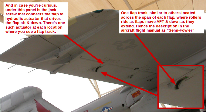
Not sure what an MAC6 is, but this statement is also incorrect. I have no idea what you mean by trusses. What I have said, and will repeat, is that the flaps on the A6 series aircraft are "semi-Fowler" - which explains why they were described as such in the flight manual. Plus, as you note from the photo below, the flap tracks are clearly visible. They're present at various locations along the span of each flap section, and there are physical rollers attached to each flap at these locations. When the jack screws are energized, they drive the flaps AFT and down - with the rollers riding in those tracks. Again, not sure why you're so determined to ignore what people who've actually flown the aircraft are telling you.
Originally Posted by
Flite-Metal
The 1:1 A6 flap leading edge is painted red because it is a pinch zone hazard.../QUOTE]
The red has nothing to do with pinch points. The surface underneath is red so that if they're partially extended or not fully retracted there's significant contrasting color that's easily visible from the cockpit or from another aircraft flying in formation. Could it have been blue or black instead? Sure, but the Navy chose red. It has nothing to do with pinch points.
QUOTE=Flite-Metal;12696995]Because the leading edge of the flap is exposed...its red surface contributes to an illusion the flap has moved rearward as it is lowered. The 1:1 image below looks the same as our flaps do.
It's not an optical illusion. Having thousands of A6 flap deployments, from the cockpit in flight, from the wingman position when flying formation, from the ground while watching my Airframers do maintenance, and even once while investigating a mishap, I can assure you it is not an optical illusion. They move AFT and down, and thus are, as described in the actual flight manual, are semi-Fowler flaps.
I really don't know why you are so intent on ignoring what the actual flight manual says or someone with over 2,000 hours actually flying the aircraft tell you about how the flaps work. If nothing else, I'd think it hurts you with potential customers, but if you want to cling to inaccurate word choice and ideas about the flight surfaces work, then go ahead. It's your credibility that gets damaged.