Hi guys, ZOMBIETHREAD here. I had plans for this on the SPAD forum, they never made it to the spadtothebone.org page like many one offs don't BUT then I found out I didn't have the original plans on my computer anywhere either. Bummer. So as I've been asked about the BustaHOR lately I thought I'd add the plans here and hope that we last a bit longer.
The BustaHOR I have is built with an RNAF style wing of 4 mil on the bottom and 2 mil on the top though 3 would work fine as well, whatever you can get. To glue the top sheet to the bottom sheet you need to flash both piece of coro with a butane torch. You just run the flame of the torch over the coroplast and it will burn off the mold release againt. There is a 1 inch overlap here. With the maiting edges of both pieces flashed, drops of CA are applied every inch or so along the joint, the piece pressed and held together. I use a metal yard stick with weights on it and leave it for the night. Afterwards, take a #2 screwdriver, run along the front edge of the bottom 4 mil to crease the top sheeting just in front of the joint, this will leave a bending edge that won't hit the top of the bottom sheet when you fold the top cover over. SPAD builders no this process by heart but newbies, slowly work from end to end to bend the top sheeting over onto the bottom sheet. Don't try to get it flat, you haven't glued your spar down yet AND going flat may pop your seem. Go Three inches back from the leading edge and glue your spar down by the same method as the sheeting. Mark your spar location, Flash the line with a torch AND do the aluminum to get rid of oils on it. Put drops of ca on the line every inch or so, press the spar down and it will more then likely be done in an instant. But I weight it down and come back in a bit while I cut out tailfins. Come back and bend the top sheet over the spar and hold it down to where it meets up with the trailing edge. You should have a little extra that we will trim off after glueing. Flash the trailing edges and where you think the spar will be, but drops of ca on top of the spar and on the trailing edge as before and bring the top sheet over. and weight it down on the trailing edge. I use bricks and come back the next day. A cautious builder could bond to the spar in one step then do the trailing edge in two steps. Be cautious, If you get good glue joints this sucker is going to last a good long time.
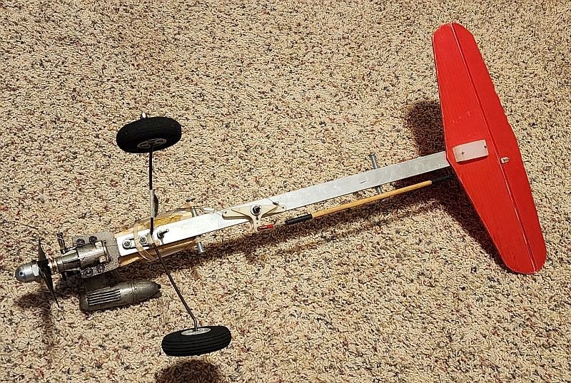
The horizontal and vertical are 4 mil. The fuse rail is standard big box store 1 x .5 aluminum C channel. I used half inch poly board for the engine mount and any doublers for wing hold down bolts/ bellcrank mount and Horizontal bracket/tailskid. The engine mount is cut to go inside the rail and I used Lath screws for Stucco mesh to mount the engine AND the landing gear to the fuse. (which has held up fairly well with years of balloon busting). The back of the engine is at half an inch in front of the rail and there is 1.5 inches of poly board into the rail. The front edge of the wing (front wing hold down bolts) is at 4 inchs. Bellcrank is 3 inches behind that and trailing edge screws are at 14.25 from the front of the channel. Some of these measurements may need to change for you if you use heavier 3 or 4 mil plastic for the top. I think the shortest piece of channel you can buy is 2 foot and mine is cut at 21.5" so you have some wiggle room. I think I have about 1.5 to 2 ounces of lead on the outboard tip. I had a big chunk, I wire tied it on and it flew. Very adjustable, put enough weight to fly level.
On the Vertical, the coro is mounted to the rail on by drilling through the rail,vertical and then screwing through the rail, the vertical and into a piece of pvc BUT you can use a piece of poly board for that too. You can probably use Pallet wood instead of Poly board if you do not have access to the half inch poly cutting board. Just paint it with thinned epoxy to fuel proof that.
I use a pressurized
 Fuse top and bottom showing bellcrank location under the fuse. You can also see the 2 inch block of poly that the rear hold down screws are mounted through the fuse and into.
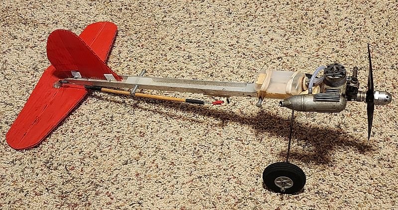
 Side view. There is offset built into the Vertical. I cut it free from the bottom as marked on the plans. Then I ran a piece of scrap pushrod in my drill through the back of the vertical through the area marked in two placed. Took the ground wire out of a piece of Romex electrical wiring and glued it into those holes. I removed one flute at the marked position and bent the rudder over a bit. It's kind of an old FF adjustable rudder trick. Been holding since 2008.
clunk tank on an OS 25 fp RC with the carb screw all the way down so the carb is open. Plenty of power for this on a 9x4 prop.
Rubber band the wings on, foam wheels to the size for your grass. Fairly tough trainer adn balloon bust plane. Flys inverted and does loops BUT have the engine leaned out for that, it is heavy though it flys really well for a trainer. It eats balloons with no care about sticks or ground strikes IT's SPAD tough.
Plans and photos time.
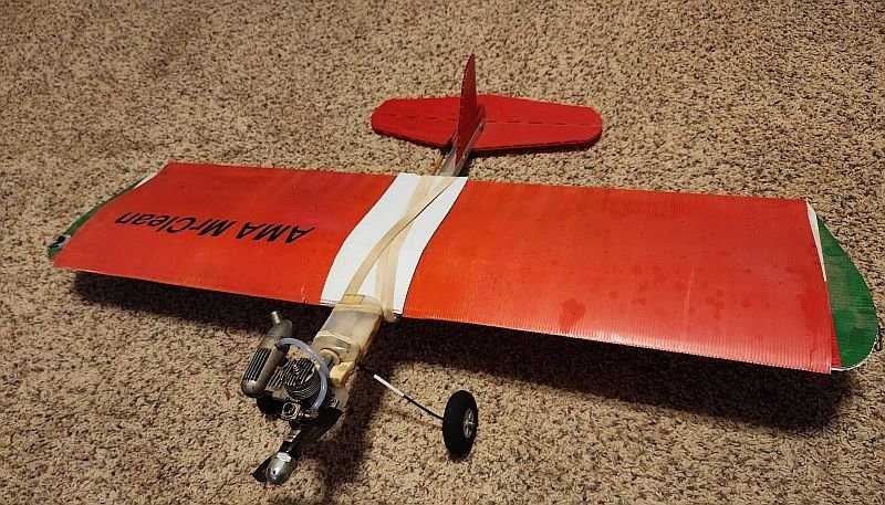 Front view
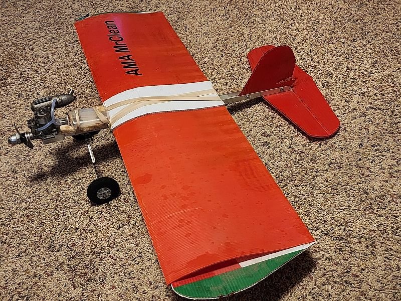
Side view I forgot to mention the white, 4 mil doubler over the center section of the wing for the rubber bands. Do cut and glue that on.
Side view
Front view
Side view I forgot to mention the white, 4 mil doubler over the center section of the wing for the rubber bands. Do cut and glue that on.
Side view
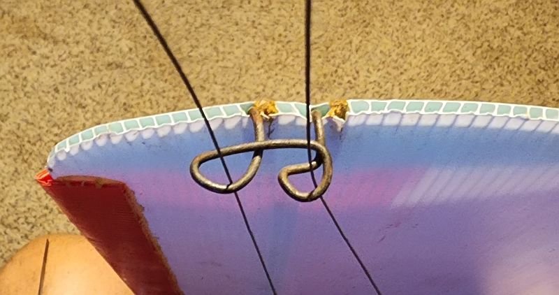 Leadouts, just some pushrod wire gooped into the flutes with some bamboo skewers to back it up
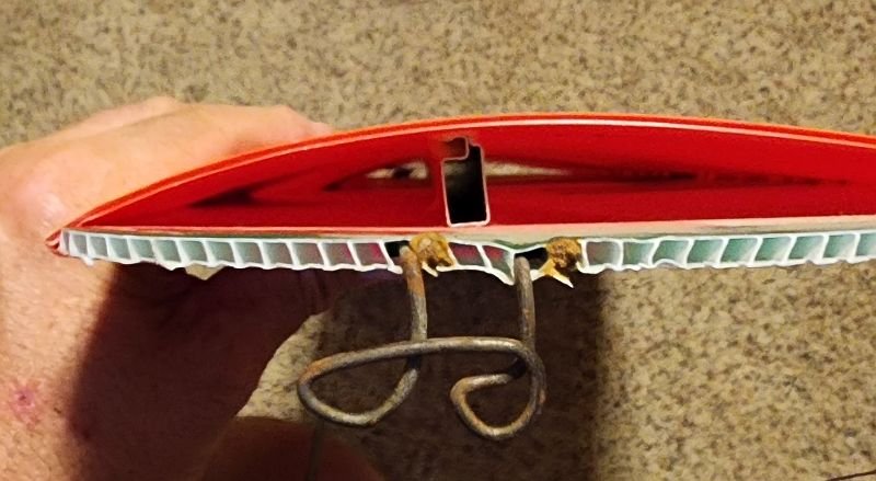 Looking through the wing at the screen window/door aluminum channel centered over the leadouts. This channel IS available at big box stores where you get your window screen repair pieces. You can cut down a yard stick it's 3/4 inch tall.
Fuse top and bottom showing bellcrank location under the fuse. You can also see the 2 inch block of poly that the rear hold down screws are mounted through the fuse and into.
Looking through the wing at the screen window/door aluminum channel centered over the leadouts. This channel IS available at big box stores where you get your window screen repair pieces. You can cut down a yard stick it's 3/4 inch tall.
Fuse top and bottom showing bellcrank location under the fuse. You can also see the 2 inch block of poly that the rear hold down screws are mounted through the fuse and into.
 And a view of the motor mount you cut out of Poly and the Lathe screw locations to hold the mount and the landing gear on. There is a long screw just behind the landing gear. Normally there is a rubber band around that, over the tank and back down. Being held on now by the wing mount hold down.
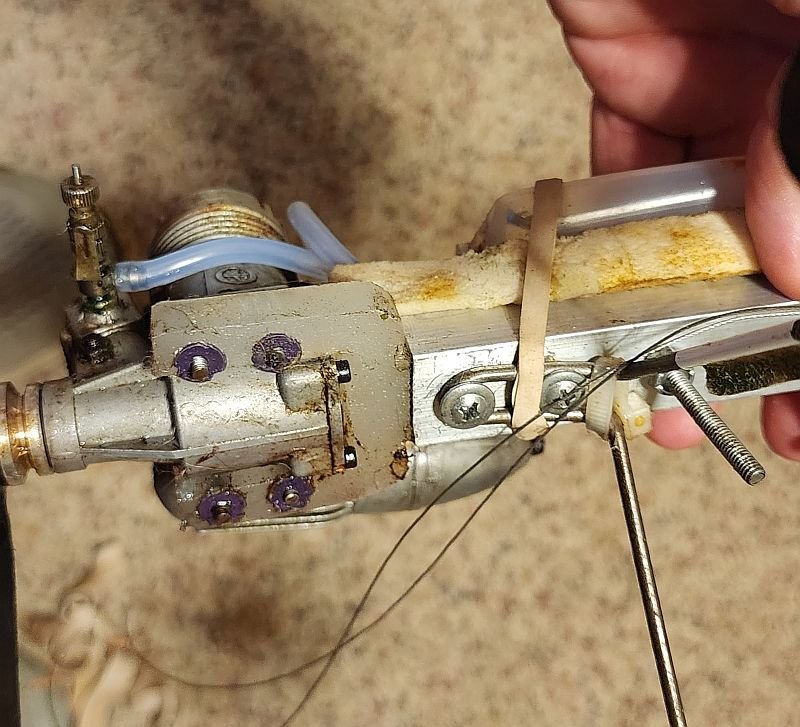 And just a closeup of that engine mount/landing gear setup.