Originally Posted by
jorgan
Hi Bert, thanks very much, looking forward to my delivery. Hope you get your hernia sorted, can't be nice.
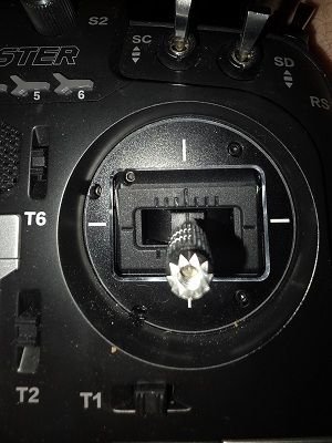
The throttle doesn't have any markings and the ratchet has 22 indents, so that's going to be fun, funnily enough the airelons have 7 markings, but I don't know if the rachet corresponds (no point looking). I'll have to make an inlay which will hopefully line up with the rachet. I suppose if the system is sensitive one notch may make a difference? Always something.
As a matter of interest what do the corresponding curves look like for the valve?
You can try making a temporary (or more permenent) index yourself, or you can perhaps do your testruns with the stickpositions "on screen"? Another option is to use the call-function, where activating the momentary switch (the one that springs back when you let go of it) to audibly call out the stick position.
As for the bolded: A bit confused, because I posted 3 examples of possible fuel curves (from 3 different engines)? Of the four curves I posted, the first one is a generic throttle curve. They all look like that, they all are a progressively increasing curve, individual differences are at best the value at midstick being slightly higher or lower, but they all start at -100, and end at +100 in a single progressive curve upwards.
The other three are fuel curves. They can look like anything, but common properties are that they are "smooth" (no strange spikes) and they usually have a vague S-shape like the 3rd pic from top, or a U shape like the last pic.
The first fuel curve (2nd pic from top) is a bit of an outlier with its sharp drop at the top of the throttle range, and I have no explanation as to why it is shaped like that, It is the only one of my engines that requires a cyrve like that...