Following the previous update on the completion of the Aurora wing, substantial progress has been achieved on the fuselage assembly.
The upcoming stages of the project will focus on the engine mounting structure, integration of the fuel tank bay, installation of the retractable nose landing gear, attachment of the belly pan, cutting of air intake and exhaust openings, fabrication of the control pushrods and servo mounting plate, and the installation and alignment of the horizontal stabilizer.
The engine installation began with cutting the enclosed pinewood mount rails. Using the construction plans and the provided sheet showing the mount outlines, I traced the contours and cut them with a Dremel Moto-Saw.
Simultaneously, the location of the F2 former was marked on the fuselage according to the plan and the same reference sheet. Since, in the case of this fiberglass fuselage, the position of this former can be shifted forward or aft relative to the plan, I double-checked the clearance ahead of the marked location to ensure that the engine, when mounted on the MK soft mount, would fit properly without interference with the nose ring or F2. I then cut the engine opening on the fiberglass floor, just ahead of the marked location.
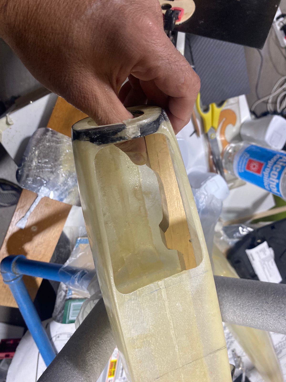

A cardboard mock-up of the F2 former was first cut to approximate dimensions and gradually trimmed until it fit perfectly against the fuselage sides, leaving no gaps. Once the final shape and dimensions were achieved, the definitive former was cut from 3 mm plywood. Similar to former F4, the front face was reinforced with a 1 mm carbon fiber plate, adding both strength and an enhanced appearance.
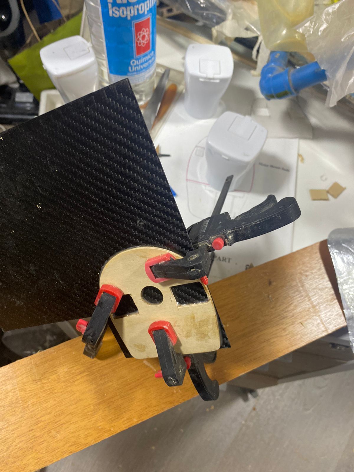
Alignment slots for the engine mounts were then cut into this former according to the plans. Longitudinal reference lines were traced along the fuselage sides to serve as a guide for the slight engine downthrust specified in the plan.
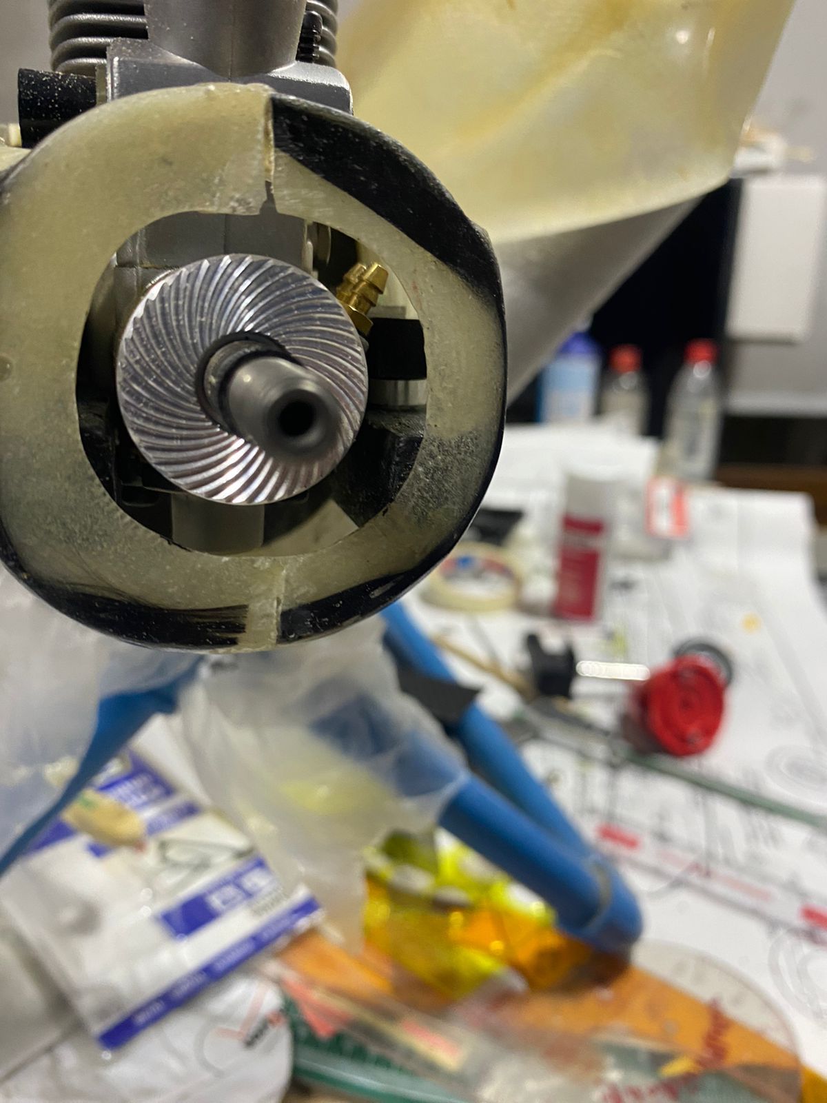
Next, time was spent adjusting the width of the mount rails so that the engine—already assembled on the MK rubber mount—would fit snugly. Space within the forward fuselage is quite limited, and the YS engine fits precisely with minimal clearance. Some internal side trimming of each mount was also required to ensure the engine crankcase seated without interference.

Both mounts were then tack-glued in the calculated position along both axes, taking into account the longitudinal alignment lines traced on the fuselage sides and the additional height introduced by the MK mount relative to the engine axis. This tack-gluing and fitting process had to be iterated twice to achieve a perfect fit, ensuring the correct downthrust angle. The final vertical position of the engine was verified by temporarily installing a spinner of the required diameter to confirm a smooth transition with the fuselage contour.
The exact horizontal positioning, accounting for the specified side thrust, was left for a later stage, once the engine could be fully bolted to the mounts.