


RCaiir Aurora 60 Build
 12-20-2025 | 07:59 PM
#26
As with most designs from that era, the Aurora features a tank bay with limited access behind the wing-attachment former. Additionally, the nose retract is mounted directly to the tank floor. This configuration restricts access to several critical components that should remain easily serviceable for troubleshooting or maintenance.
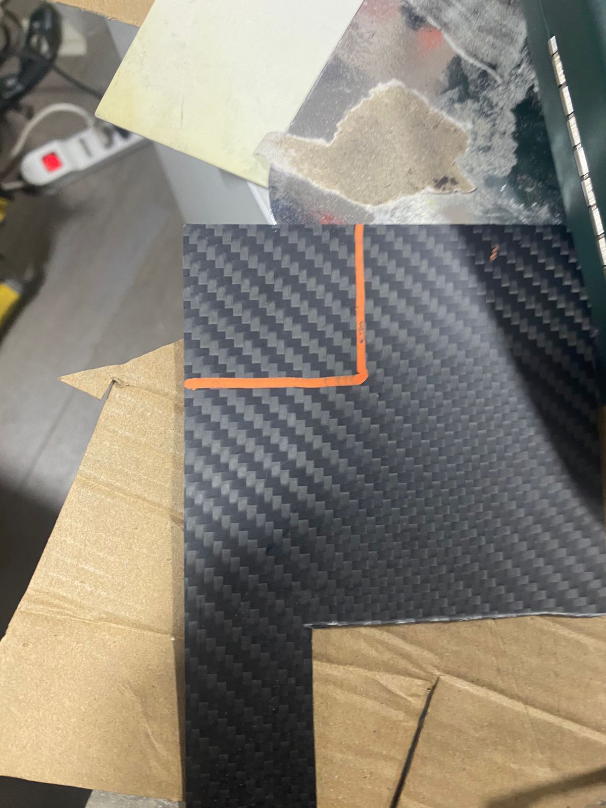
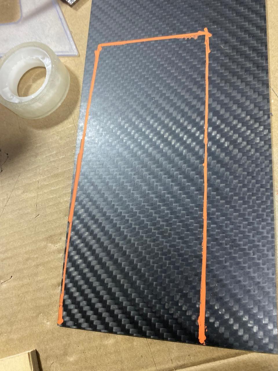
To address this, I decided to make the tank floor removable. Because the tank floor is molded into the fiberglass fuselage, it had to be cut out. Instead of reusing the removed fiberglass section, I opted to fabricate a carbon-fiber plate of appropriate thickness—stiff and strong enough to serve both as the new tank floor and to withstand the loads transmitted by the nose retract during landings.
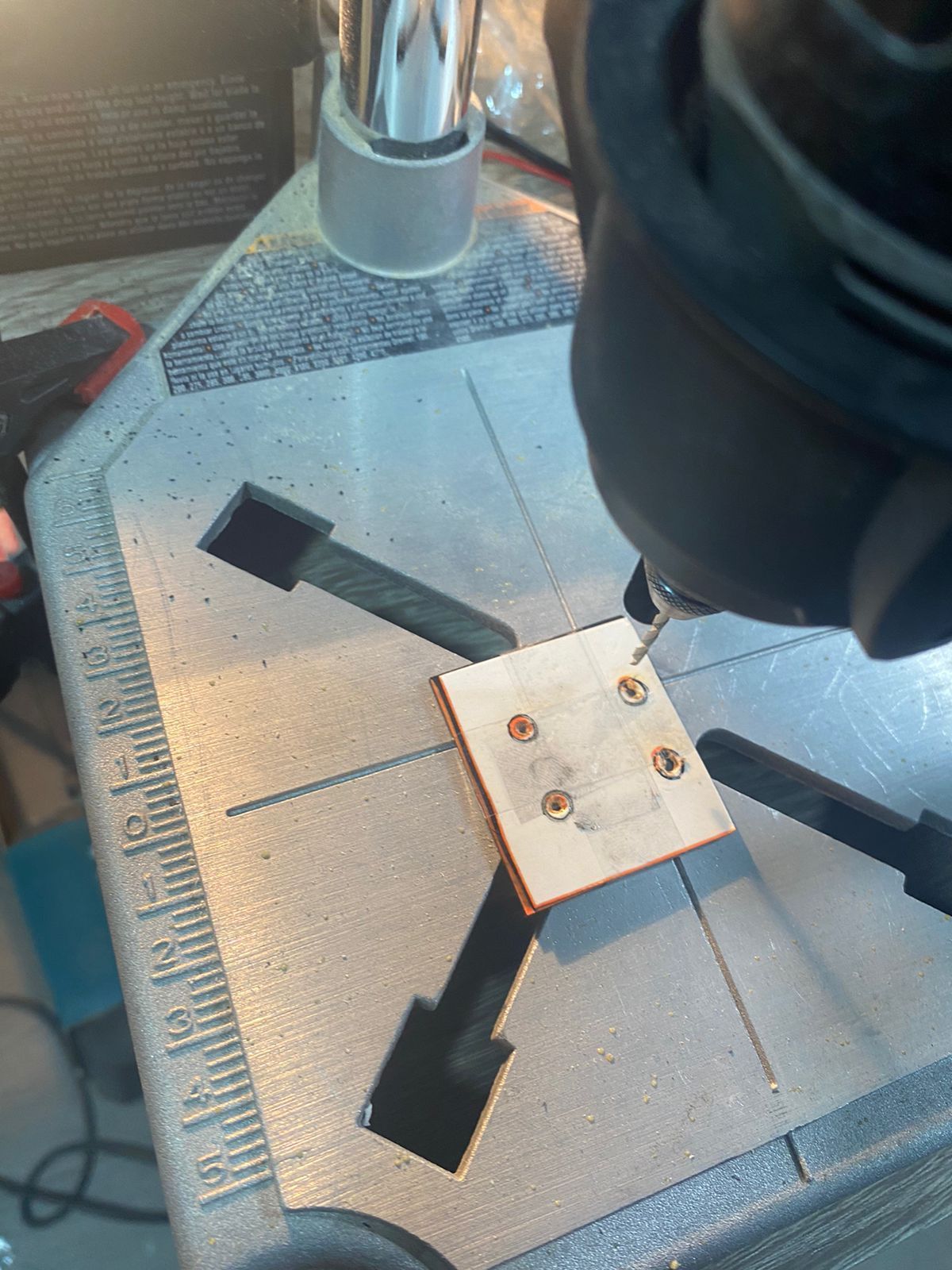
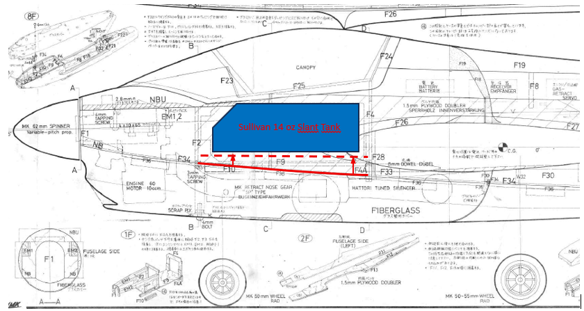
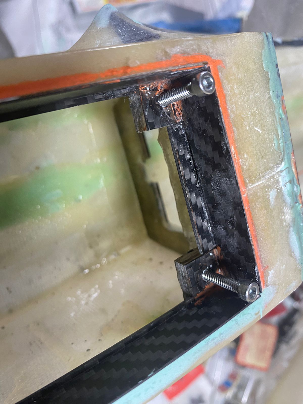
I then planned the layout of the removable floor panel so the selected Sullivan 14 oz slant tank could be extracted from behind and from below the tank bay. In terms of the door length, I also needed to account for fastening hardware. I chose to fasten the floor using 6-32 bolts and matching blind nuts installed on hardwood blocks and glued to the tank walls.


At this point, two issues emerged regarding the nose retract. The first concern was the retract pivot point. Because the Aurora has a belly pan, this pivot point sits a couple of inches above the outline of the belly pan. As a result, it makes a significant difference whether the retract mounting plate is positioned above or below the pivot point.
In this case, the electric retract came with a plastic mounting plate located below the pivot axis. With this configuration, the retract would have to be recessed into the tank floor, and a wheel bay cavity would also be required inside the fuel tank floor to accommodate the geometry.
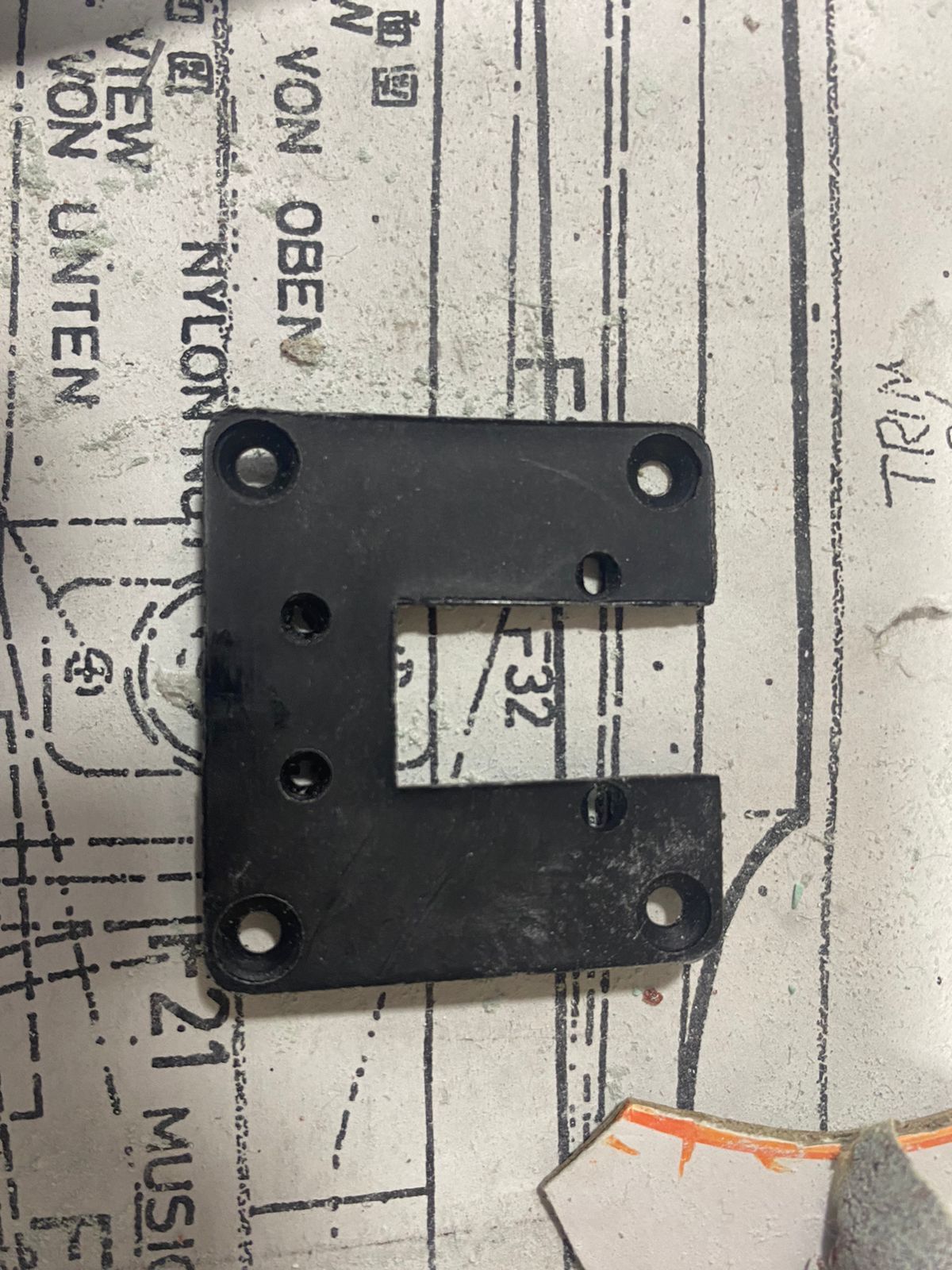
I addressed this by noting that the retract also included threaded inserts on its upper side. I initially assumed I could simply remove the bottom plate and relocate it on top; however, the hole spacing did not match. To resolve this, I fabricated a new carbon fiber mounting plate with the correct hole spacing, allowing the retract to be mounted above the pivot point instead. First issue solved.
Original plastic retract mounting plate
Original retract plate position
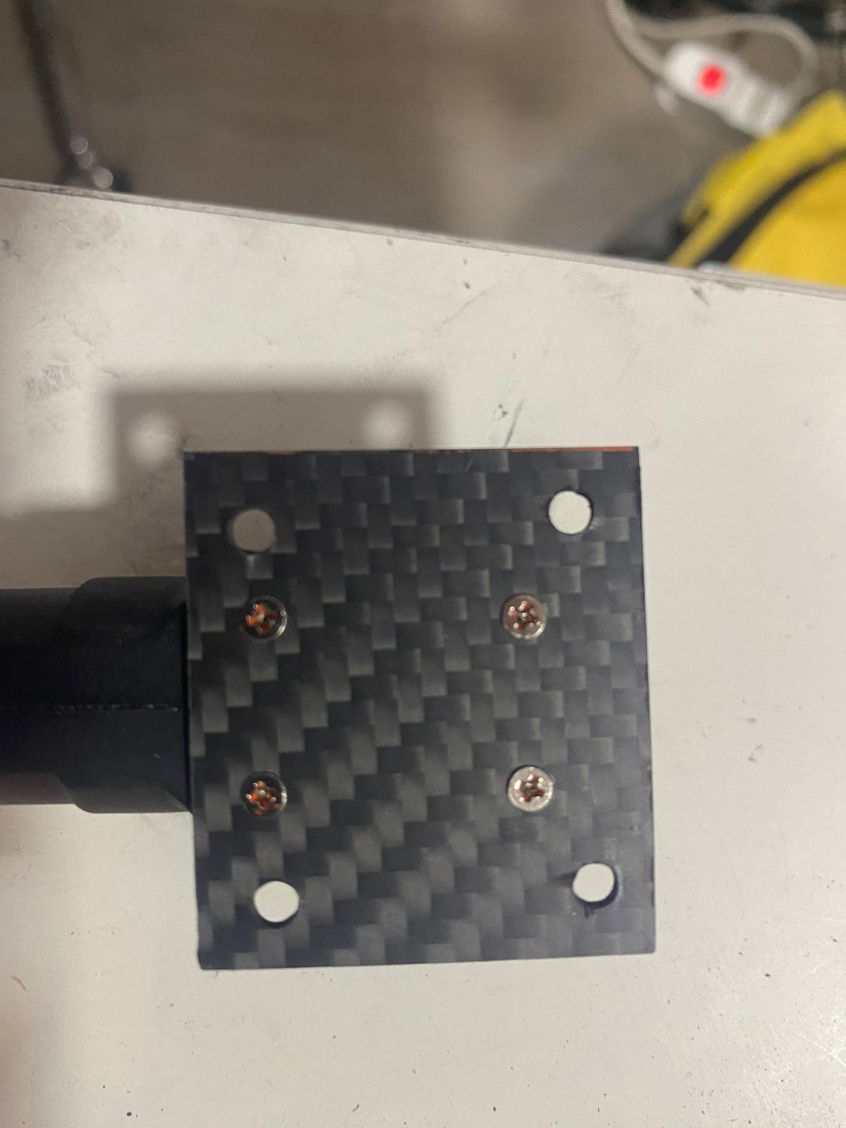
Carbon fiber made mounting plate

Final retract plate position
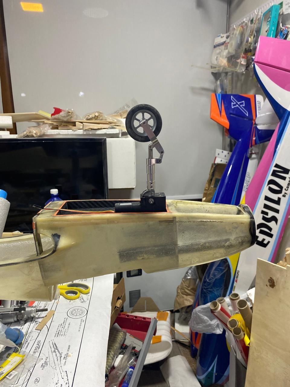
However, placing the retract—with the new mounting plate—flush under the tank floor left only 11 cm between the bottom of the retract and the ground. Accounting for geometry, this meant the strut could be no longer than about 7.5 cm:
Instead, I opted for a better solution: raise the tank floor door (this also brought an additional benefit that I will explain later.)
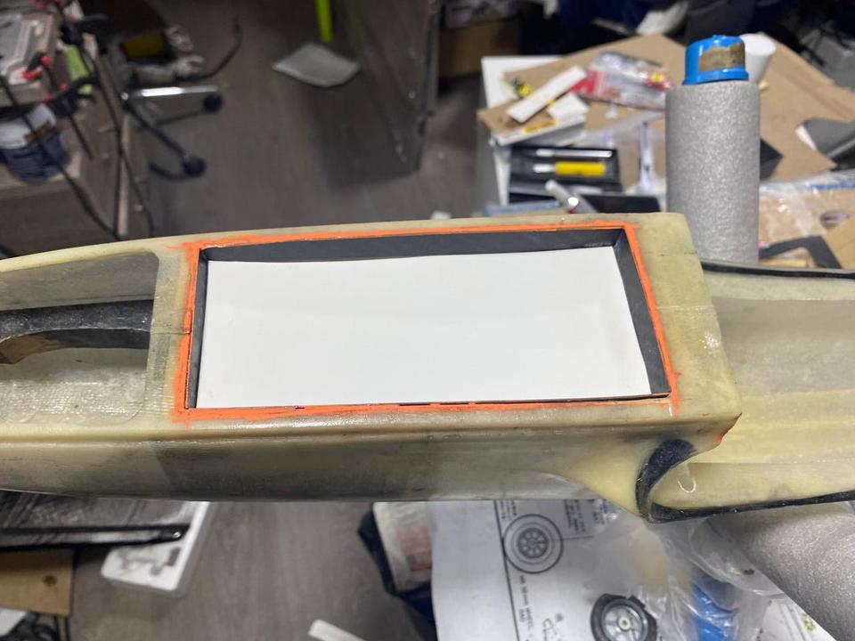
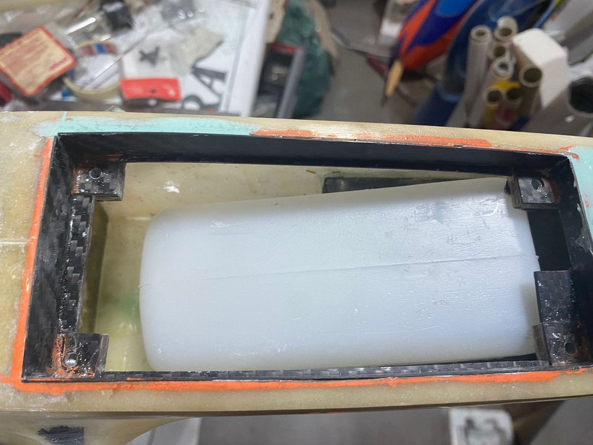
Because the Sullivan tank was shorter in height than the original MK fuel tank, raising the floor proved to be an even better option. Ultimately, I had about 1.8 cm of vertical tolerance to raise the tank floor—an acceptable amount considering the spring-damped struts will compress some millimeters under the aircraft weight.
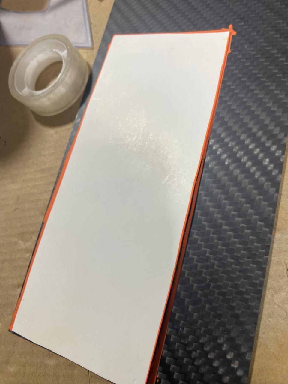
The results are shown in the photos. I also clad the external walls created by the raised tank floor in 0.5 mm carbon fiber sheet, both to maintain a clean appearance and to provide fuel resistance to the area.

To address this, I decided to make the tank floor removable. Because the tank floor is molded into the fiberglass fuselage, it had to be cut out. Instead of reusing the removed fiberglass section, I opted to fabricate a carbon-fiber plate of appropriate thickness—stiff and strong enough to serve both as the new tank floor and to withstand the loads transmitted by the nose retract during landings.
I then planned the layout of the removable floor panel so the selected Sullivan 14 oz slant tank could be extracted from behind and from below the tank bay. In terms of the door length, I also needed to account for fastening hardware. I chose to fasten the floor using 6-32 bolts and matching blind nuts installed on hardwood blocks and glued to the tank walls.
At this point, two issues emerged regarding the nose retract. The first concern was the retract pivot point. Because the Aurora has a belly pan, this pivot point sits a couple of inches above the outline of the belly pan. As a result, it makes a significant difference whether the retract mounting plate is positioned above or below the pivot point.
In this case, the electric retract came with a plastic mounting plate located below the pivot axis. With this configuration, the retract would have to be recessed into the tank floor, and a wheel bay cavity would also be required inside the fuel tank floor to accommodate the geometry.
I addressed this by noting that the retract also included threaded inserts on its upper side. I initially assumed I could simply remove the bottom plate and relocate it on top; however, the hole spacing did not match. To resolve this, I fabricated a new carbon fiber mounting plate with the correct hole spacing, allowing the retract to be mounted above the pivot point instead. First issue solved.
Original plastic retract mounting plate
Original retract plate position
Carbon fiber made mounting plate
Final retract plate position
However, placing the retract—with the new mounting plate—flush under the tank floor left only 11 cm between the bottom of the retract and the ground. Accounting for geometry, this meant the strut could be no longer than about 7.5 cm:
- 1 cm for the steering arm height
- 2.54 cm wheel radius (1" radius wheel per the plans)
Instead, I opted for a better solution: raise the tank floor door (this also brought an additional benefit that I will explain later.)
Because the Sullivan tank was shorter in height than the original MK fuel tank, raising the floor proved to be an even better option. Ultimately, I had about 1.8 cm of vertical tolerance to raise the tank floor—an acceptable amount considering the spring-damped struts will compress some millimeters under the aircraft weight.
The results are shown in the photos. I also clad the external walls created by the raised tank floor in 0.5 mm carbon fiber sheet, both to maintain a clean appearance and to provide fuel resistance to the area.
Last edited by Southern Flyer; 12-21-2025 at 05:15 AM.

The following users liked this post:
CoolCanuck (12-23-2025)

The following users liked this post:
Southern Flyer (12-21-2025)
12-23-2025 | 10:52 AM
#28

Joined: Feb 2012
Posts: 19
Received 0 Likes
on
0 Posts
From: CANADA - a Country, not a State
What / who's strut are you using?
Isn't it funny how things have changed from the days of yore using music wire on the retracts? They were lighter then... but it was a hassle bending them back to shape after a bouncy landing...
Looking good. Will keep the CF mount in mind for a current project.
Isn't it funny how things have changed from the days of yore using music wire on the retracts? They were lighter then... but it was a hassle bending them back to shape after a bouncy landing...
Looking good. Will keep the CF mount in mind for a current project.
 01-01-2026 | 11:42 AM
#30
Joined: Feb 2012
Posts: 19
Received 0 Likes
on
0 Posts
From: CANADA - a Country, not a State
Quite a number of F3A planes in those days had an offset nose gear. But not all went the same direction iirc. Hence the reason Hatori had them "bent left" and "bent right", as well as differences in the drop / rise. Yea, electrics make all those redundant and we can now have a centered nose gear and no worries about header & pipe clearances.
01-03-2026 | 08:33 AM
#31
Happy New year for everyone, I hope it comes with plenty of construction projects !
Entering one more year on the Aurora build but completion is now much closer.
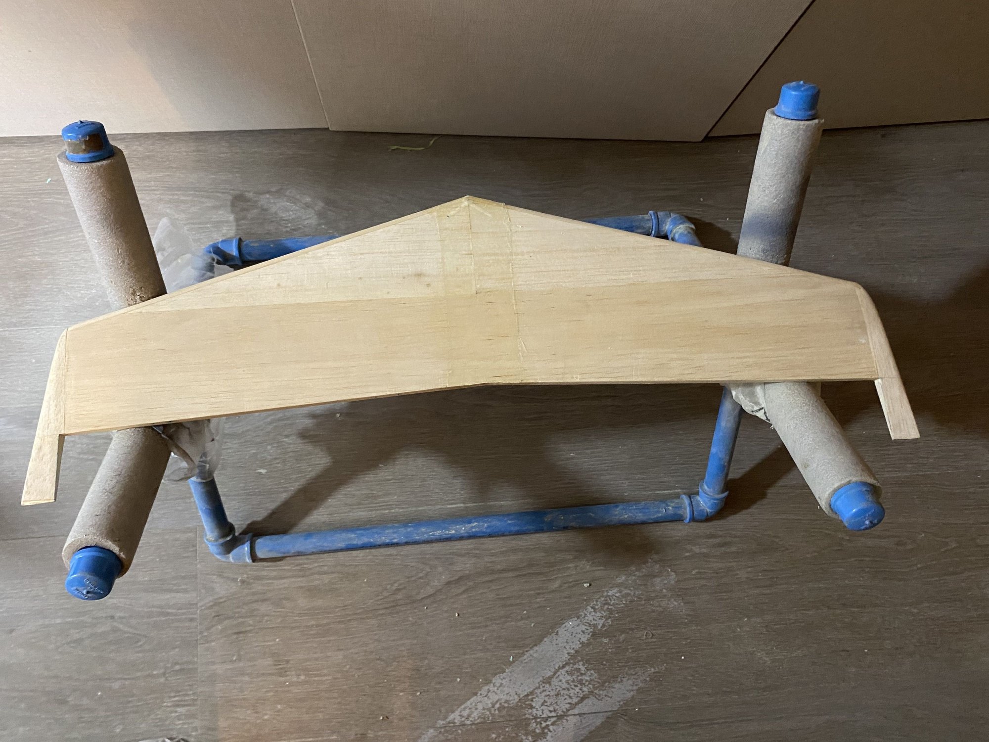
I realized that I had skipped the horizontal stab build steps, so now I will post them here.
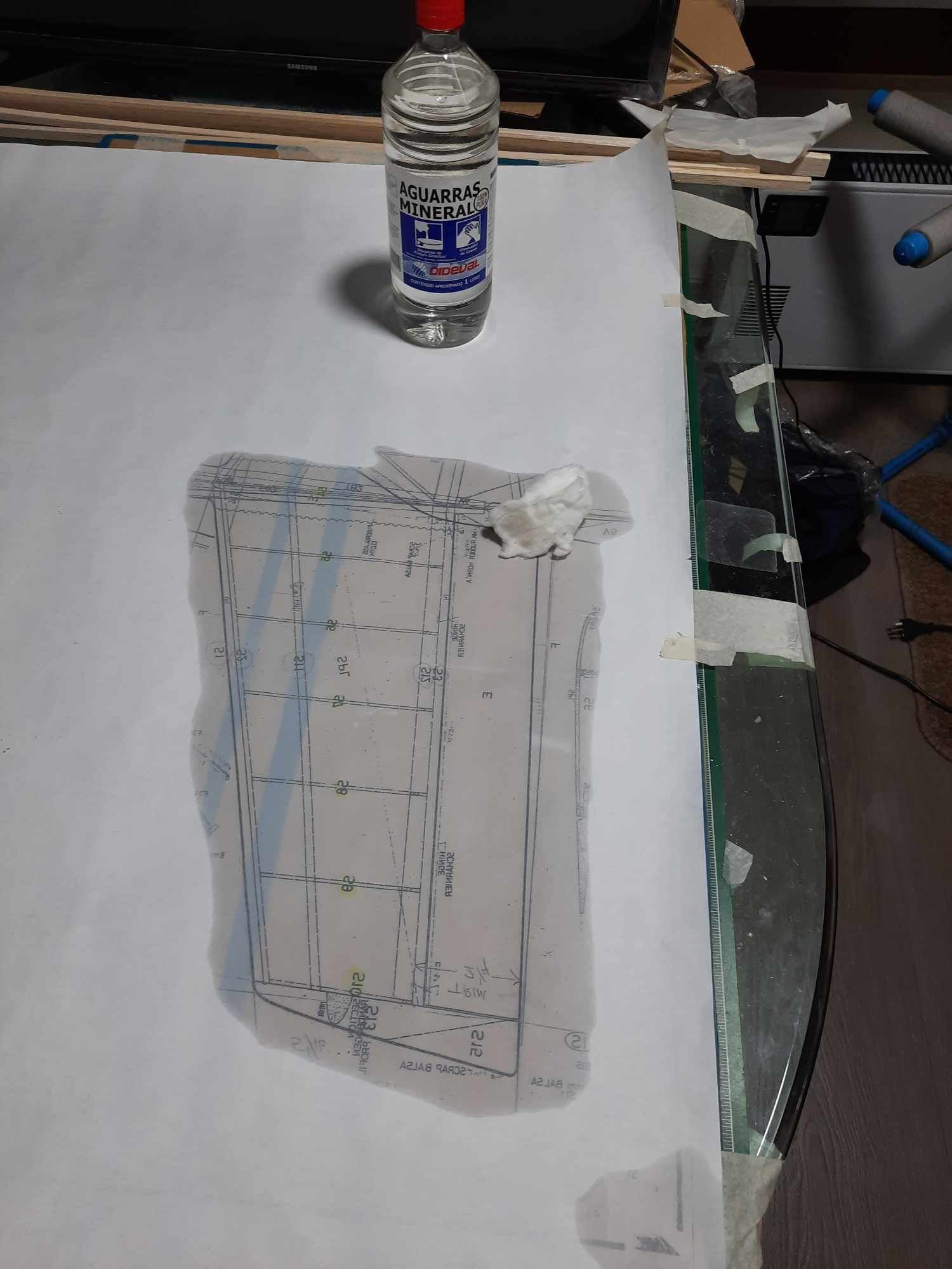
The stab was built at the same time with the initial stages of the wing, so it has been completed and sitting around for quite a time, but as the next steps on the fuselage are related to the mounting of the stab, I need to catch up with its build .
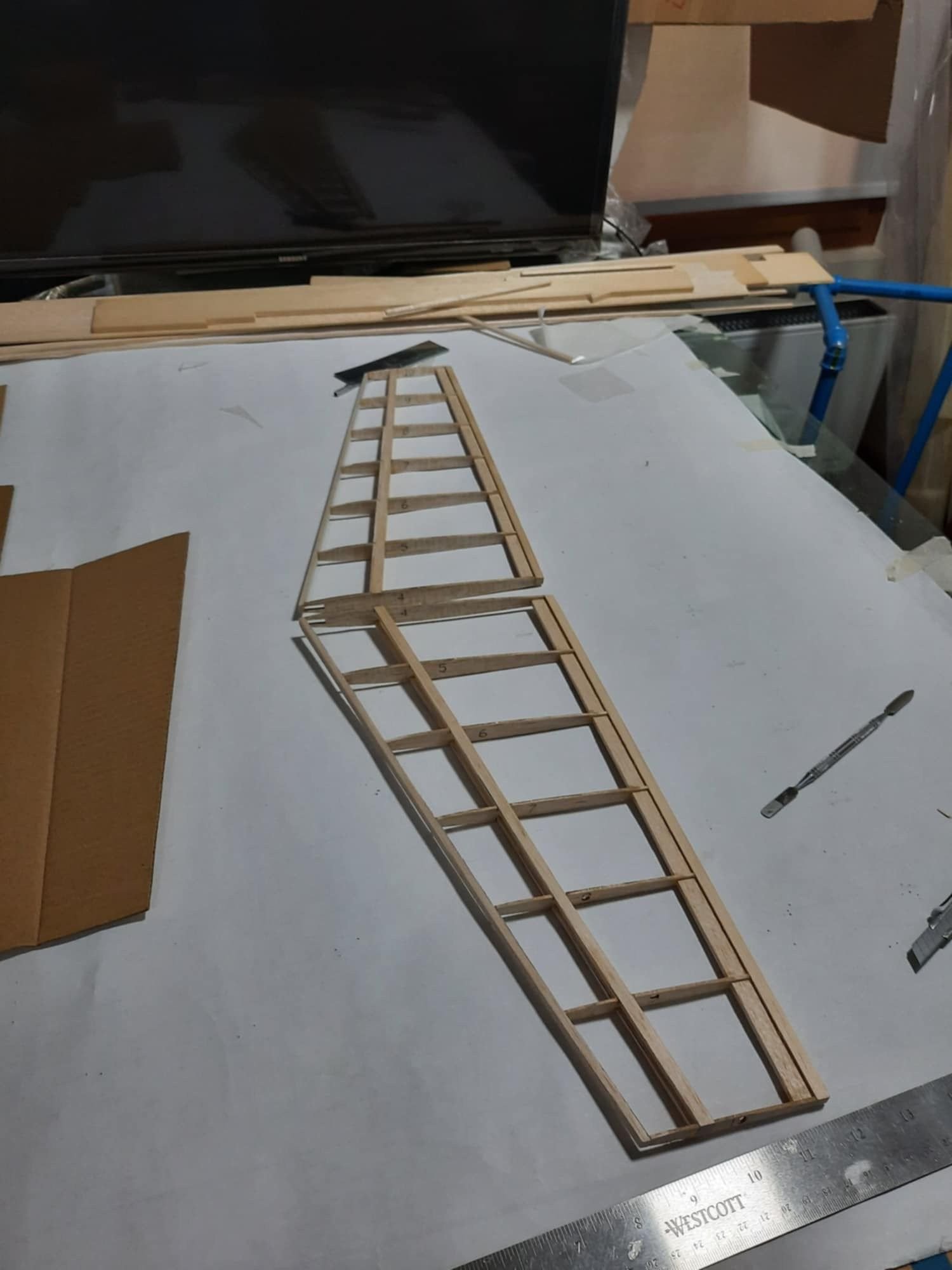
The build is very simple and it follows the initial build steps of the wing. The ribs come laser cut with tabs on its ends that provide the adequate positioning vertically wise. Basically you just glue the upper and lower spars and then add the sub leading and trailing edges, same as the wing. Top and bottom balse sheeting are then glued and the leading and trailing edges glued and sanded to shape. The stab wing tips blocks were glued and sanded to shape as well.
The balsa elevator halves were not supplied in the kit so I was a little disappointed given the price I paid for the kit, but finally not a big issue, I just supplied my own.
The final step was to add a fiberglass cloth reinforcement with epoxy resin at the stab center section as per the plan (also not supplied), this completes the horizontal stab build.

Entering one more year on the Aurora build but completion is now much closer.
I realized that I had skipped the horizontal stab build steps, so now I will post them here.
The stab was built at the same time with the initial stages of the wing, so it has been completed and sitting around for quite a time, but as the next steps on the fuselage are related to the mounting of the stab, I need to catch up with its build .
The build is very simple and it follows the initial build steps of the wing. The ribs come laser cut with tabs on its ends that provide the adequate positioning vertically wise. Basically you just glue the upper and lower spars and then add the sub leading and trailing edges, same as the wing. Top and bottom balse sheeting are then glued and the leading and trailing edges glued and sanded to shape. The stab wing tips blocks were glued and sanded to shape as well.
The balsa elevator halves were not supplied in the kit so I was a little disappointed given the price I paid for the kit, but finally not a big issue, I just supplied my own.
The final step was to add a fiberglass cloth reinforcement with epoxy resin at the stab center section as per the plan (also not supplied), this completes the horizontal stab build.
Last edited by Southern Flyer; 01-03-2026 at 08:38 AM.
01-11-2026 | 07:48 AM
#32
The horizontal stabilizer portion of the build continues with its positioning in the fiberglass fuselage and the preparation and installation of the structure I designed to secure the stabilizer in place.
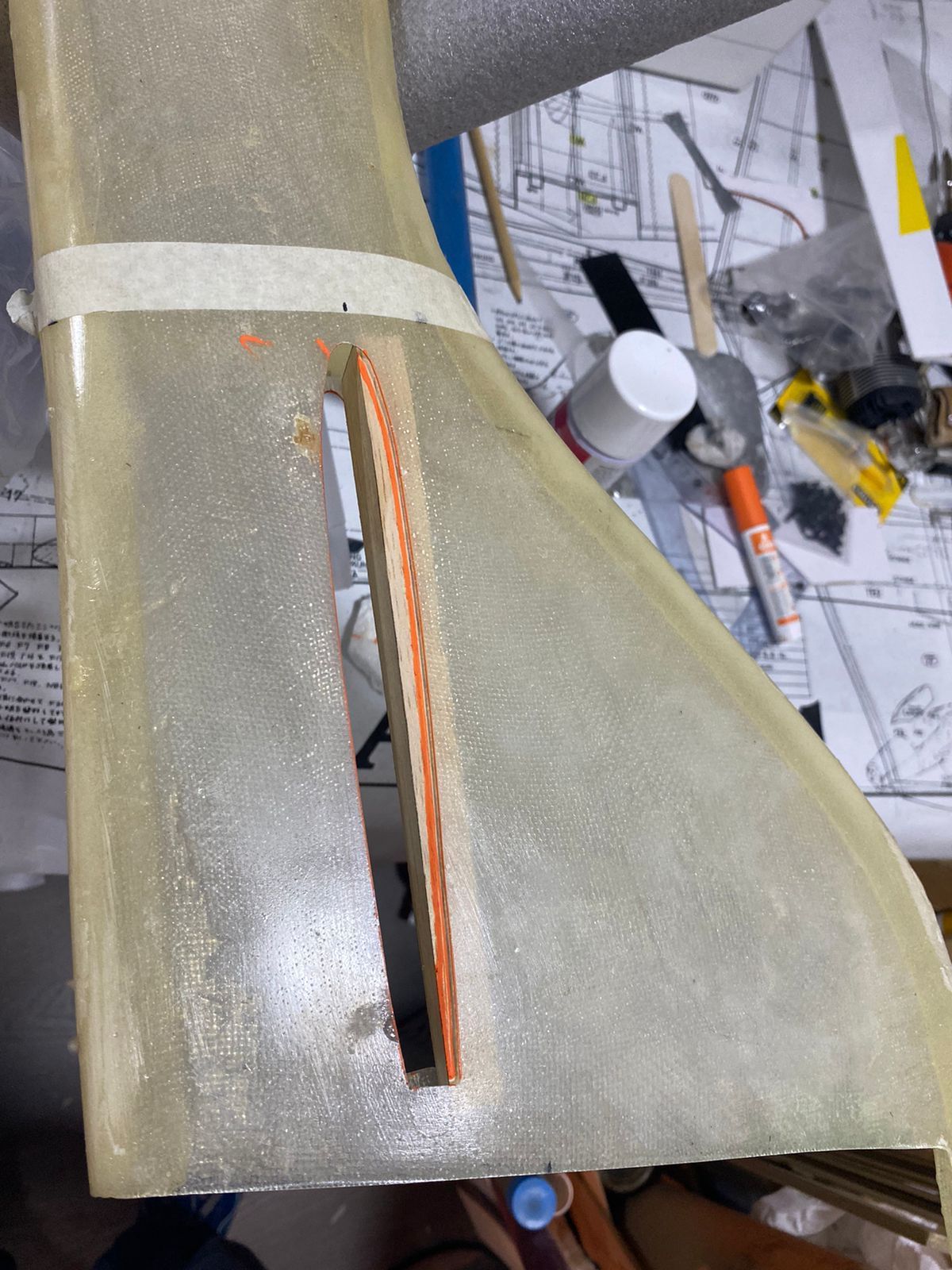
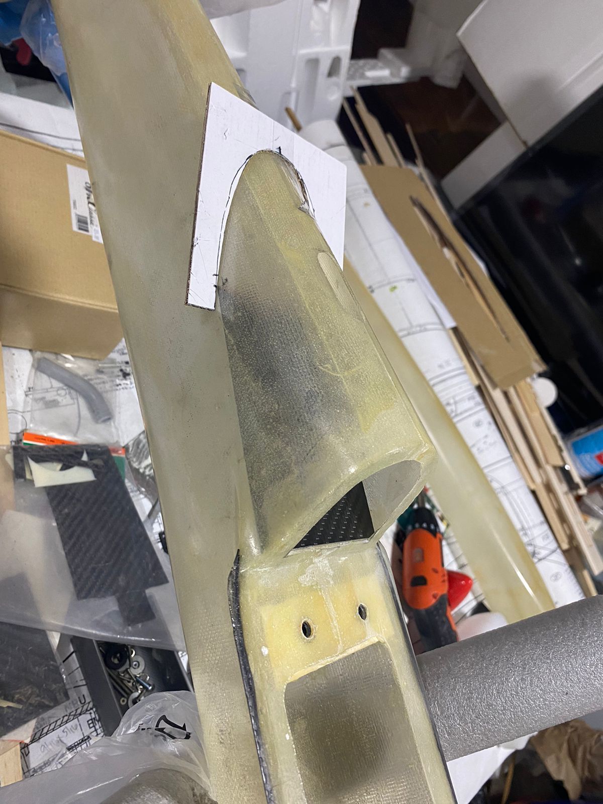
The first step was the careful positioning and marking of the fuselage openings for the stabilizer. The opening profile and location were transferred from the plans, and the stabilizer incidence was also marked according to the drawings. The openings were then cut using a combination of Dremel bits and cutting discs.
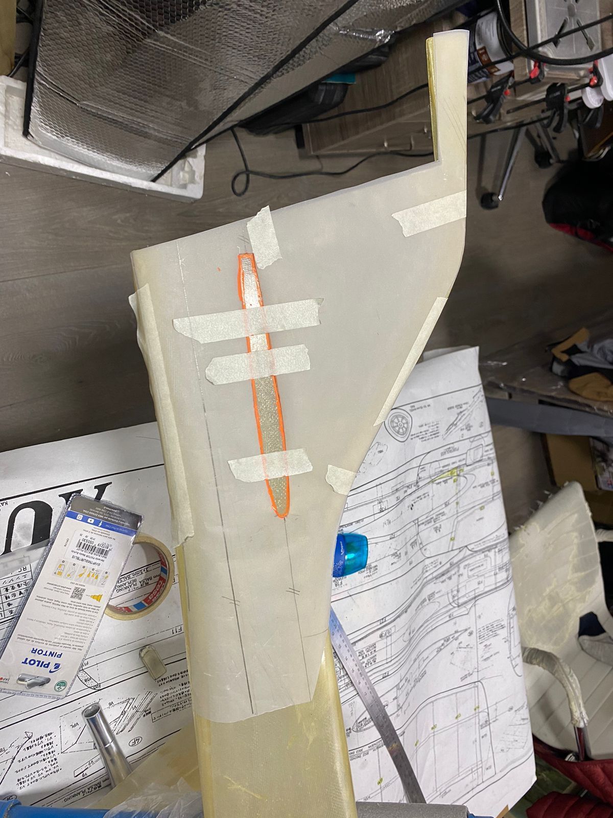


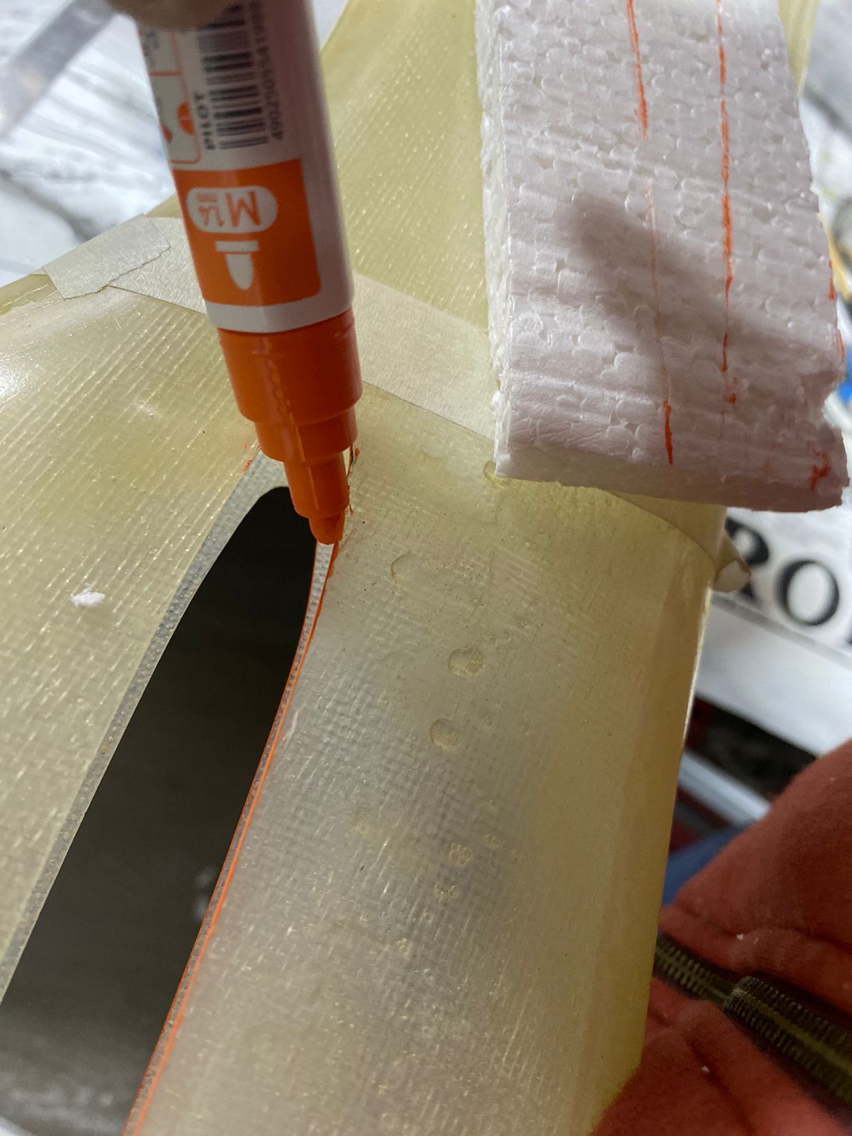
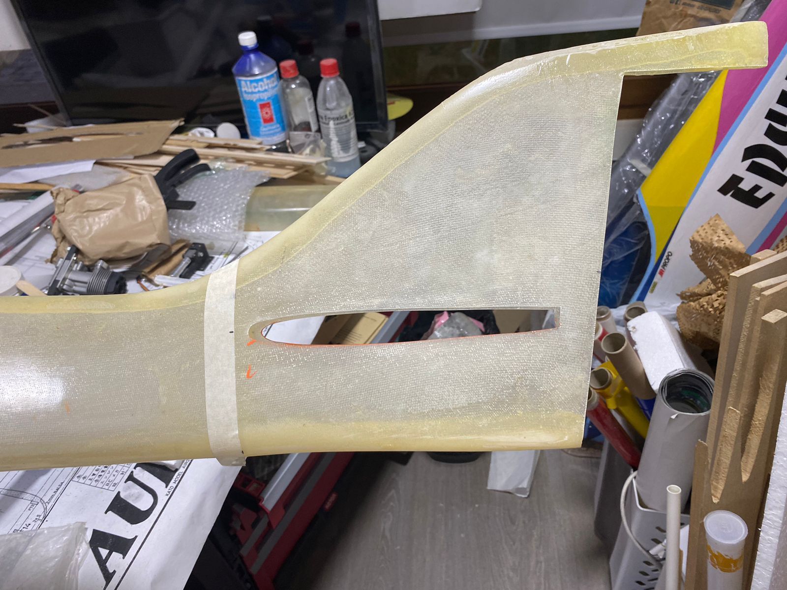
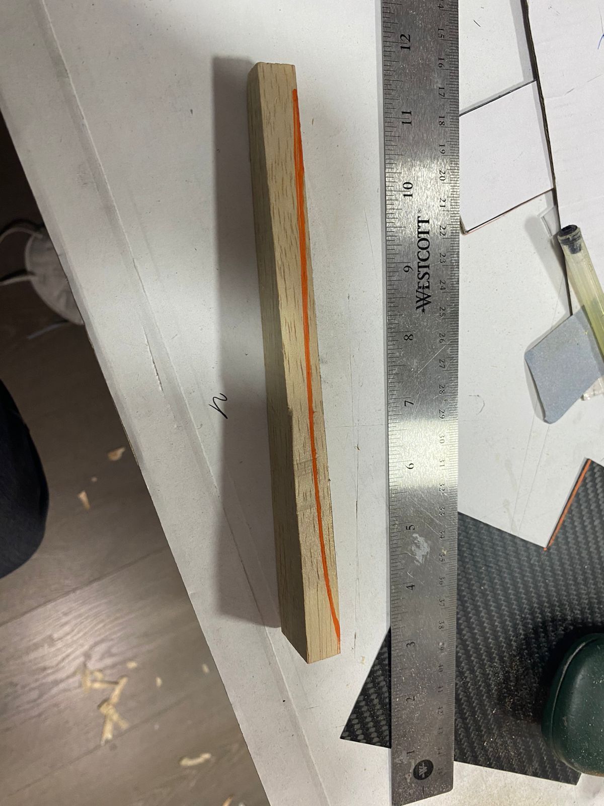
Since the original fuselage design is all balsa, I considered the thin fiberglass walls alone to be insufficient to properly support and retain the stabilizer. To address this, I fabricated upper and lower hard balsa reinforcement strips, which were sandwiched between the fiberglass fuselage walls. The stabilizer airfoil profile was cut into these strips prior to installation. Once glued in place, they were carefully sanded until a precise fit was achieved.

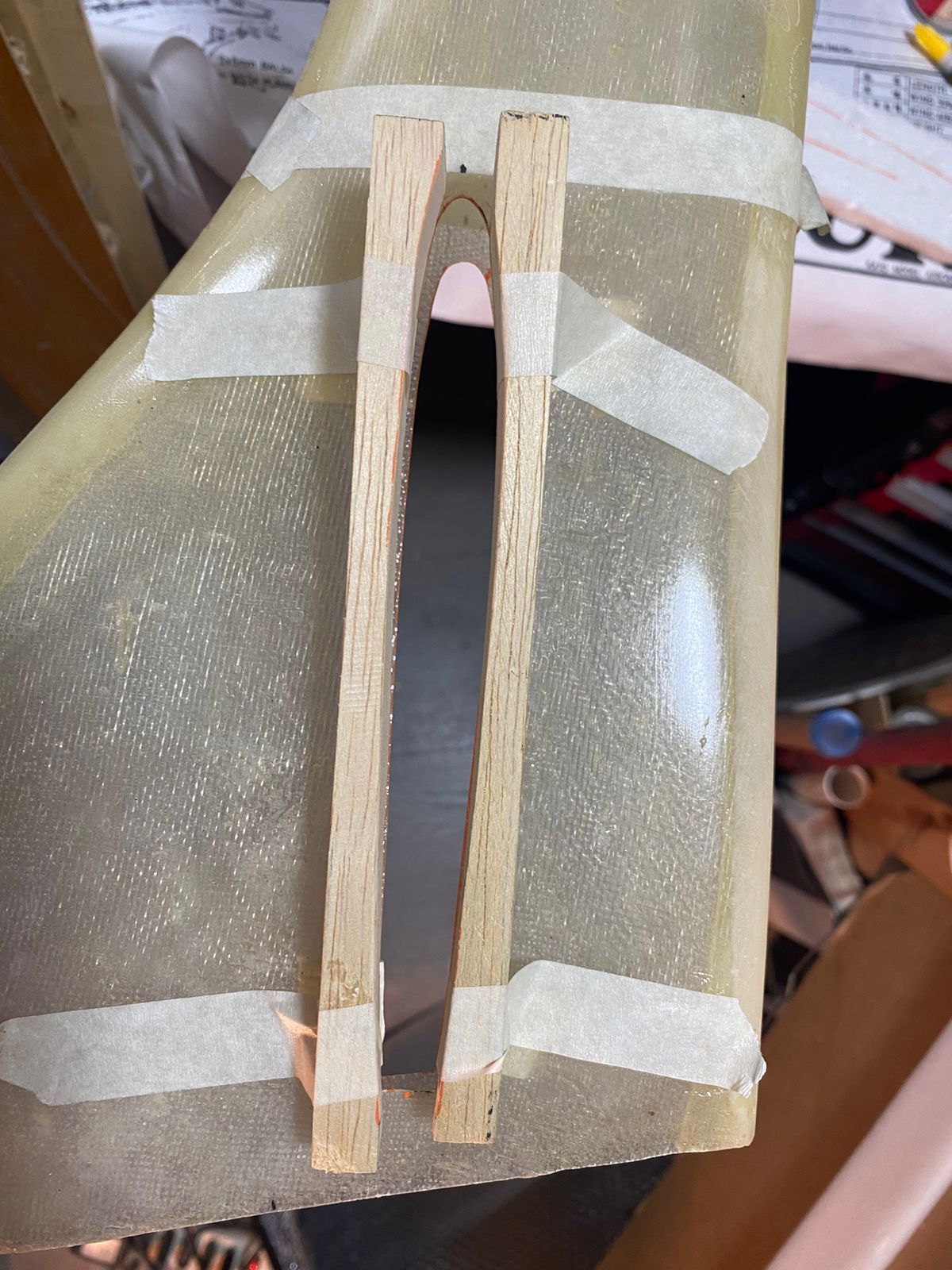
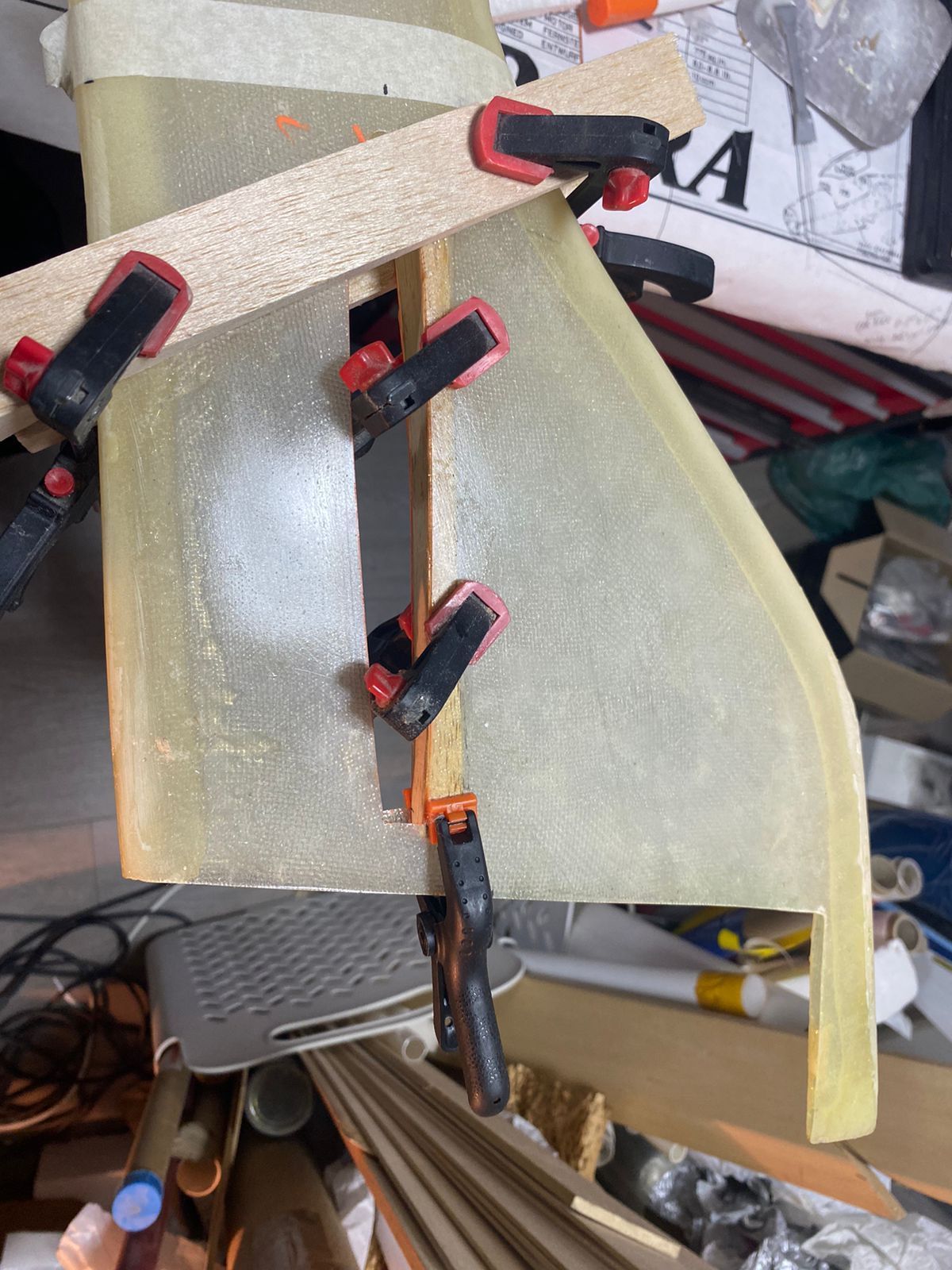
The fit was intentionally not made overly tight, allowing sufficient clearance for epoxy when final bonding is carried out later, after the stabilizer is covered and the fuselage is painted.
The first step was the careful positioning and marking of the fuselage openings for the stabilizer. The opening profile and location were transferred from the plans, and the stabilizer incidence was also marked according to the drawings. The openings were then cut using a combination of Dremel bits and cutting discs.
Since the original fuselage design is all balsa, I considered the thin fiberglass walls alone to be insufficient to properly support and retain the stabilizer. To address this, I fabricated upper and lower hard balsa reinforcement strips, which were sandwiched between the fiberglass fuselage walls. The stabilizer airfoil profile was cut into these strips prior to installation. Once glued in place, they were carefully sanded until a precise fit was achieved.
The fit was intentionally not made overly tight, allowing sufficient clearance for epoxy when final bonding is carried out later, after the stabilizer is covered and the fuselage is painted.
Last edited by Southern Flyer; 01-11-2026 at 07:56 AM.
01-19-2026 | 01:43 PM
#33
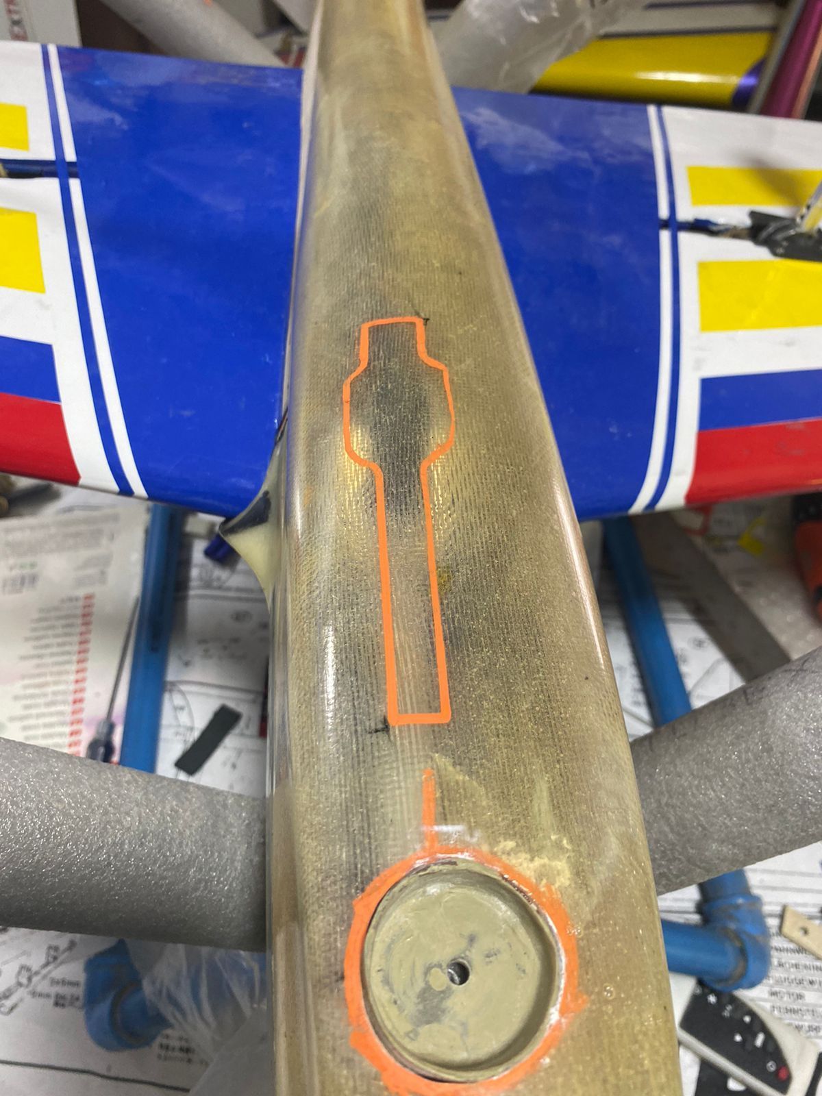
Fuselage construction continued with the belly pan attachment.
As shown in the photos, the lower front section of the fuselage has a built-in recess step of approximately 3 mm in the lower sidewall area, which secures the belly pan laterally. On the right side, I had to correct the fit by adding fiberglass putty to close a noticeable gap when fitting the belly pan, which required some additional work later at the finishing stages.
For the front attachment, I partially followed the method suggested in the plans, which uses an S-shaped metal beam bolted to the tank floor and to the belly pan. Instead, I used a 10 mm diameter carbon-fiber tube cut to the required height, with a 4 mm blind nut bonded inside.During horizontal positioning of this beam, care was taken to avoid interference with the nose retract (not yet in its final position) and the engine pipe header. As previously noted by someone, the nose retract on the Aurora—and on many designs of that era—is offset to one side (left) to clear the pipe header. However, it was still necessary to determine the correct offset to both meet this requirement and allow unobstructed operation of the steering arm assembly that was very close to the belly pan sidewall.
After trial-fitting all components, I determined that the retract mount needed to be positioned as far left as possible (viewed from the front) on the tank floor plate I had cut earlier. The carbon-fiber tube beam also needed to be slightly offset from the centerline. While this offset might have been avoided by using the metal S-beam, I still wanted to try this solution and considered the metal beam somewhat flimsy.
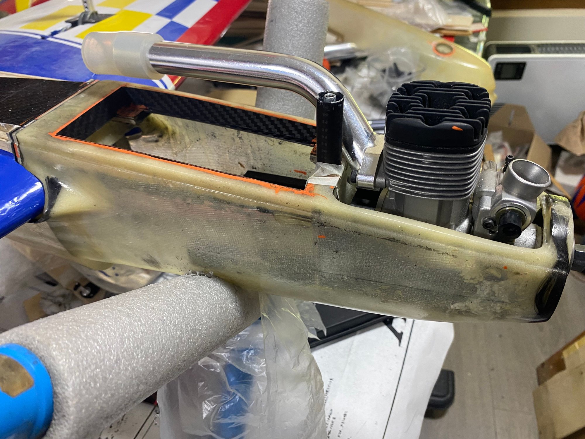

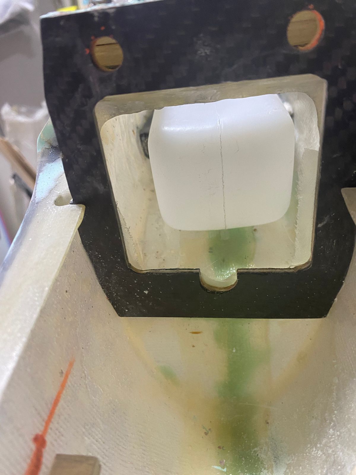
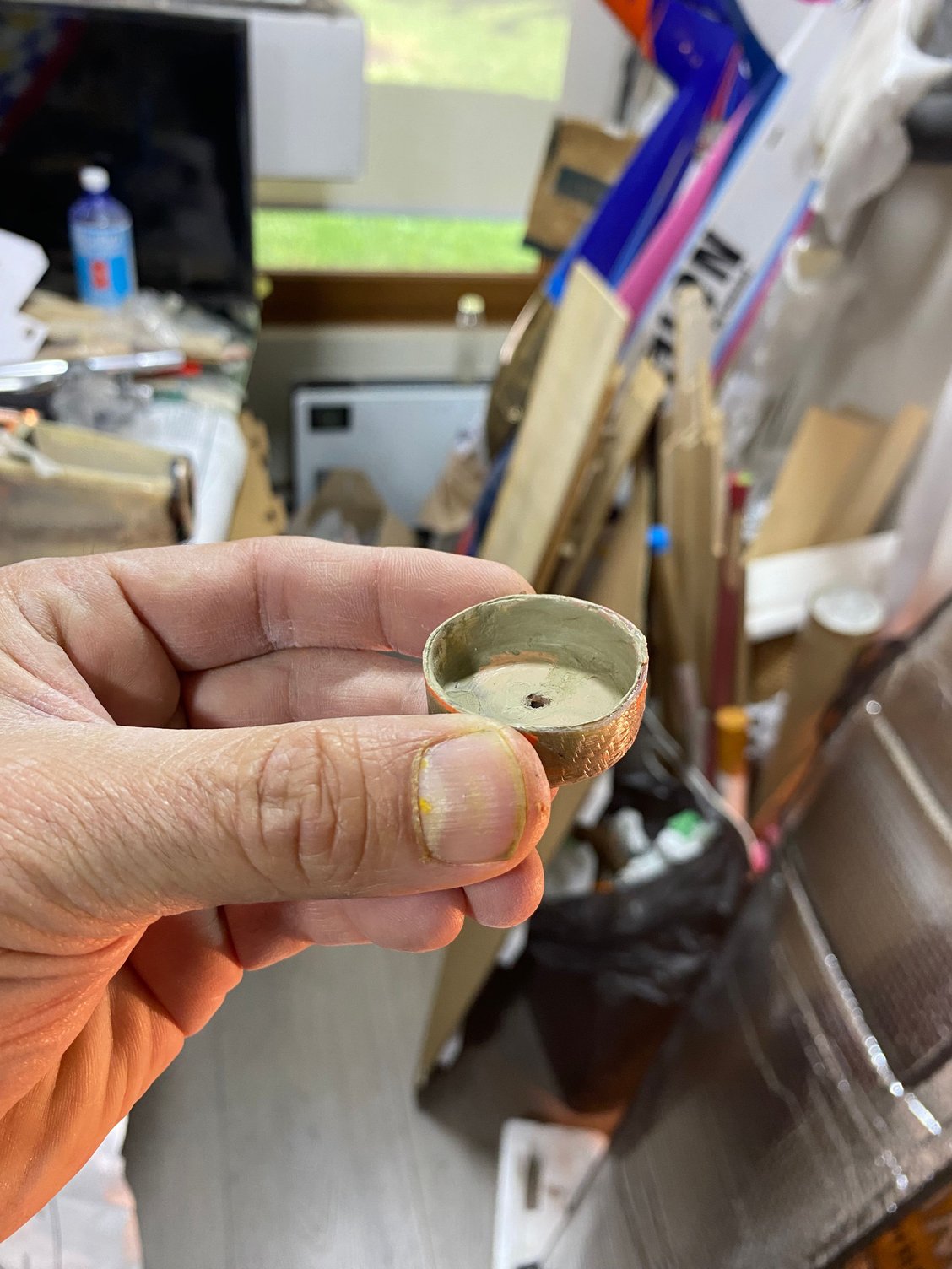
For ease of access, I opted to use a manually tightened knob instead of a bolt, selecting a nice 4 mm blue anodized threaded knob from AliExpress. To avoid having the knob protrude awkwardly from the belly pan, I added a recessed cylindrical pocket molded in fiberglass using a suitable cap as a mold. The recess was positioned and tack-glued in place with cyano. I later realized this may reduce the cooling airflow passage cross section, but is difficult to tell at this stage, so this will be evaluated and corrected if necessary during engine running; there is always room for going back...!
For the aft belly pan attachment, I used a plastic latch mechanism instead of the piano-wire system shown in the plans. A drilled hardwood block was bonded to the fuselage to support the latch mechanism.
This completed the belly pan attachment for the Aurora.
As shown in the photos, the lower front section of the fuselage has a built-in recess step of approximately 3 mm in the lower sidewall area, which secures the belly pan laterally. On the right side, I had to correct the fit by adding fiberglass putty to close a noticeable gap when fitting the belly pan, which required some additional work later at the finishing stages.
For the front attachment, I partially followed the method suggested in the plans, which uses an S-shaped metal beam bolted to the tank floor and to the belly pan. Instead, I used a 10 mm diameter carbon-fiber tube cut to the required height, with a 4 mm blind nut bonded inside.During horizontal positioning of this beam, care was taken to avoid interference with the nose retract (not yet in its final position) and the engine pipe header. As previously noted by someone, the nose retract on the Aurora—and on many designs of that era—is offset to one side (left) to clear the pipe header. However, it was still necessary to determine the correct offset to both meet this requirement and allow unobstructed operation of the steering arm assembly that was very close to the belly pan sidewall.
After trial-fitting all components, I determined that the retract mount needed to be positioned as far left as possible (viewed from the front) on the tank floor plate I had cut earlier. The carbon-fiber tube beam also needed to be slightly offset from the centerline. While this offset might have been avoided by using the metal S-beam, I still wanted to try this solution and considered the metal beam somewhat flimsy.
For ease of access, I opted to use a manually tightened knob instead of a bolt, selecting a nice 4 mm blue anodized threaded knob from AliExpress. To avoid having the knob protrude awkwardly from the belly pan, I added a recessed cylindrical pocket molded in fiberglass using a suitable cap as a mold. The recess was positioned and tack-glued in place with cyano. I later realized this may reduce the cooling airflow passage cross section, but is difficult to tell at this stage, so this will be evaluated and corrected if necessary during engine running; there is always room for going back...!
For the aft belly pan attachment, I used a plastic latch mechanism instead of the piano-wire system shown in the plans. A drilled hardwood block was bonded to the fuselage to support the latch mechanism.
This completed the belly pan attachment for the Aurora.
Last edited by Southern Flyer; 01-19-2026 at 04:08 PM.
03-28-2026 | 09:22 AM
#34
Hi all,
I haven’t updated the thread in a while, but the Aurora is now in its final stages. I’ll be posting some updated build photos in the next few posts.
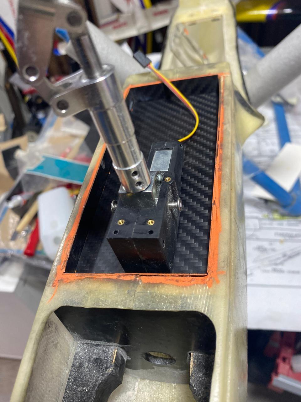
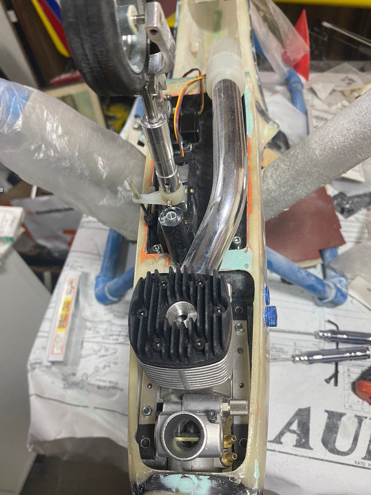
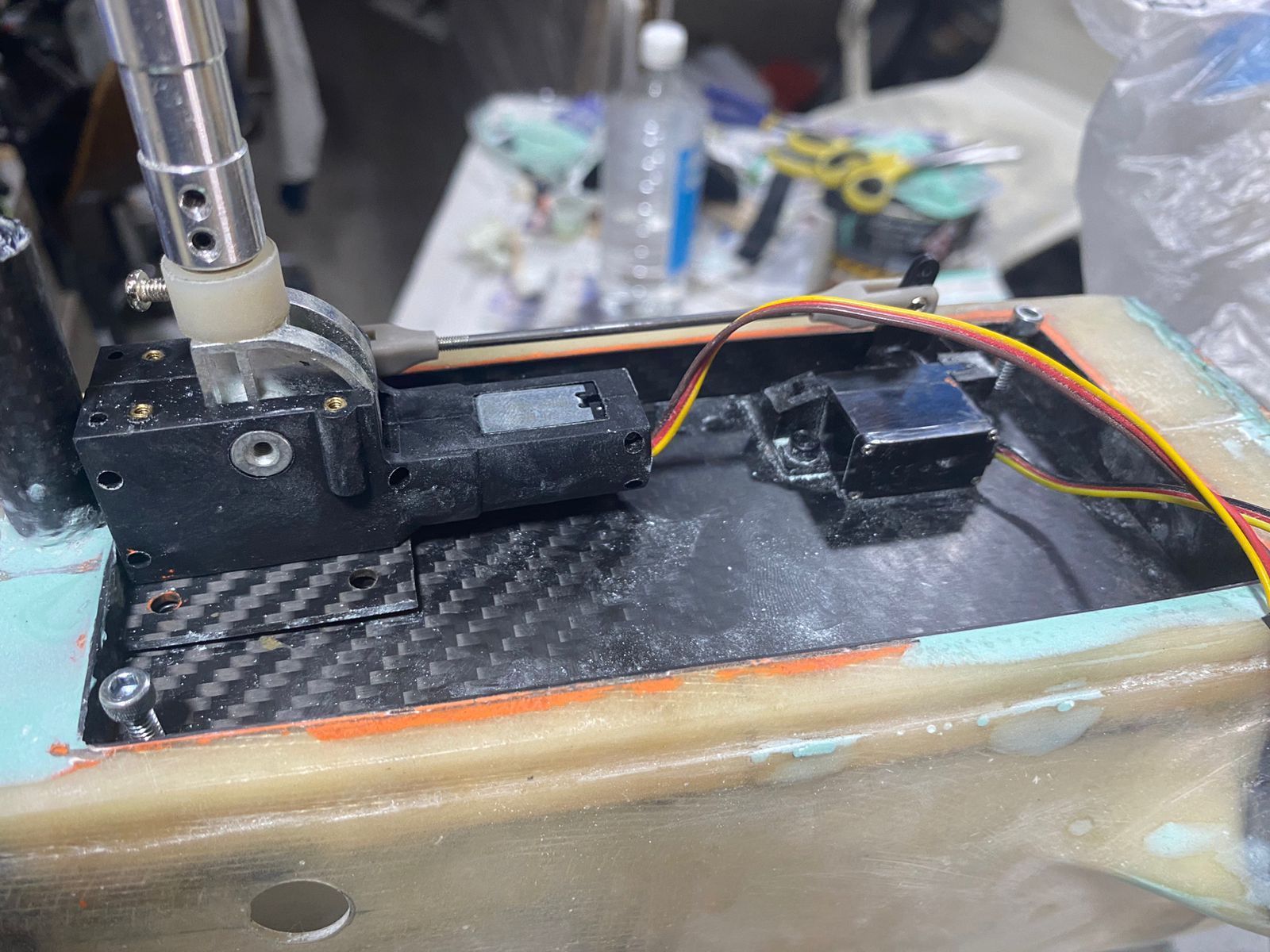
While trial-fitting the retract (mounted at one corner of the plate), I worked out the best position for the NG steering servo. In the end, mounting the servo sideways turned out to be the best solution, with the servo arm aligned directly with the retract steering arm.
I also had to swap out the steering arm that came with the retract for a much shorter one, to avoid it touching the belly pan wall.
With the servo mounted this way, I was able to get a perfectly straight pushrod—no bends or kinks at all, which is always nice.
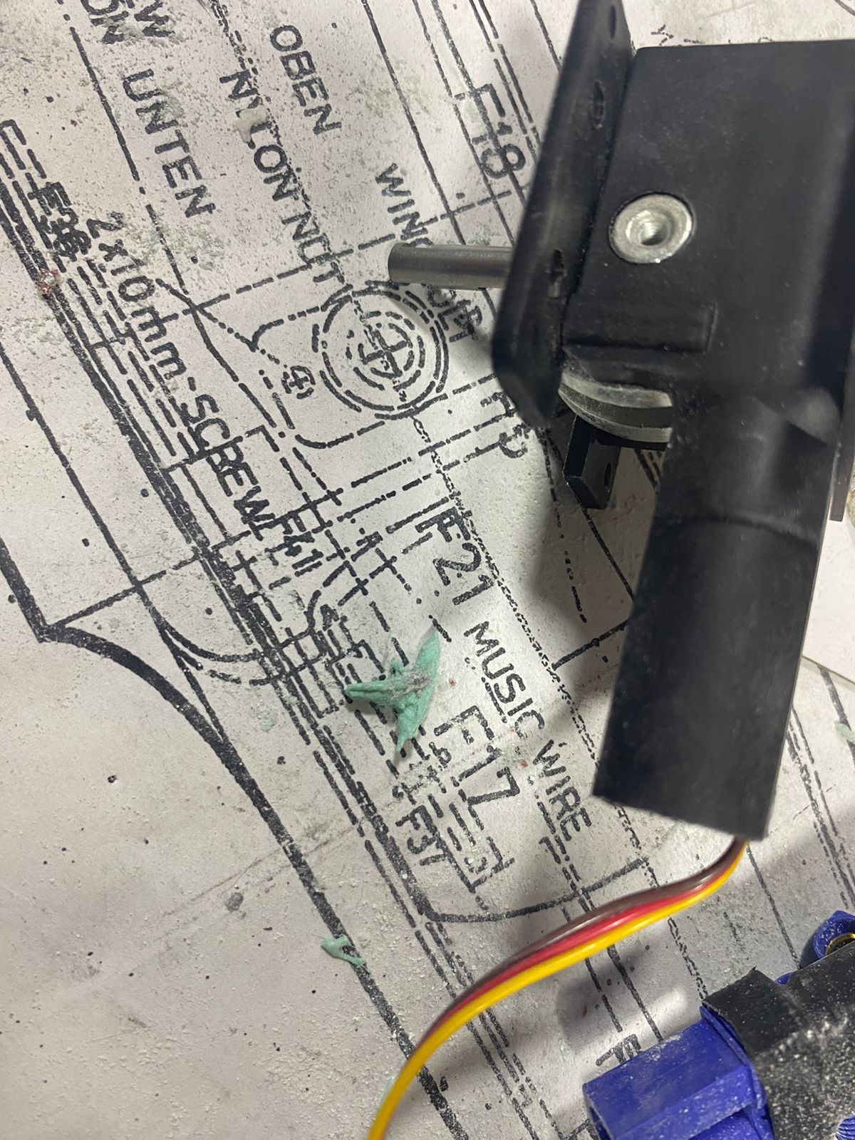
Another bonus: since I used a mini servo, when the strut is fully retracted it sits just above the servo case with no interference. You can see this in the photos below.


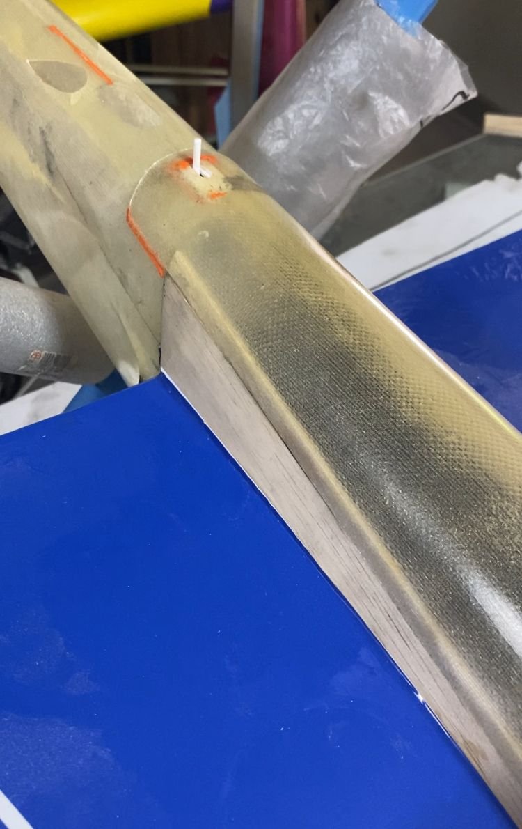
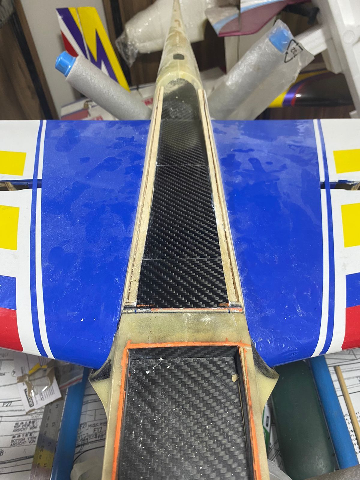
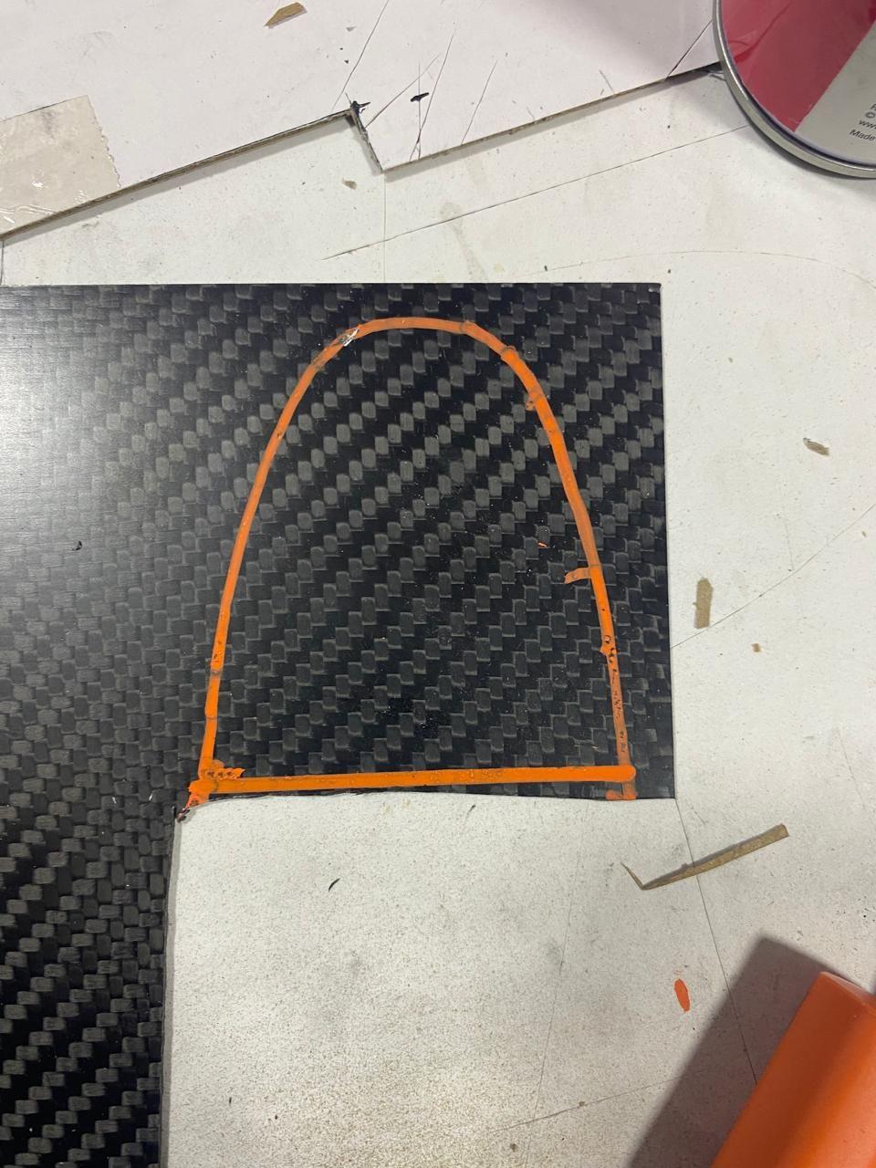
For the pipe tunnel, since I had already installed a carbon fiber plate as the tank floor, I decided to line the wing portion of the tunnel with a 0.2 mm carbon fiber sheet. It’s almost as thin as covering film, so the weight penalty is negligible, and it gives a clean look while also adding fuel-proofing.
The remaining work on the pipe tunnel included the exhaust outlet, cooling air exit openings, and the pipe exit cooling duct.


To maintain consistency with the carbon fiber finish, I made a two-angled CF deflector plate. I cut it to match the lower fuselage profile, glued it in place with rubber-toughened CA, and then reinforced it with some fiberglass cloth.

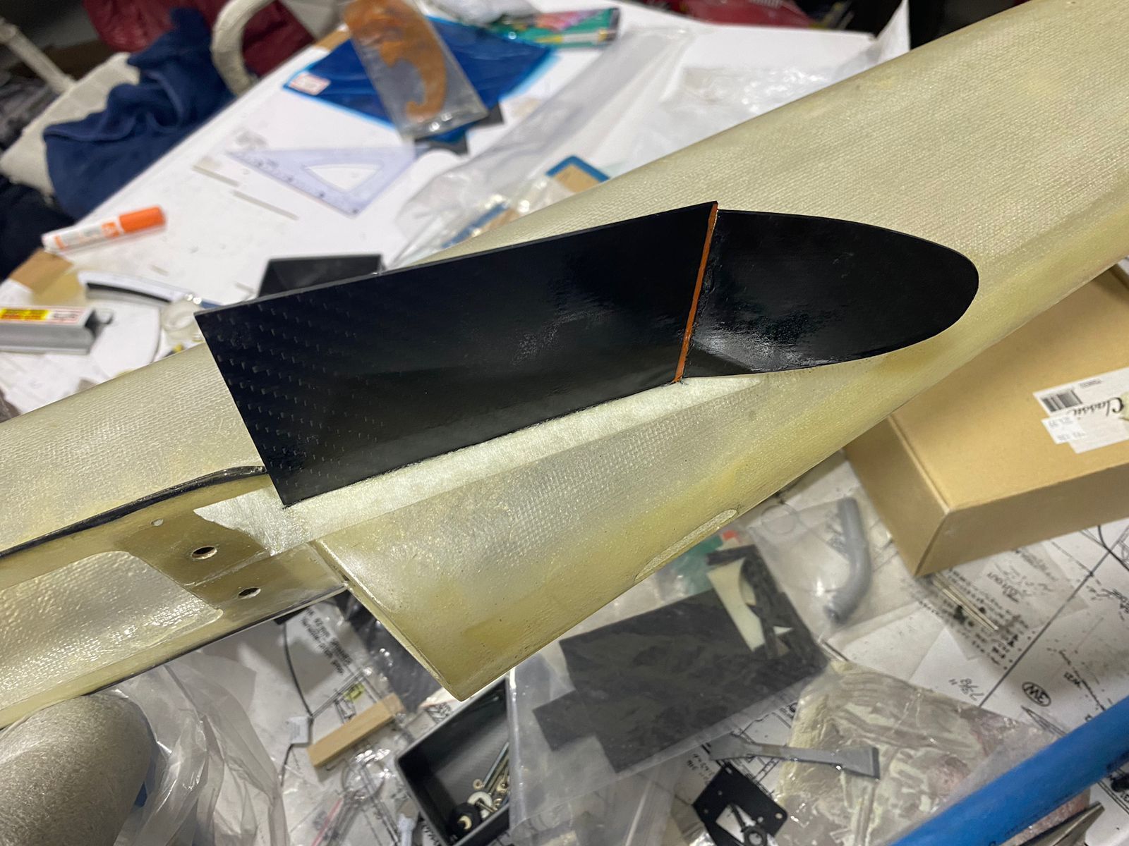
You can see how the finished pipe tunnel turned out in the photos.
I haven’t updated the thread in a while, but the Aurora is now in its final stages. I’ll be posting some updated build photos in the next few posts.
Back to the NG retract
Earlier I mentioned that the raised tank bottom plate—used as both the tank floor and nose retract mount—ended up bringing an extra benefit. This became clear when I started working on the nose retract steering linkage.While trial-fitting the retract (mounted at one corner of the plate), I worked out the best position for the NG steering servo. In the end, mounting the servo sideways turned out to be the best solution, with the servo arm aligned directly with the retract steering arm.
I also had to swap out the steering arm that came with the retract for a much shorter one, to avoid it touching the belly pan wall.
With the servo mounted this way, I was able to get a perfectly straight pushrod—no bends or kinks at all, which is always nice.
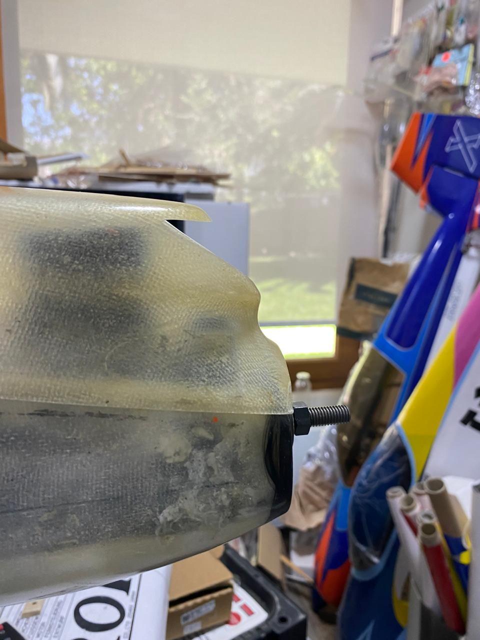
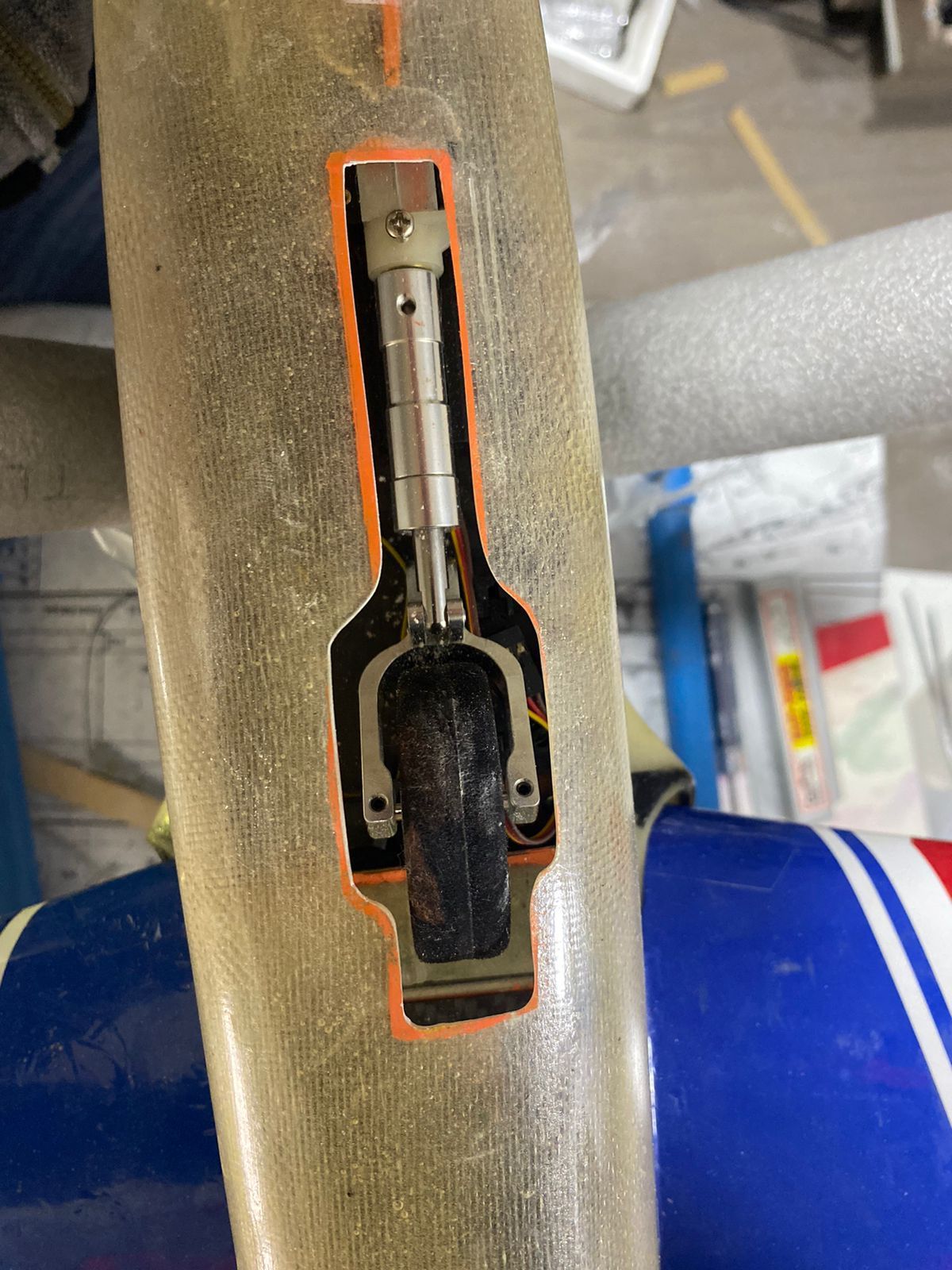
Another bonus: since I used a mini servo, when the strut is fully retracted it sits just above the servo case with no interference. You can see this in the photos below.

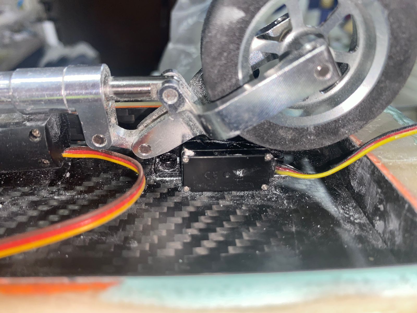
The NG strut rests flush to the steering servo
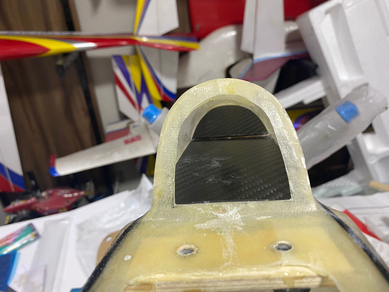
[size=13px]Next up was the engine cooling air intake. I tried to match the size and shape as closely as possible to the plans and to reference photos of the Aurora I found online.[/size]
For the pipe tunnel, since I had already installed a carbon fiber plate as the tank floor, I decided to line the wing portion of the tunnel with a 0.2 mm carbon fiber sheet. It’s almost as thin as covering film, so the weight penalty is negligible, and it gives a clean look while also adding fuel-proofing.
The remaining work on the pipe tunnel included the exhaust outlet, cooling air exit openings, and the pipe exit cooling duct.
To maintain consistency with the carbon fiber finish, I made a two-angled CF deflector plate. I cut it to match the lower fuselage profile, glued it in place with rubber-toughened CA, and then reinforced it with some fiberglass cloth.
You can see how the finished pipe tunnel turned out in the photos.
Last edited by Southern Flyer; 03-28-2026 at 09:29 AM.


