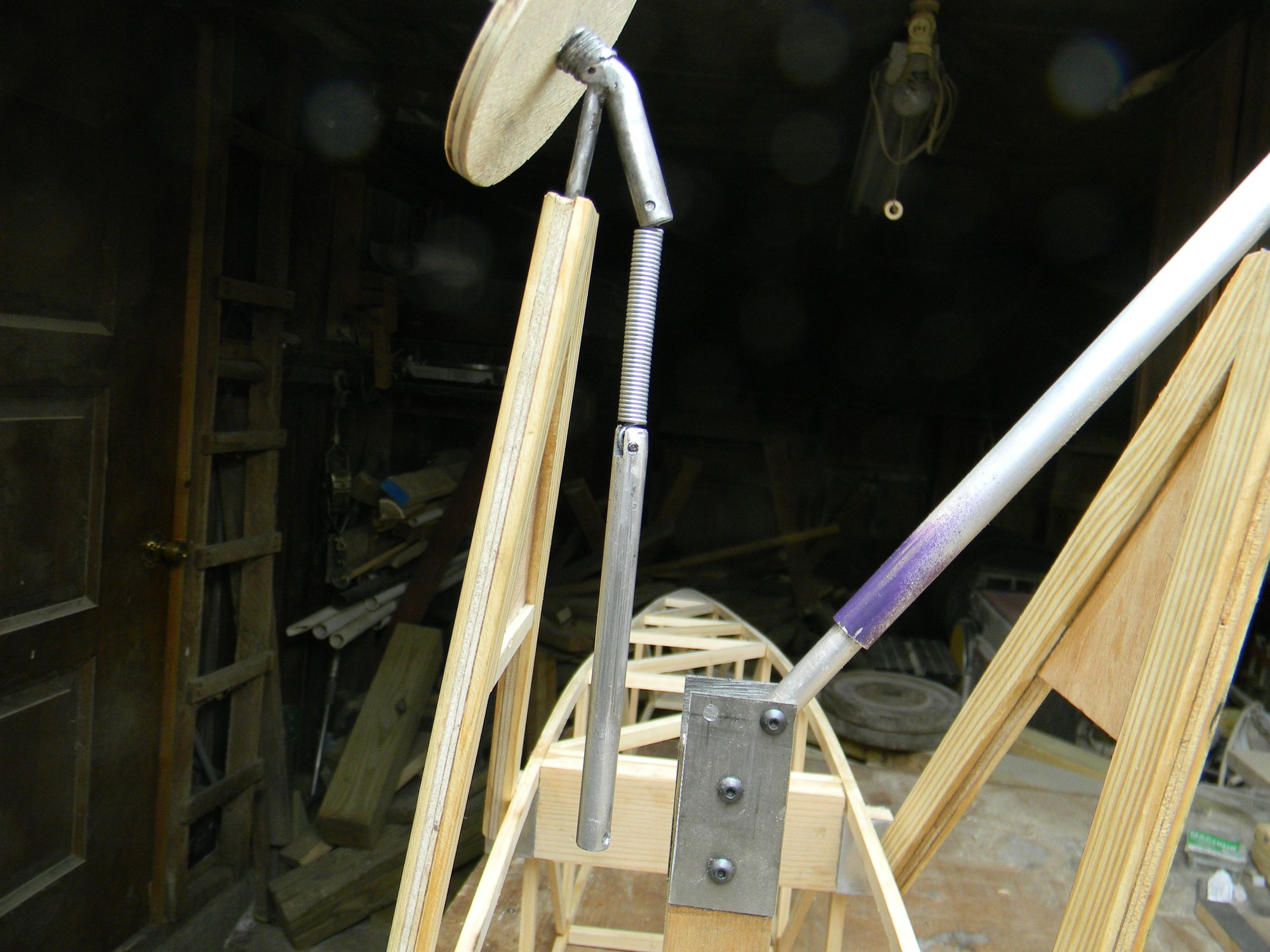
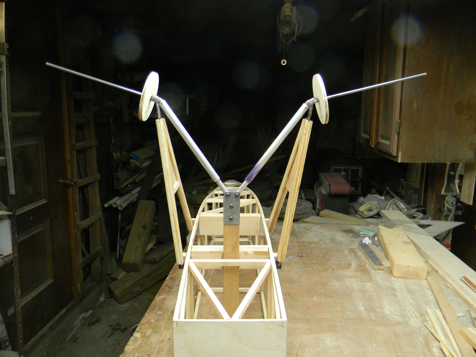
Landing gear is constructed of 3/16� steel rod with the addition of a 5/16� steel rod shock anchor point at the axle. The silver things are spring loaded shocks. Each leg was shaped separately with the axle integrated into the leading leg of the assembly. Legs are brazed together at the axle, shock anchor silver soldered to the axle.
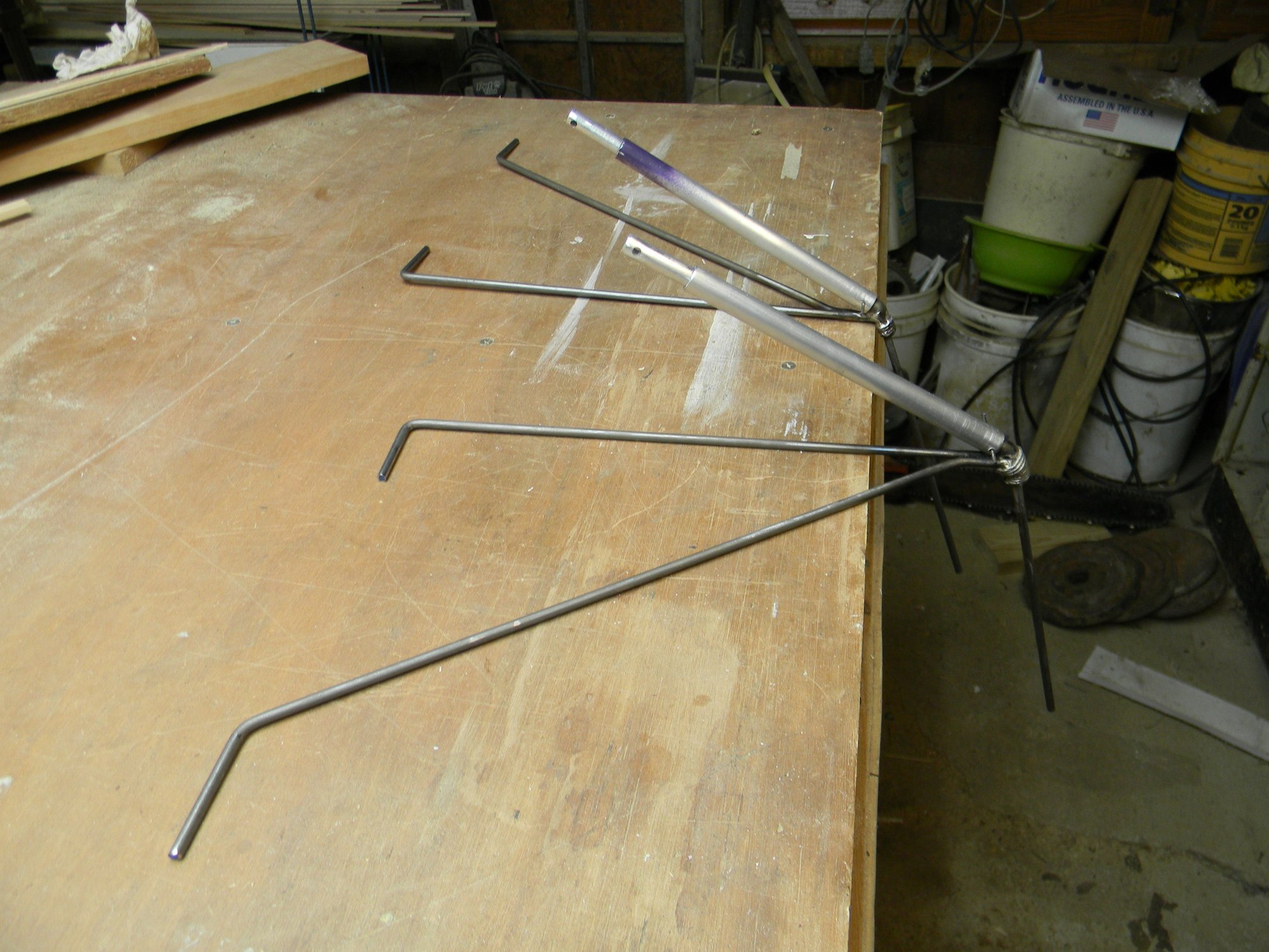
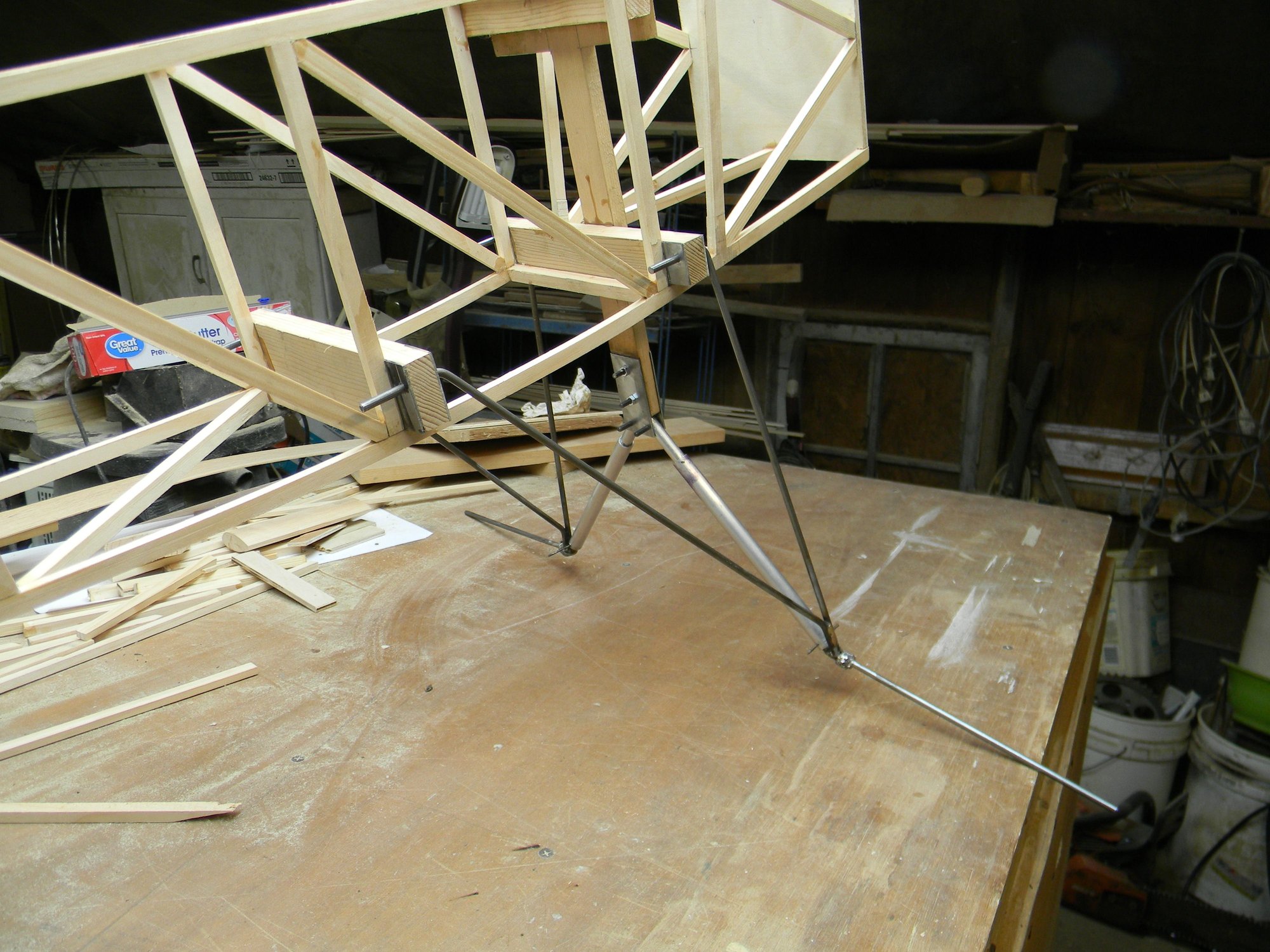
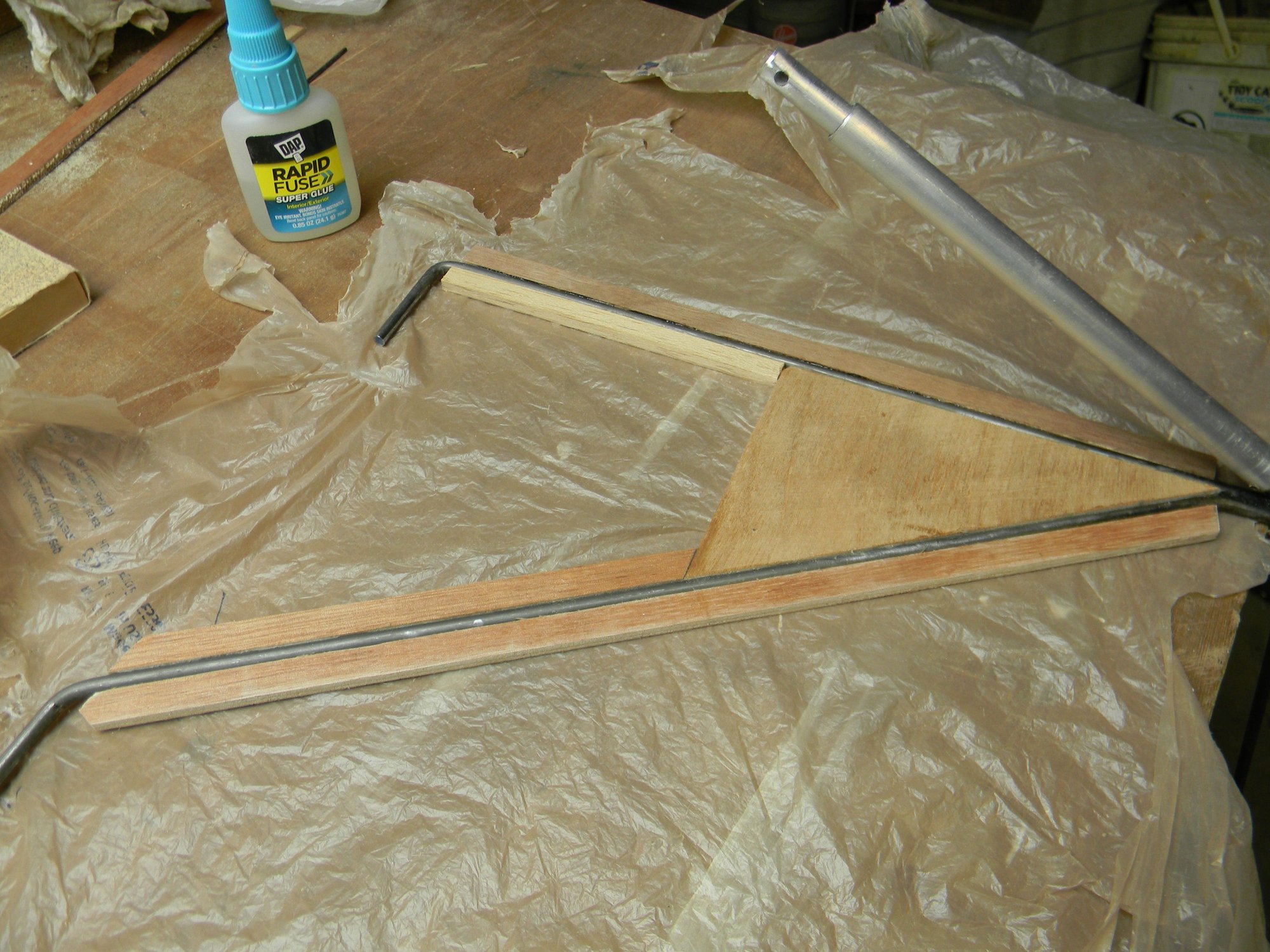
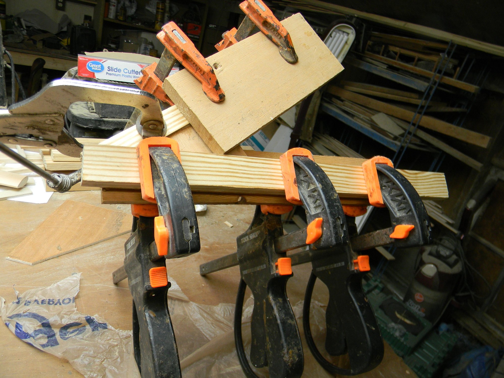
After fitting and testing, the �Y� part of the gear was fitted to light ply spacers held in place with medium thick CA then laminated between clear white pine strips. Each strut leg will later be given a streamlined airfoil type shape.
Each shock was fabricated using 3/8� aluminum tubing, 5/16� aluminum rod, a spring and two pins made from 1/16� drill rod. One end of the spring is pinned to the anchor at the axle, the other end pinned to the rod. The aluminum tube is held in place at the axle by a 4mm bolt. At the shock tower, the rod is held in place by a 5mm bolt. So, with the tube and spring anchored to the axle and the rod anchored to the tower, a rough approximation of a functioning oleo strut is created. The spring operates in tension to give the signature landing gear/wheel toe in while in the air and sized to provide typical appearance while on the ground while also providing shock absorption for that occasional hard landing.
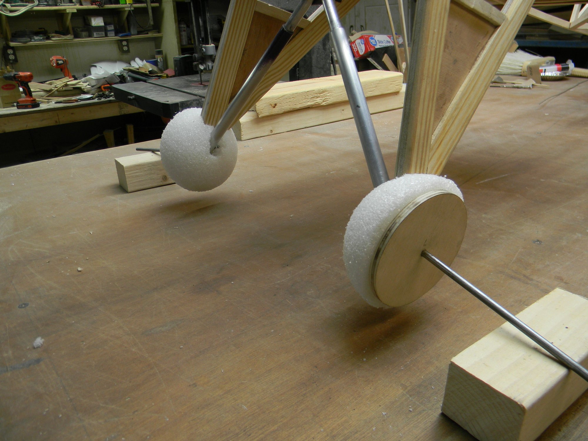
Styrofoam half rounds were glued to plywood discs to replicate the brake drum and fairing. Half rounds will later be given a teardrop shape as seen on the full size SBU brake drum fairing. Landing gear as pictured weighs 22.5 ounces bringing total weight to 45.5 ounces or roughly 2.8 pounds. Overall weight is well on target. So far.
Next posting we�ll have a look at building tail wheel gear.
Hank