


1/5 Scale SBU-1 Scratch Build
 03-14-2026 | 06:43 AM
#1
Thread Starter


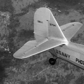
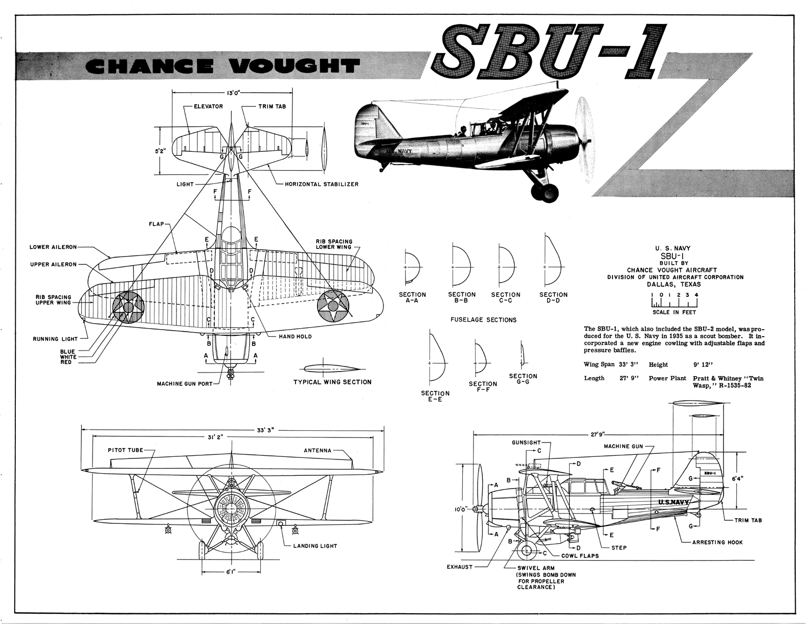
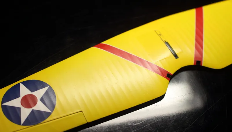
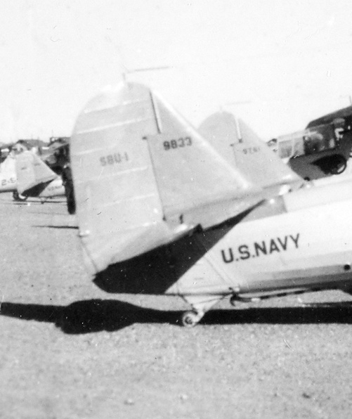
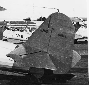
It’s been a couple decades since my last scratch build so I decided to start an SBU-1. I’ts a beautiful airplane imo and it’s one that sees undeserved modeling neglect. The pic is the one I’m attempting to replicate. It’s BurAer #9759 of VS-41 stationed onboard USS Ranger (CV-4) during the late 1930’s. Aside from the Lukgraph resin model, I’ve not seen any other example, RC or otherwise, of this interwar carrier based aircraft. It will be museum scale (80 inch wing span) and I have targeted the weight for 16 pounds or less. At 16 pounds the wing volume loading (WVL) is 7.9, which will result in an easy flying scale model. And, as always, less weight is better. Other than a Guillows SE-5 kit I’ve not built a biplane let alone one from scratch. It’s proving to be quite a challenge. I just hope to live long enough to finish it. Yes, I’m that old.
An SBU-1 rubber powered model plan by FSI is available on OZ as well as a three view available on the Vought website. The 3 view from Vought is not to scale but does give critical dimensions, which made scaling to 1/5 straightforward. The FSI plan contains several design inconsistencies but it does provide valuable info on details peculiar to the SBU-1. Nick Ziroli offers a 1/8 scale plan by Dick Katz but I’m too cheap the shell out $30 for it.
The fuse frame is already built along with the landing gear, tail wheel gear, empennage and cabane. I’ll be posting more pics and progress detail as time permits. Thanks for stopping by.
 03-14-2026 | 07:58 AM
#2

I'll be following.
03-16-2026 | 02:19 PM
#3
Thread Starter
Thanks Matt. My skills are a little rusty. Please let me know if you see something not quite right?
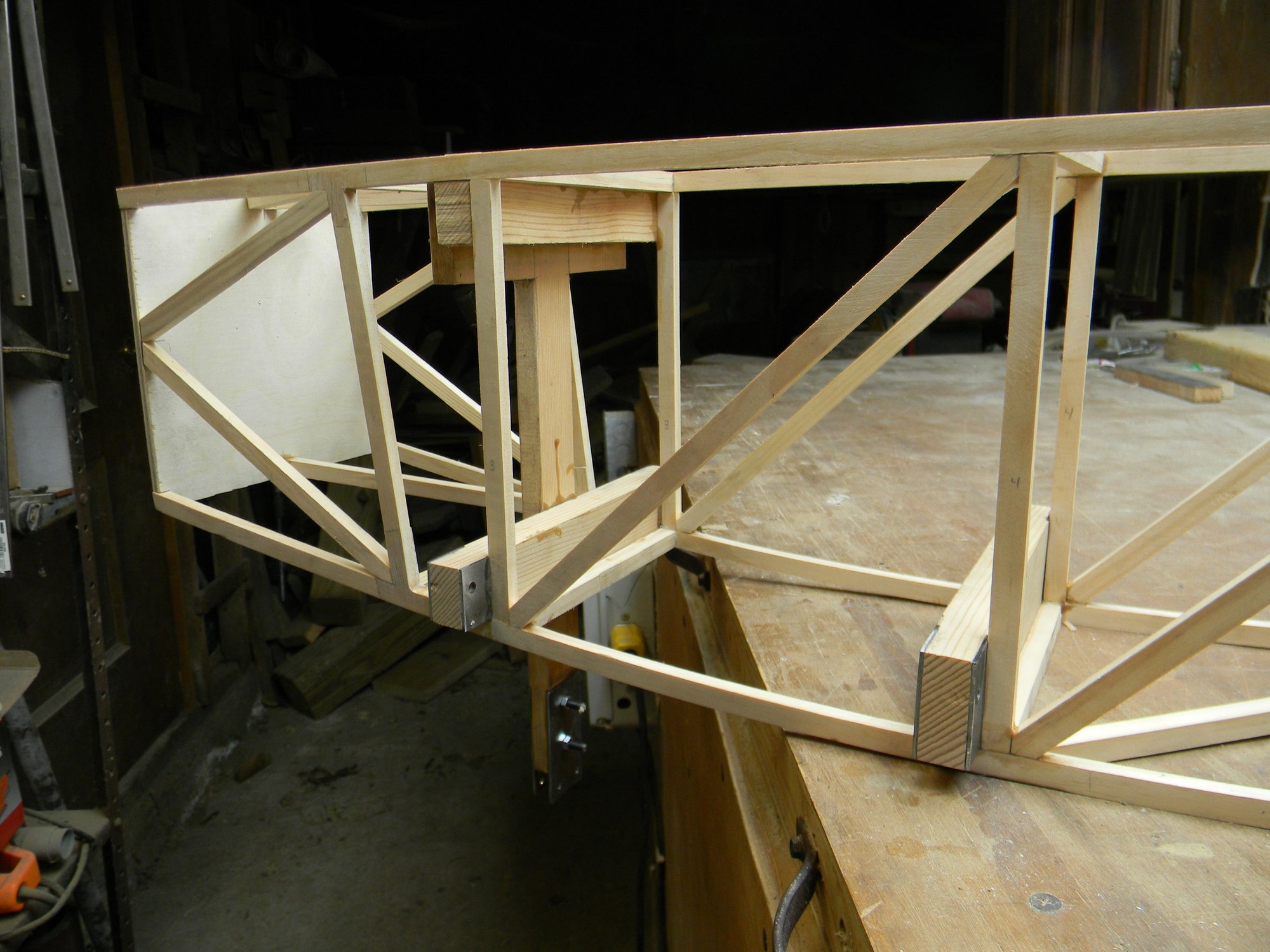
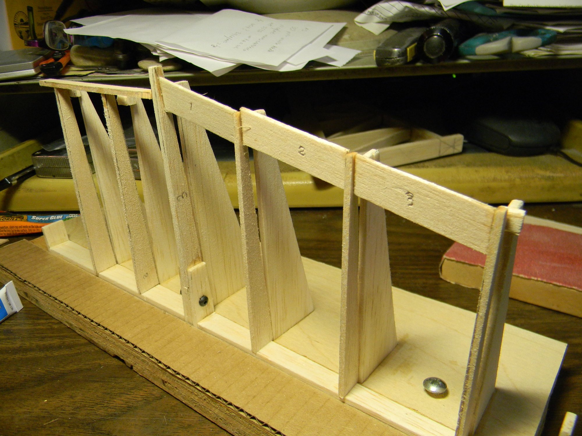
Spent a few days studying the FSI plan before drawing up the fuse frame plan in CAD. The first build attempt was a flop following the original FSI design. After making a few revisions, the fuse frame plan was printed out and a solid, workable frame was built. The material is clear, tightly grained white pine. Strips were ripped from a 6 foot x ľ” board then planed to 3/8” x 5/16”. The fame was built in customary manner over top of the plan one side at a time after cutting frame members to length. Joining the sides completed the assembly.
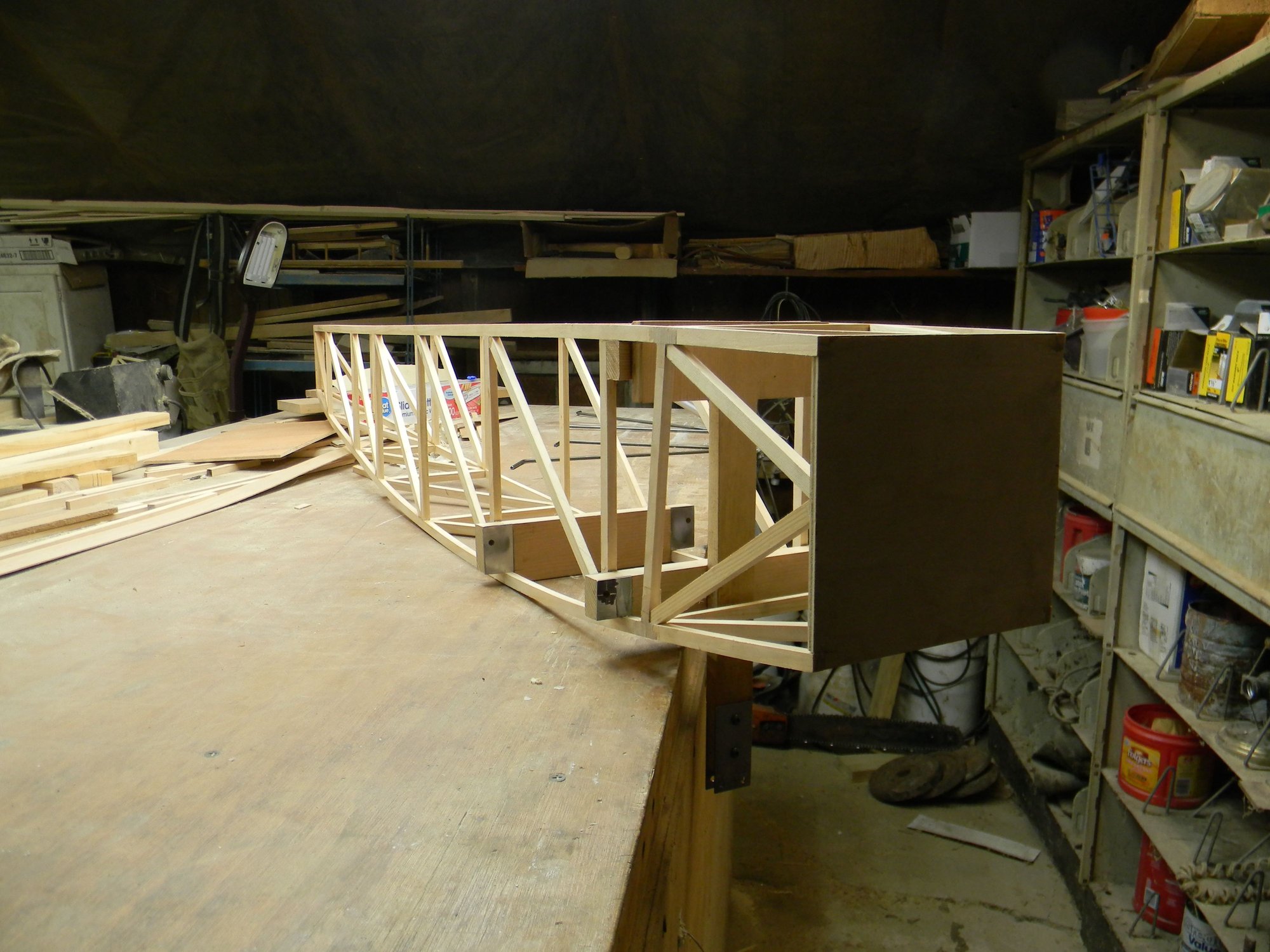
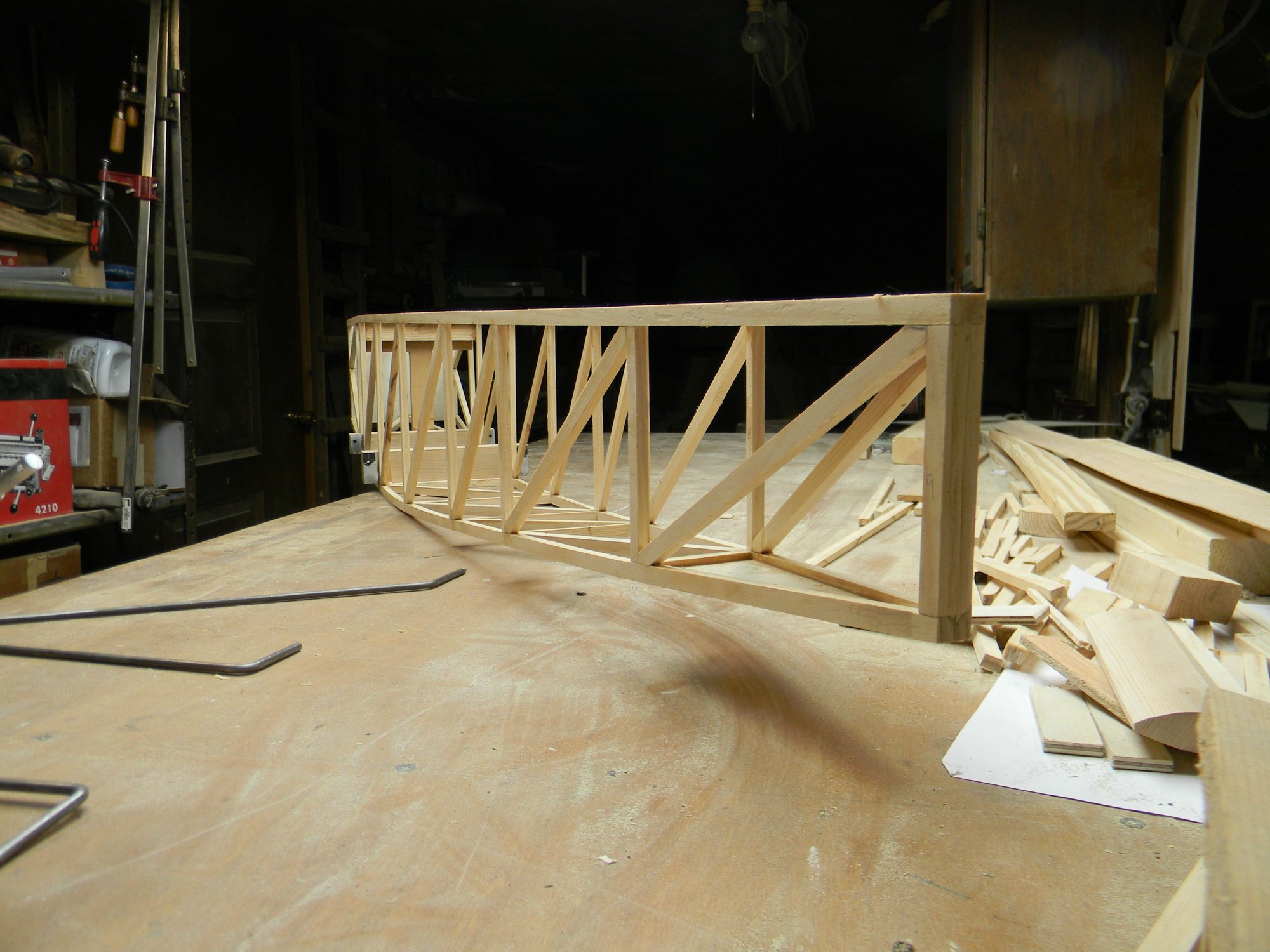
Landing gear strut anchors and shock tower is steel reinforced spruce epoxied to the frame. Frame weight is barely 23 ounces.
We’ll look at landing gear construction next. See you then.
Hank
Spent a few days studying the FSI plan before drawing up the fuse frame plan in CAD. The first build attempt was a flop following the original FSI design. After making a few revisions, the fuse frame plan was printed out and a solid, workable frame was built. The material is clear, tightly grained white pine. Strips were ripped from a 6 foot x ľ” board then planed to 3/8” x 5/16”. The fame was built in customary manner over top of the plan one side at a time after cutting frame members to length. Joining the sides completed the assembly.
Landing gear strut anchors and shock tower is steel reinforced spruce epoxied to the frame. Frame weight is barely 23 ounces.
We’ll look at landing gear construction next. See you then.
Hank
03-17-2026 | 07:51 AM
#5
I've often thought the FSI plans would be a good start for an RC plane. As for the plans from Ziroli, for what you are going to have tied up in an 80 inch model, I would think that $30 would constitute relatively cheap reference materials. Looks like you are off to a good start.
03-18-2026 | 01:35 AM
#7
Thread Starter
I've often thought the FSI plans would be a good start for an RC plane. As for the plans from Ziroli, for what you are going to have tied up in an 80 inch model, I would think that $30 would constitute relatively cheap reference materials. Looks like you are off to a good start.
Hank
03-18-2026 | 02:15 AM
#8
Thread Starter
Landing gear is constructed of 3/16” steel rod with the addition of a 5/16” steel rod shock anchor point at the axle. The silver things are spring loaded shocks. Each leg was shaped separately with the axle integrated into the leading leg of the assembly. Legs are brazed together at the axle, shock anchor silver soldered to the axle.
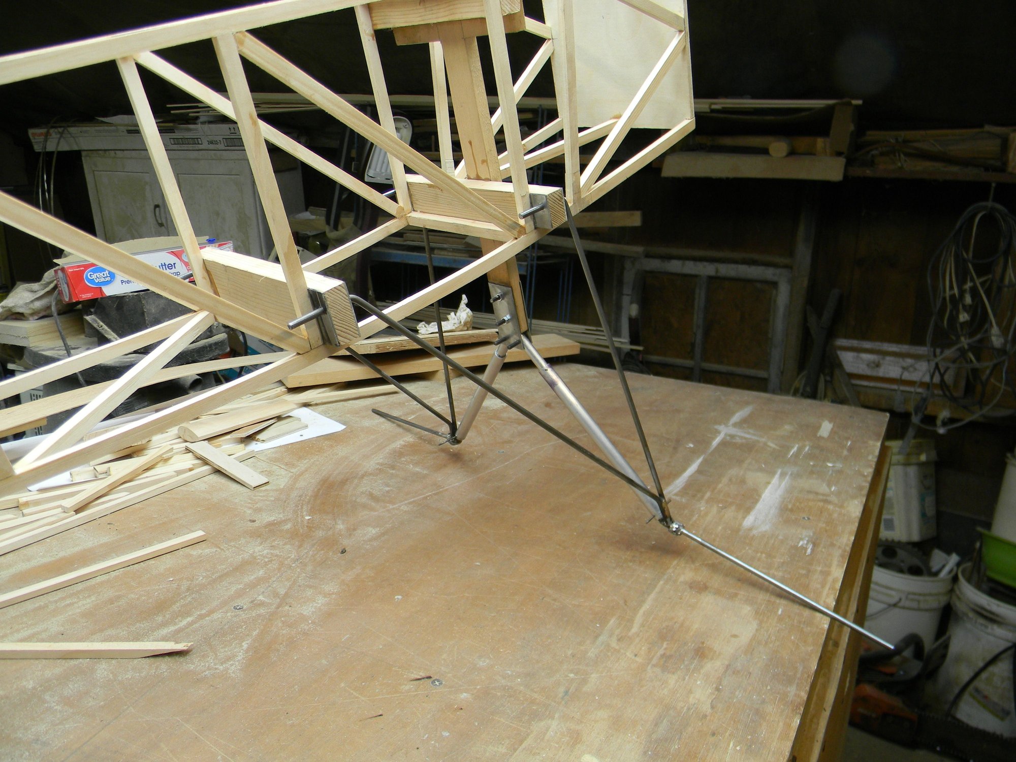
After fitting and testing, the “Y” part of the gear was fitted to light ply spacers held in place with medium thick CA then laminated between clear white pine strips. Each strut leg will later be given a streamlined airfoil type shape.
Each shock was fabricated using 3/8” aluminum tubing, 5/16” aluminum rod, a spring and two pins made from 1/16” drill rod. One end of the spring is pinned to the anchor at the axle, the other end pinned to the rod. The aluminum tube is held in place at the axle by a 4mm bolt. At the shock tower, the rod is held in place by a 5mm bolt. So, with the tube and spring anchored to the axle and the rod anchored to the tower, a rough approximation of a functioning oleo strut is created. The spring operates in tension to give the signature landing gear/wheel toe in while in the air and sized to provide typical appearance while on the ground while also providing shock absorption for that occasional hard landing.
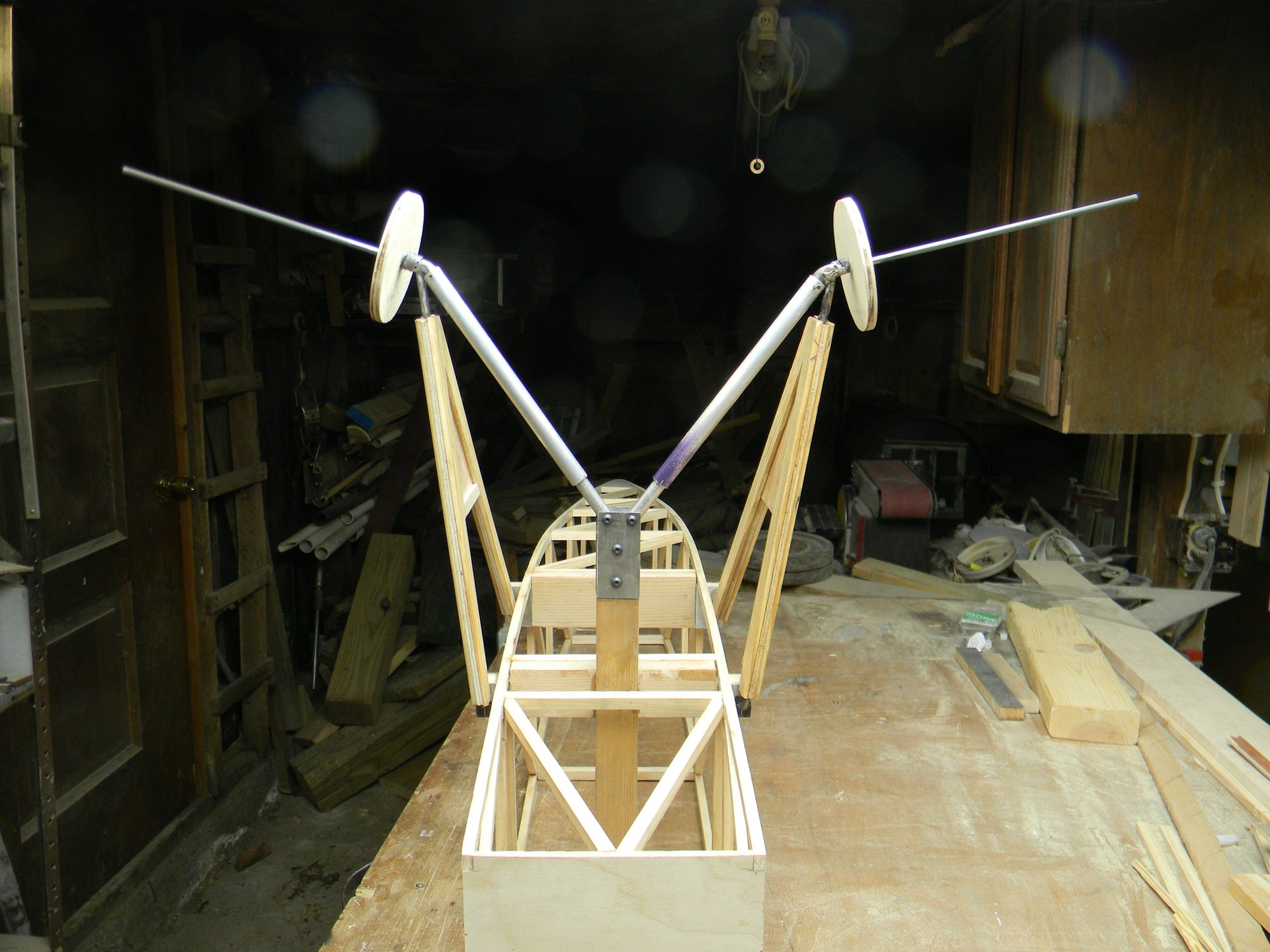
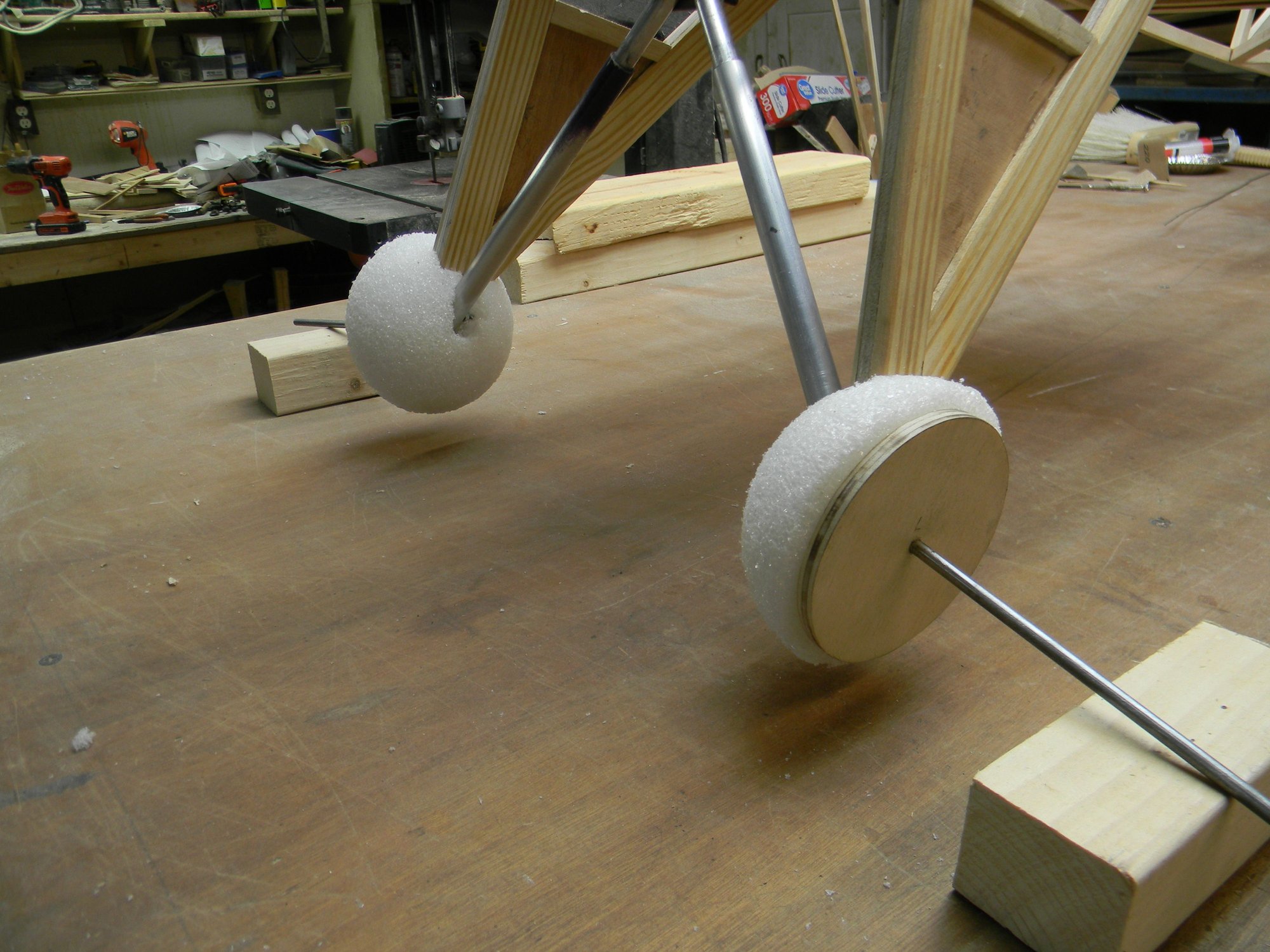
Styrofoam half rounds were glued to plywood discs to replicate the brake drum and fairing. Half rounds will later be given a teardrop shape as seen on the full size SBU brake drum fairing. Landing gear as pictured weighs 22.5 ounces bringing total weight to 45.5 ounces or roughly 2.8 pounds. Overall weight is well on target. So far.
Next posting we’ll have a look at building tail wheel gear.
Hank
After fitting and testing, the “Y” part of the gear was fitted to light ply spacers held in place with medium thick CA then laminated between clear white pine strips. Each strut leg will later be given a streamlined airfoil type shape.
Each shock was fabricated using 3/8” aluminum tubing, 5/16” aluminum rod, a spring and two pins made from 1/16” drill rod. One end of the spring is pinned to the anchor at the axle, the other end pinned to the rod. The aluminum tube is held in place at the axle by a 4mm bolt. At the shock tower, the rod is held in place by a 5mm bolt. So, with the tube and spring anchored to the axle and the rod anchored to the tower, a rough approximation of a functioning oleo strut is created. The spring operates in tension to give the signature landing gear/wheel toe in while in the air and sized to provide typical appearance while on the ground while also providing shock absorption for that occasional hard landing.
Styrofoam half rounds were glued to plywood discs to replicate the brake drum and fairing. Half rounds will later be given a teardrop shape as seen on the full size SBU brake drum fairing. Landing gear as pictured weighs 22.5 ounces bringing total weight to 45.5 ounces or roughly 2.8 pounds. Overall weight is well on target. So far.
Next posting we’ll have a look at building tail wheel gear.
Hank
03-18-2026 | 07:49 AM
#9
Those big ol' cross beams make sense now. I was wondering why such a stout structure. I like the DAP Rapid Fuse but It seems like I have to buy a new bottle anytime I start a new project. The shelf life is not great.
03-18-2026 | 01:37 PM
#10
Thread Starter
Yeah, the strut anchor beams are about twice as heavy as needed but i figured a little over engineering couldn't hurt that much weight wise. Not had a bottle of rapid fuse go bad. it's always used up before it has a chance to "spoil".
03-18-2026 | 01:58 PM
#11
Thread Starter
There’s two tail wheel sizes used on the SBU. It appears, at least to me, that land based SBU’s had a larger tail wheel while carrier based planes had a ridiculously small tail wheel. We're modeling a carrier based plane so a small tail wheel is in order. Since there’s no commercial offering for 1/5 scale SBU-1 tail wheel gear, we’ll build it from scratch. There’s four tail wheel gear requirements: it must be sturdy; tail wheel must be steerable; wheel gear must operate the rudder; the entire assembly must be adjustable for setup alignment.
Big tail wheel.
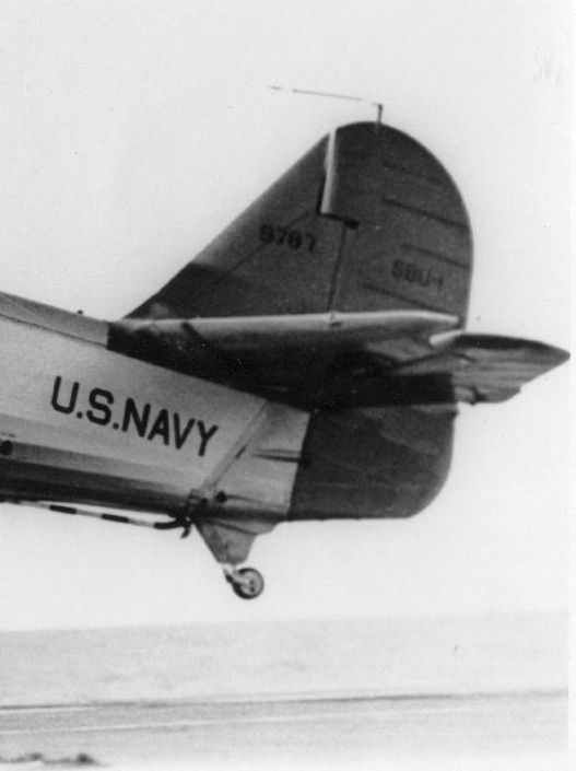
Small tail wheel.
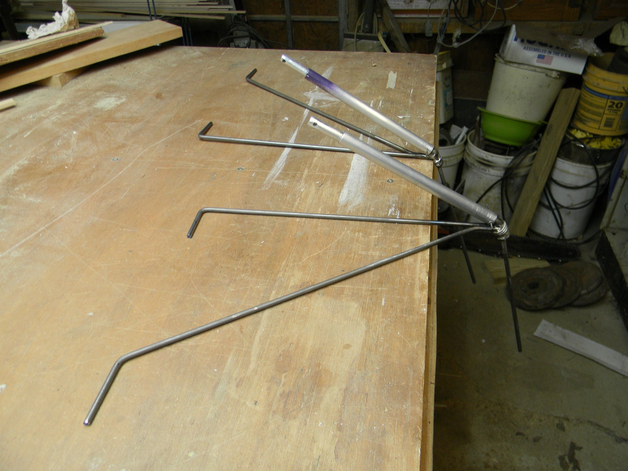
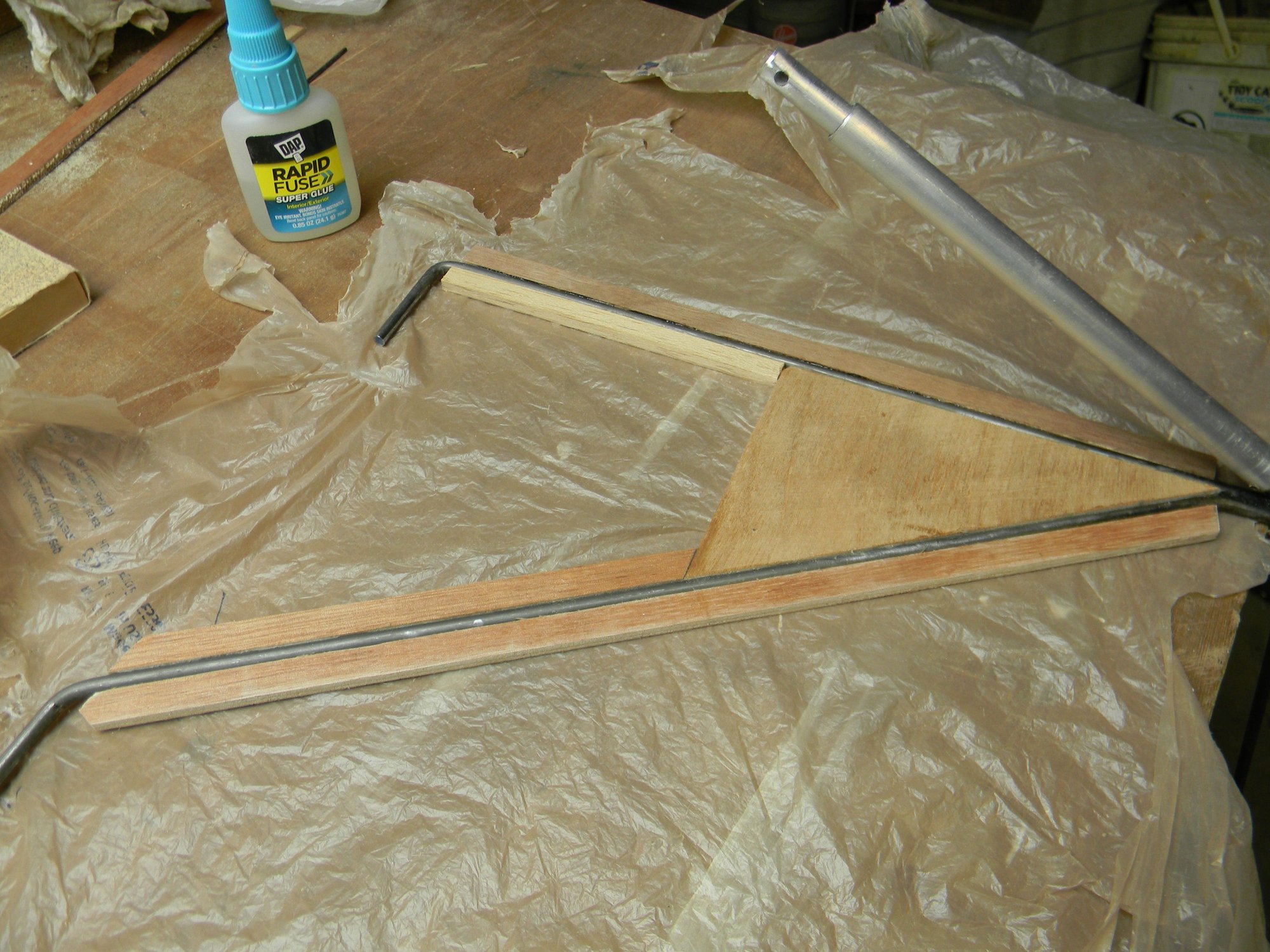
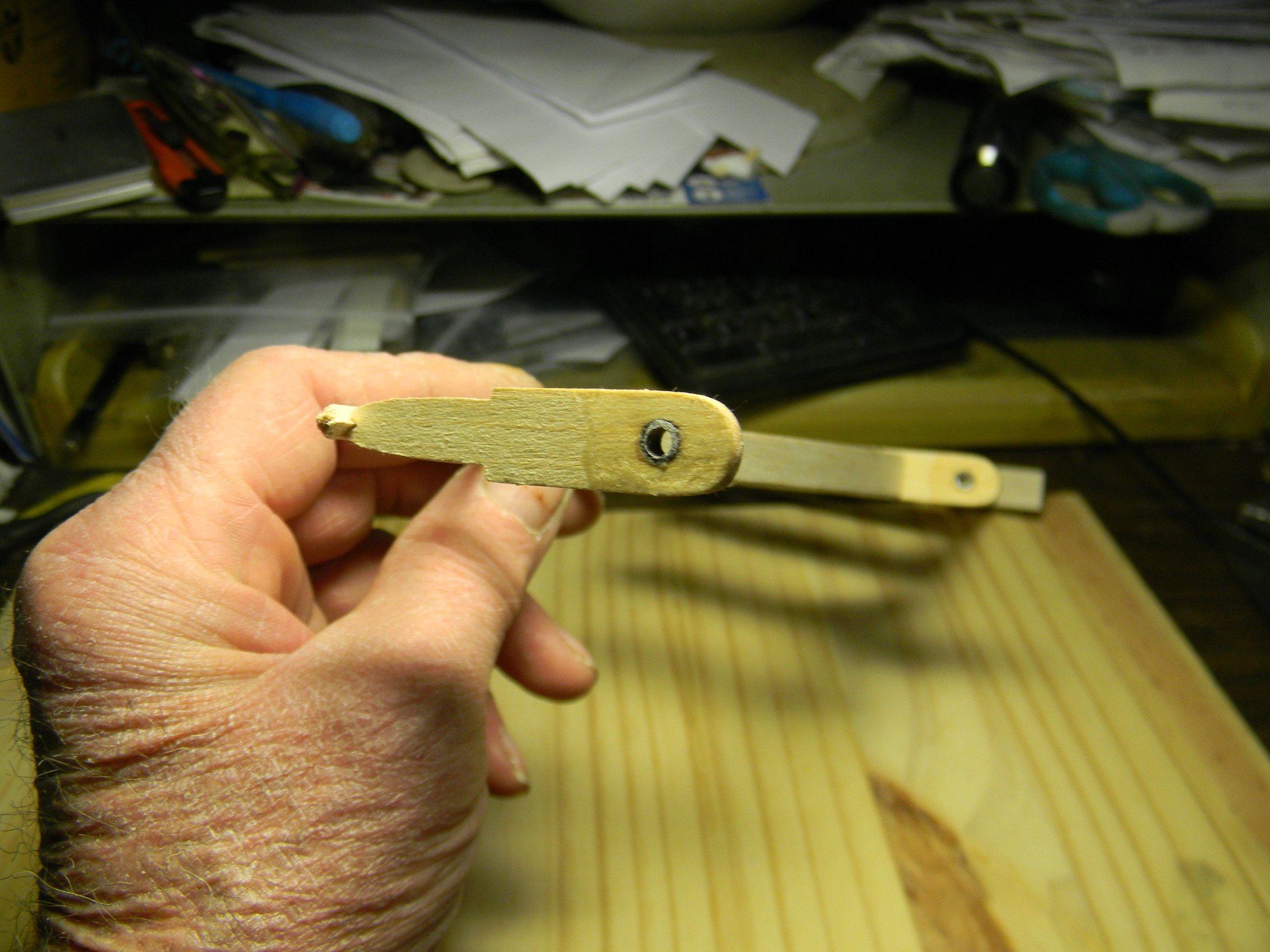
A tail wheel assembly was fabricated using ˝” steel rod, 3/16” steel rod and 16 gauge sheet metal. A Du-Bro 1” tail wheel and 2mm axle bolt completes the component list. Pic below is the raw material to fabricate the components.
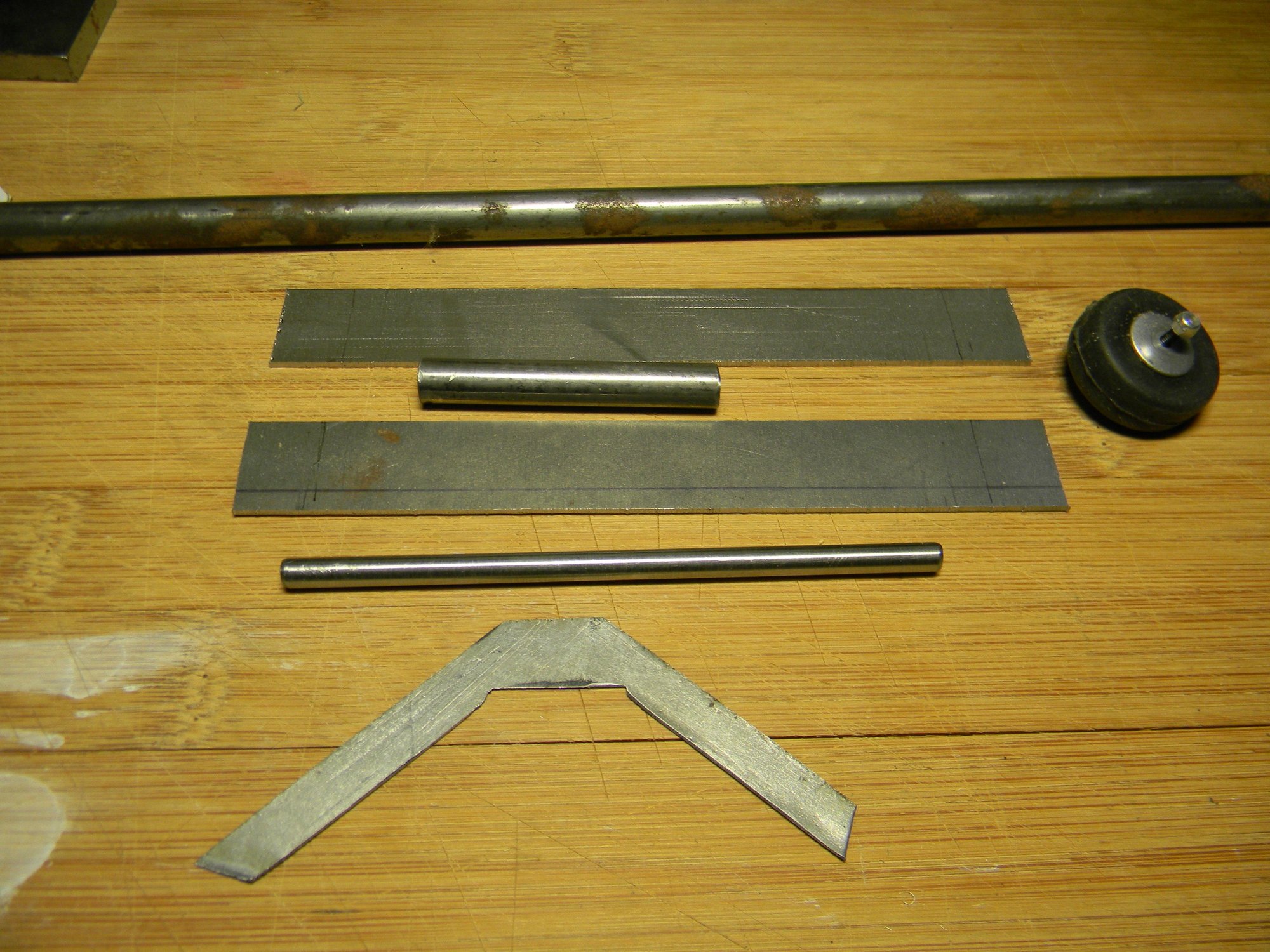
Raw goodies for a tail wheel assembly.
At the top of the pic is a rusty length of ˝” steel rod. One end of it was lathe turned to approximately 5/16” diameter then center drilled to accept a 3/16” rod. Cut from the turned portion is a 2” length to make the shaft bearing and two 3/8” lengths for control arm barrels. The shaft bearing is between the two longer pieces of sheet metal. After doing some layout work, gear mounting brackets (long pieces of sheet metal) was formed to shape and drilled for the shaft bearing. The tail wheel mounting yoke was then formed to shape and drilled for the 2mm axle bolt. A washer to act as a stop and the yoke was then silver soldered to the shaft. Below we have the completed components.
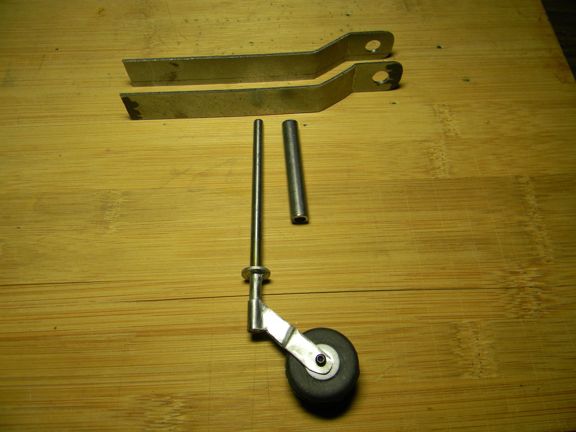
Fabricated components.
Pic below is a mock-up of how the gear fits to the fuse frame.
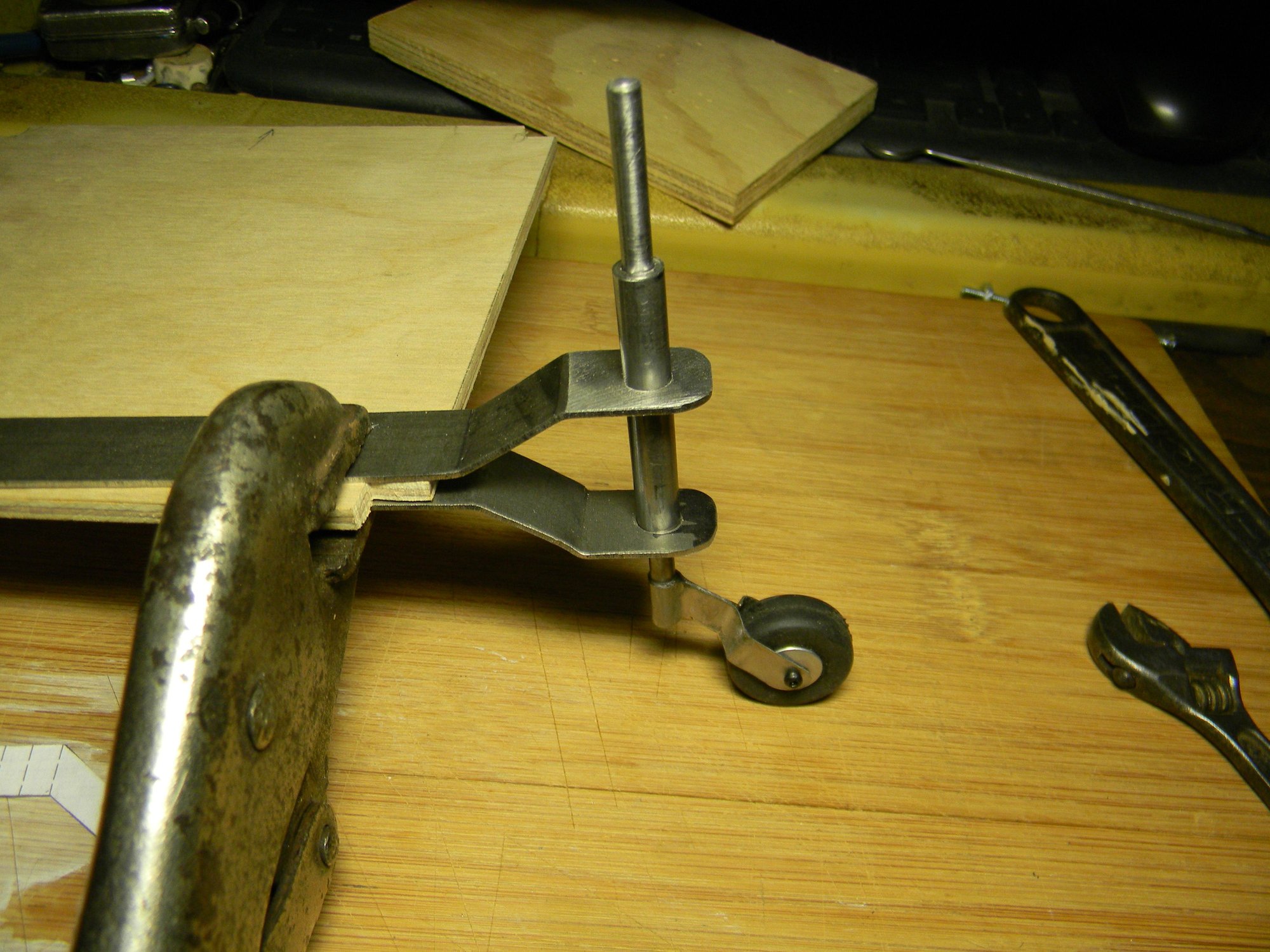
Mock up.
Two identical control arms fabricated from 16 gauge sheet metal along with the barrels mentioned above completes the tail wheel gear assembly. After shaping the wings of the arms and drilling for clevis pins, they were brazed to the barrels. The barrels were then drilled and tapped for 3/32” set screws, two on each barrel 180 degrees apart. The shaft bearing was silver soldered to the lower bracket after fitting to the fuse frame. Top bracket will be epoxied to the bearing after final fitting. Pic below shows the completed assembly.
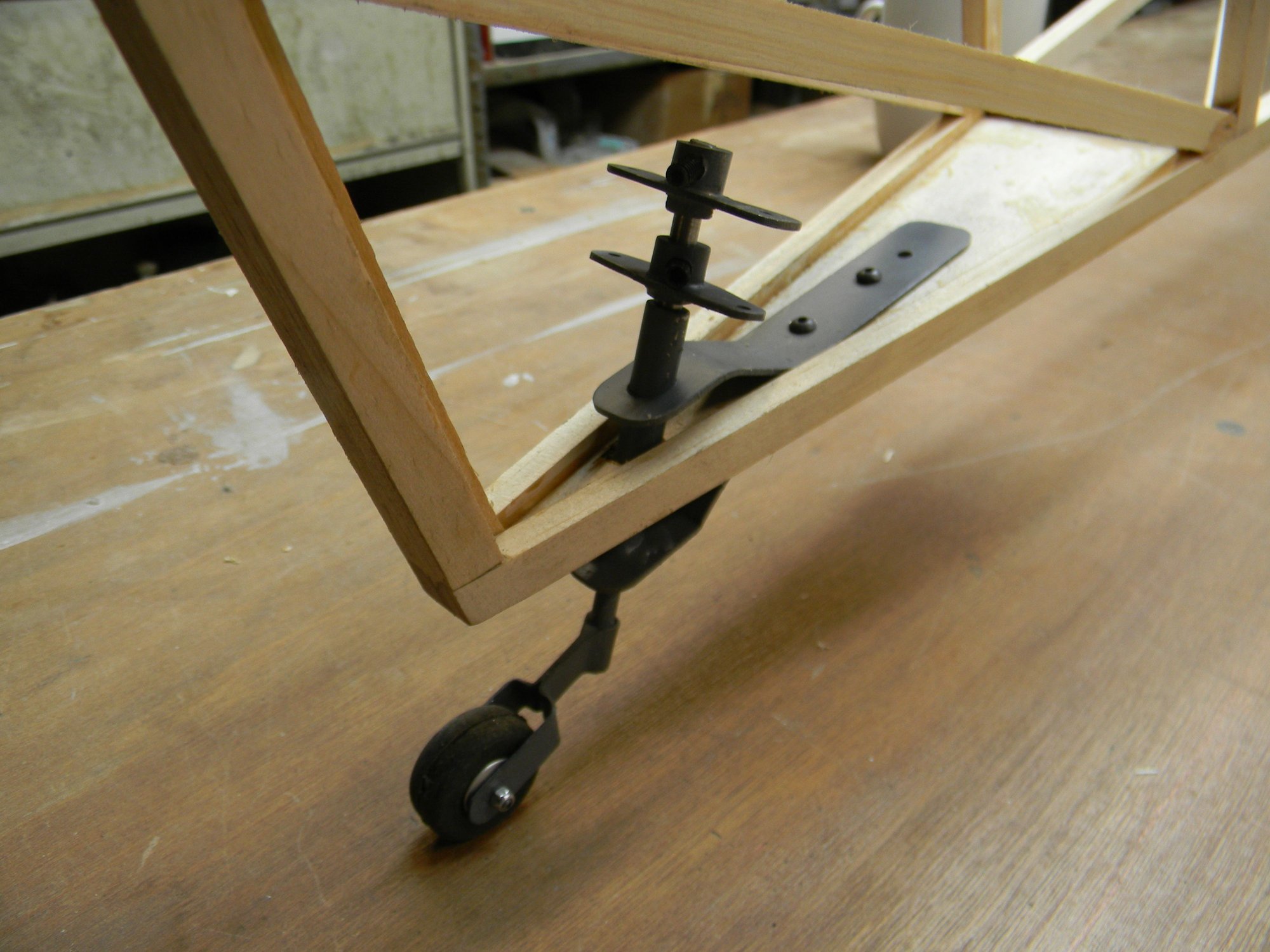
Completed tail wheel gear.
Top control arm connects to the servo via pull-pull cable. Bottom control arm connects to the rudder via push rods. Does this assembly meet all of the requirements? It is quite sturdy. The tail wheel is steerable. It will operate the rudder. And, it’s completely adjustable. In fact, angle of the tail wheel gear may require adjustment to more vertical while installing the pull-pull cable. We’ll see. And yes, we’ll use screw glue (locktite) on the set screws after everything is in alignment and adjusted accordingly. So there you have it- scratch built tail wheel gear from start to finish.
Next we’ll take a look at building the cabane. See you then.
Hank
Big tail wheel.
Small tail wheel.
A tail wheel assembly was fabricated using ˝” steel rod, 3/16” steel rod and 16 gauge sheet metal. A Du-Bro 1” tail wheel and 2mm axle bolt completes the component list. Pic below is the raw material to fabricate the components.
Raw goodies for a tail wheel assembly.
At the top of the pic is a rusty length of ˝” steel rod. One end of it was lathe turned to approximately 5/16” diameter then center drilled to accept a 3/16” rod. Cut from the turned portion is a 2” length to make the shaft bearing and two 3/8” lengths for control arm barrels. The shaft bearing is between the two longer pieces of sheet metal. After doing some layout work, gear mounting brackets (long pieces of sheet metal) was formed to shape and drilled for the shaft bearing. The tail wheel mounting yoke was then formed to shape and drilled for the 2mm axle bolt. A washer to act as a stop and the yoke was then silver soldered to the shaft. Below we have the completed components.
Fabricated components.
Pic below is a mock-up of how the gear fits to the fuse frame.
Mock up.
Two identical control arms fabricated from 16 gauge sheet metal along with the barrels mentioned above completes the tail wheel gear assembly. After shaping the wings of the arms and drilling for clevis pins, they were brazed to the barrels. The barrels were then drilled and tapped for 3/32” set screws, two on each barrel 180 degrees apart. The shaft bearing was silver soldered to the lower bracket after fitting to the fuse frame. Top bracket will be epoxied to the bearing after final fitting. Pic below shows the completed assembly.
Completed tail wheel gear.
Top control arm connects to the servo via pull-pull cable. Bottom control arm connects to the rudder via push rods. Does this assembly meet all of the requirements? It is quite sturdy. The tail wheel is steerable. It will operate the rudder. And, it’s completely adjustable. In fact, angle of the tail wheel gear may require adjustment to more vertical while installing the pull-pull cable. We’ll see. And yes, we’ll use screw glue (locktite) on the set screws after everything is in alignment and adjusted accordingly. So there you have it- scratch built tail wheel gear from start to finish.
Next we’ll take a look at building the cabane. See you then.
Hank
03-20-2026 | 03:03 AM
#12
Thread Starter
Building the cabane proved a bit more challenging than anticipated. The stumbling block was the amount of taper and airfoil trailing edge shape toward the center where hand holds are located as shown in the top wing in the 3 view drawing. The deep radius at the center of the cabane complicated the matter.
Every pic studied shows consistent taper from the center rib out to make the radius but the airfoil shape at the trailing edge is not consistent to NACA CYH data at the deepest point of the radius. I found the clearest image of this is a Lukgraph model built by Jan_G posted on largescaleplanes.com:
After spending days trying to figure this out I finally decided to forget about the actual CYH airfoil trailing edge datum and freehand the trailing edge of the center ribs using CAD. Once that was settled it became a simple matter of generating the remaining rib profiles, printing the patterns and building the ribs.
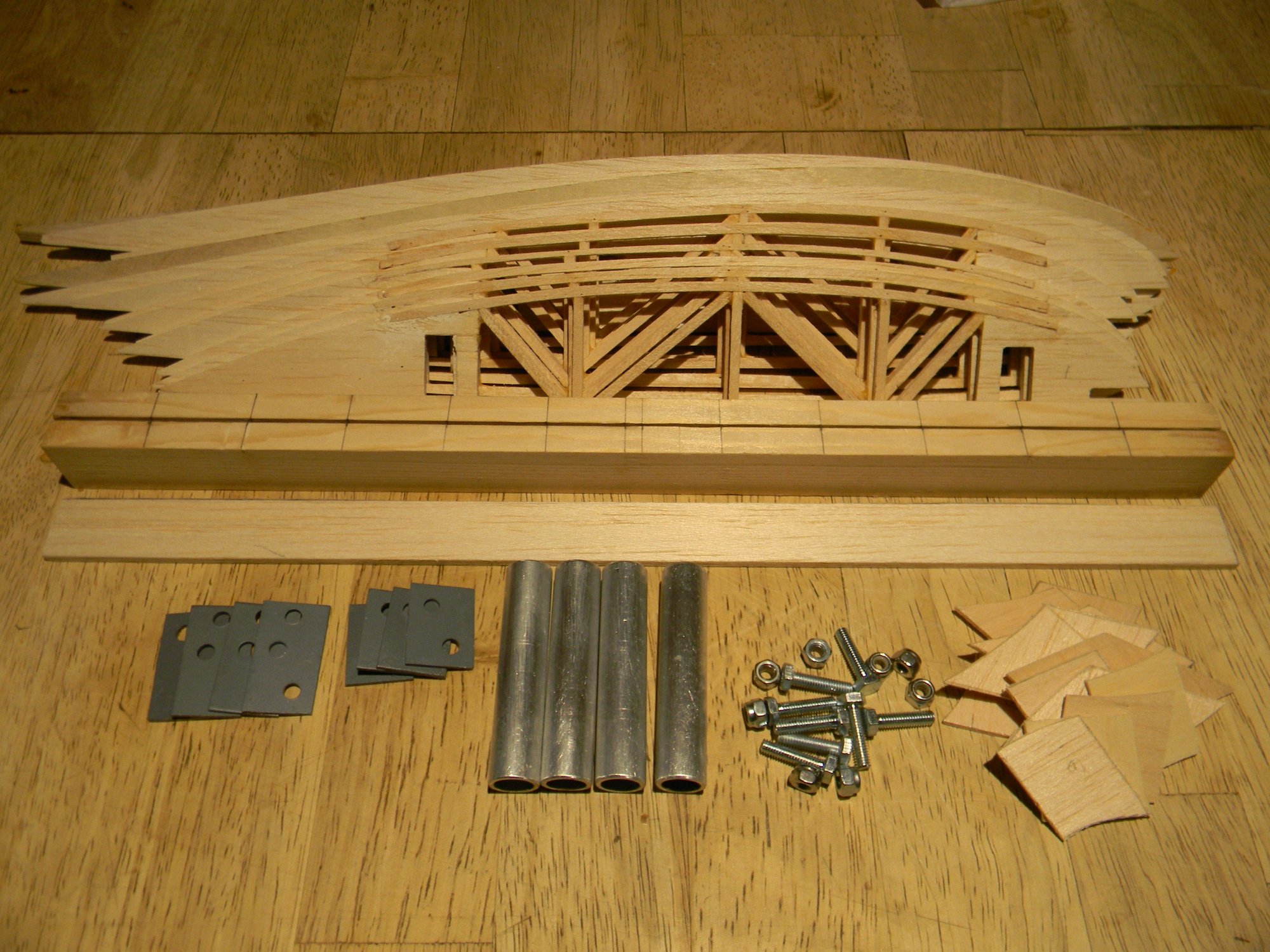
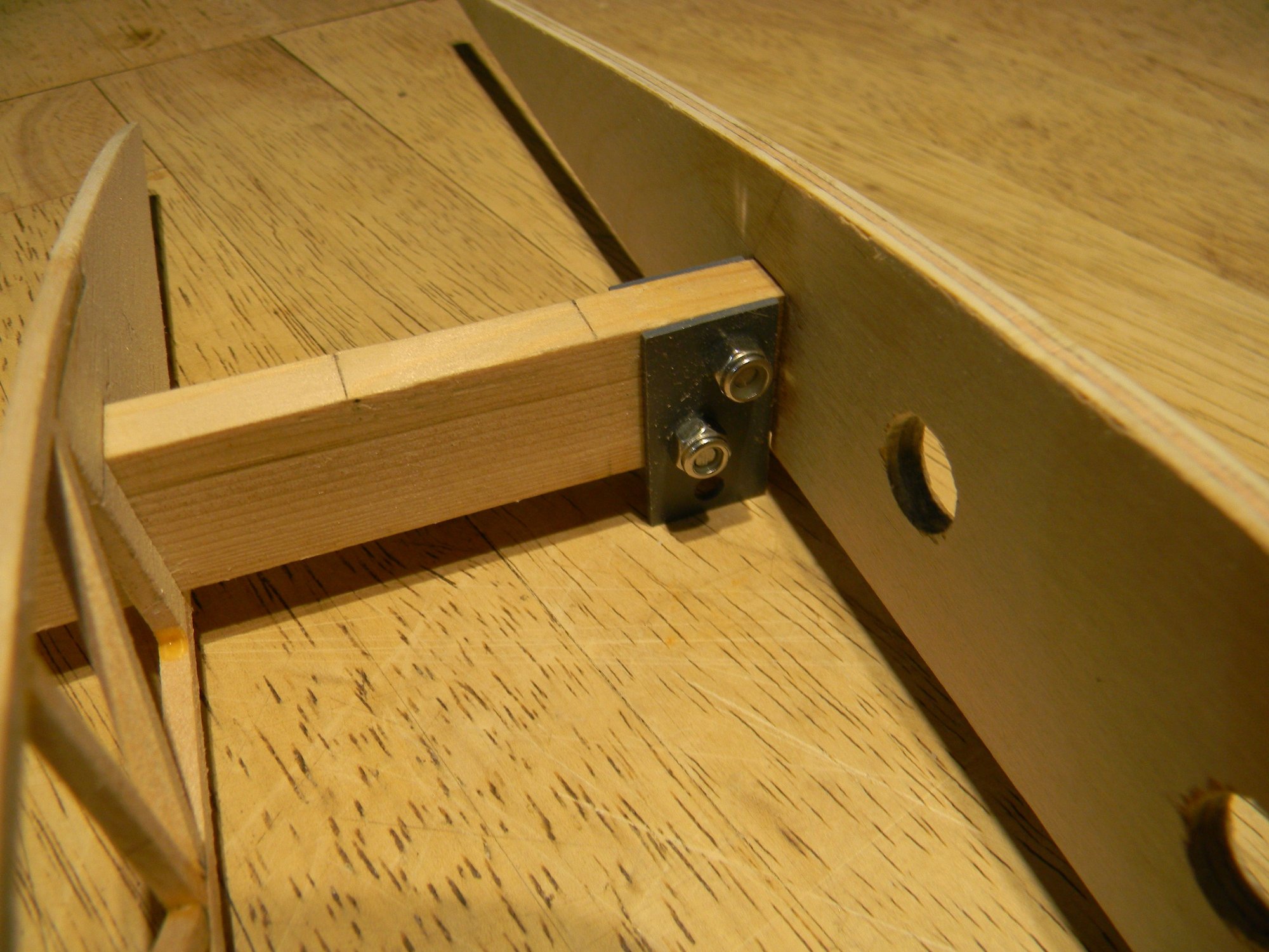
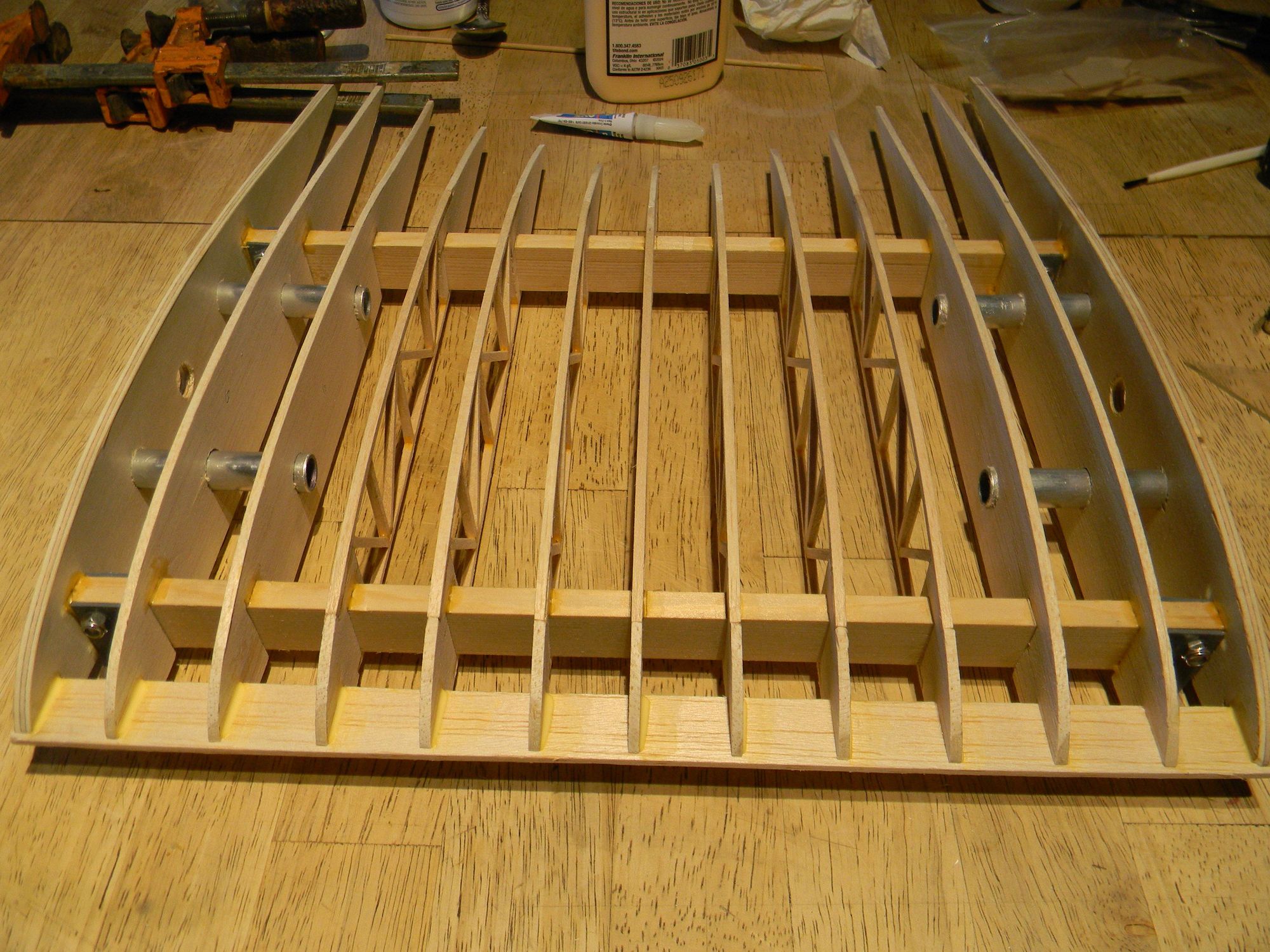
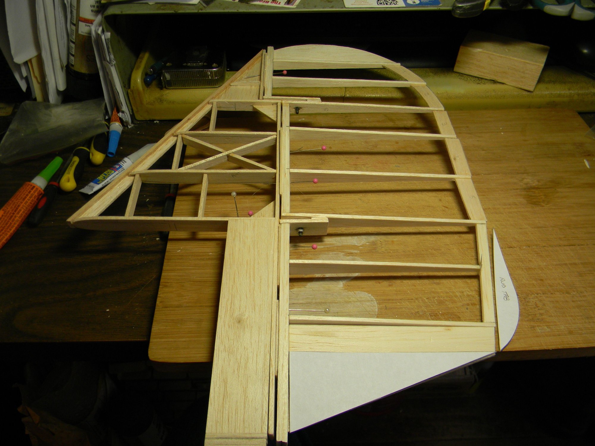
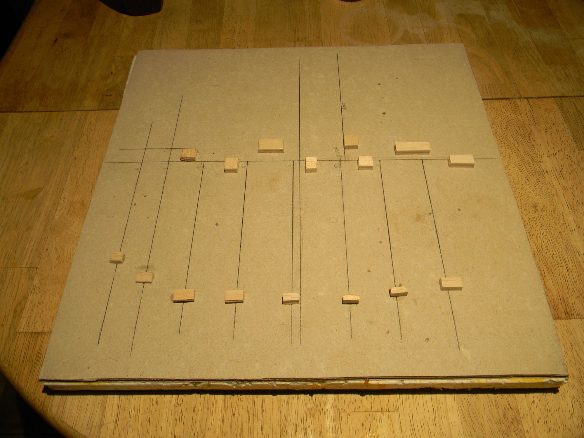
The cabane is built on spruce spars 13 Ľ” long x 3/8” thick x 1” tall. 5mm birch plywood root ribs have a 15 1/4” chord, with the next 2 solid ribs cut from hard balsa. I used 1/8” x 1/8” hard balsa sticks to build up the remaining ribs. 16 gauge sheet metal was used to fabricate strut mounts to bolt to the spars using 5mm bolts. ˝” aluminum tubing is used for wing mounting with corresponding aluminum rods built into the top wings for easy field assembly/disassembly. Pic below shows all of the parts ready for assembly. Pile of stuff in the lower right hand corner of the pic is the trailing edge strips.
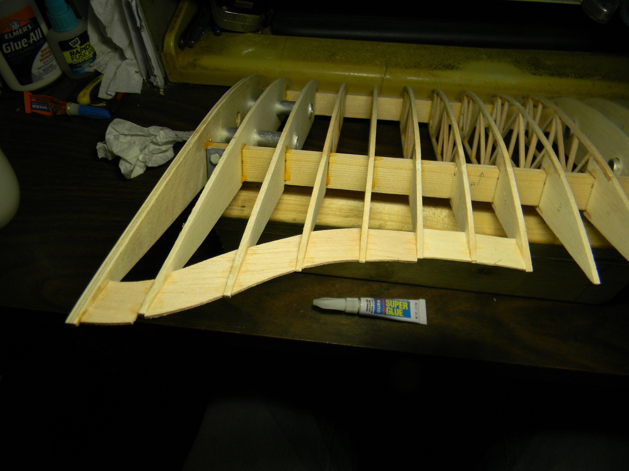
After doing spacing layout on the spars, assembly was straightforward beginning with the center ribs.
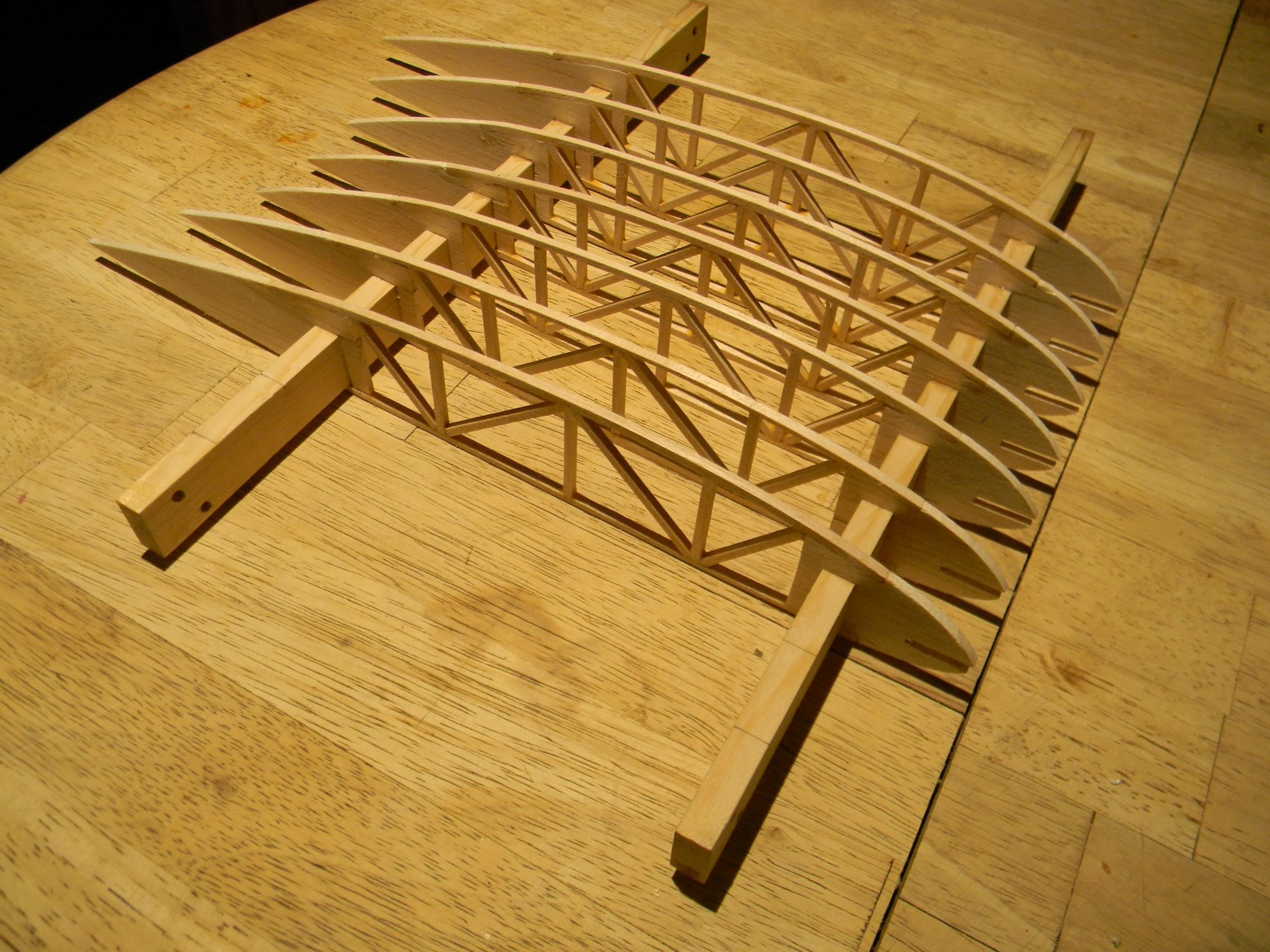
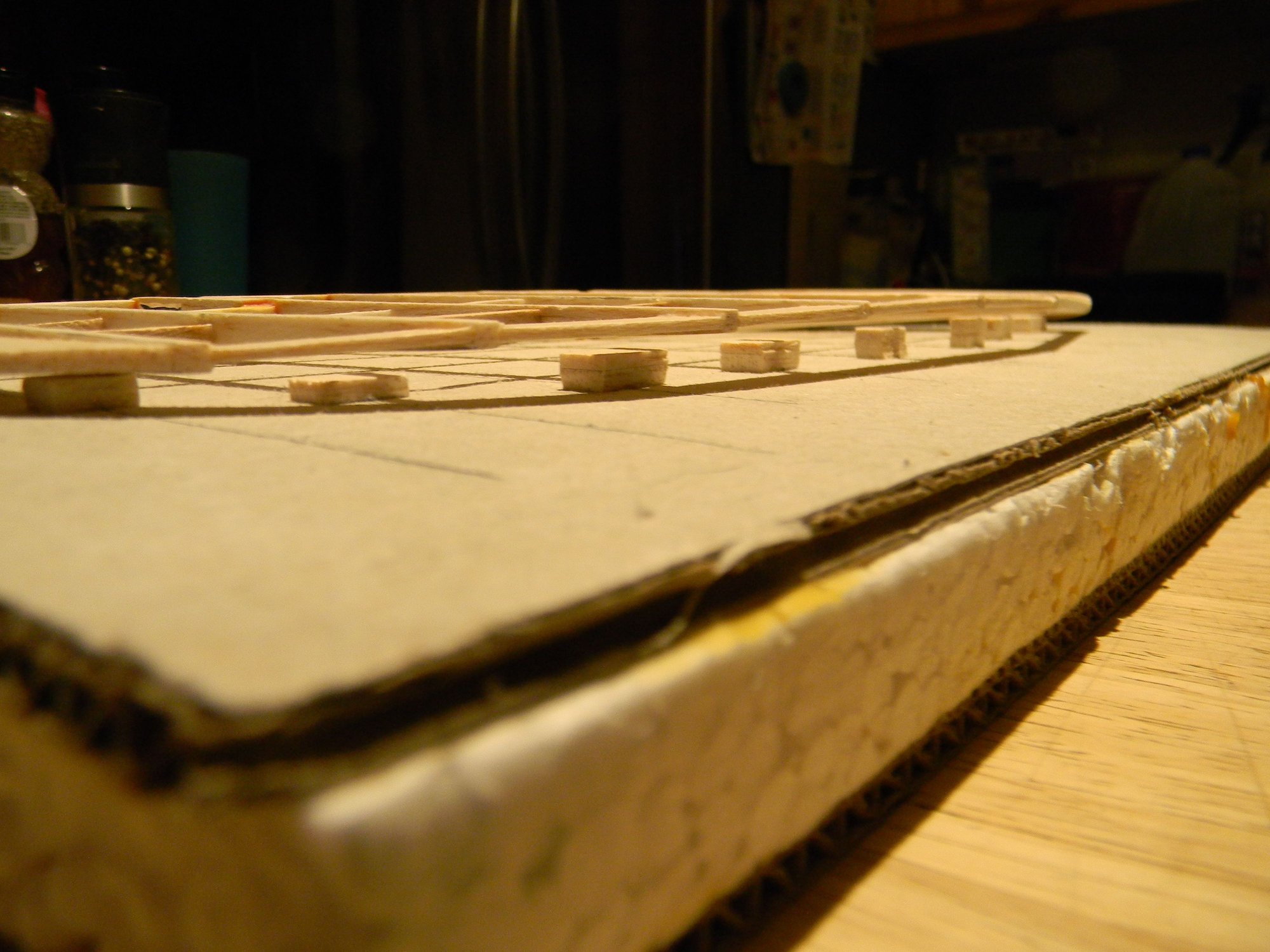
With center ribs in place a single drop of thin CA was added to each rib at the front and back spar to tack them into position. Strut mounting brackets were installed and root ribs put into position.
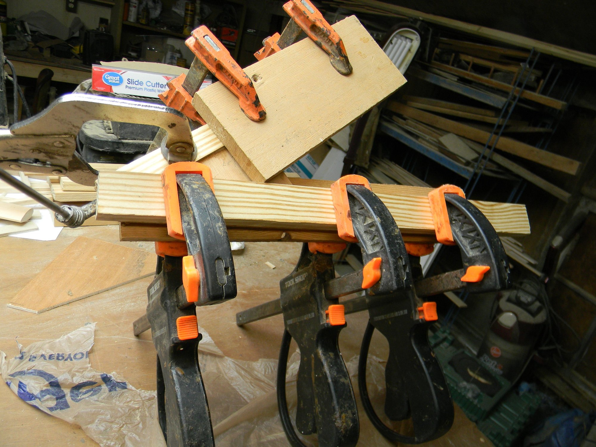
With root ribs in position, the cabane was checked for symmetry to make sure the spars are at a true right angle to the root ribs and parallel to each other. Everything checked ok except for a slight amount of twist leaning toward the port side root rib. So, a clamp was added to bring everything into alignment, the remaining ribs installed and everything glued into position using Titebond 2.
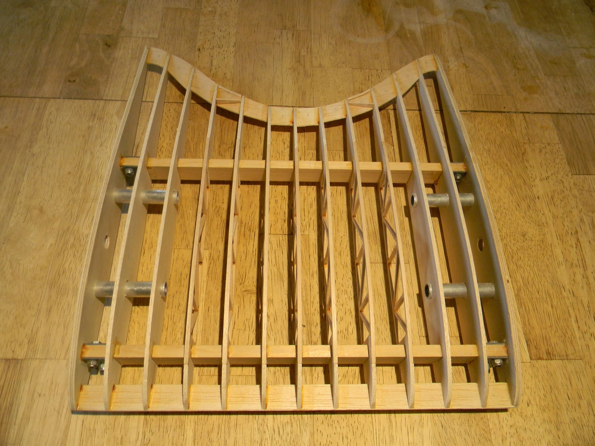
A 1/8” x ľ” hard balsa leading edge was installed after the Titebond had set then the take down tubes were epoxied to the ribs. Leading edge was locked in place using thin CA.
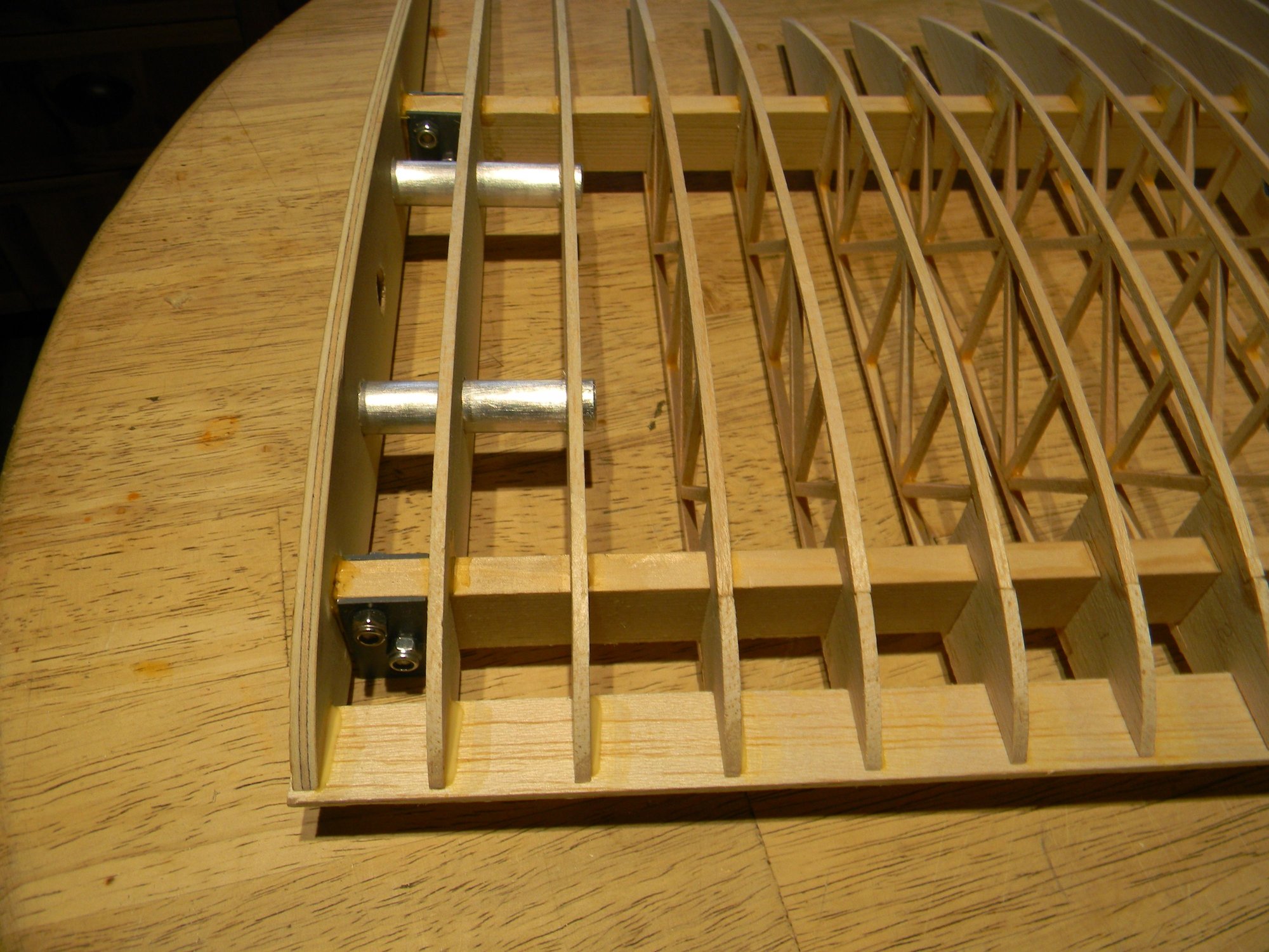
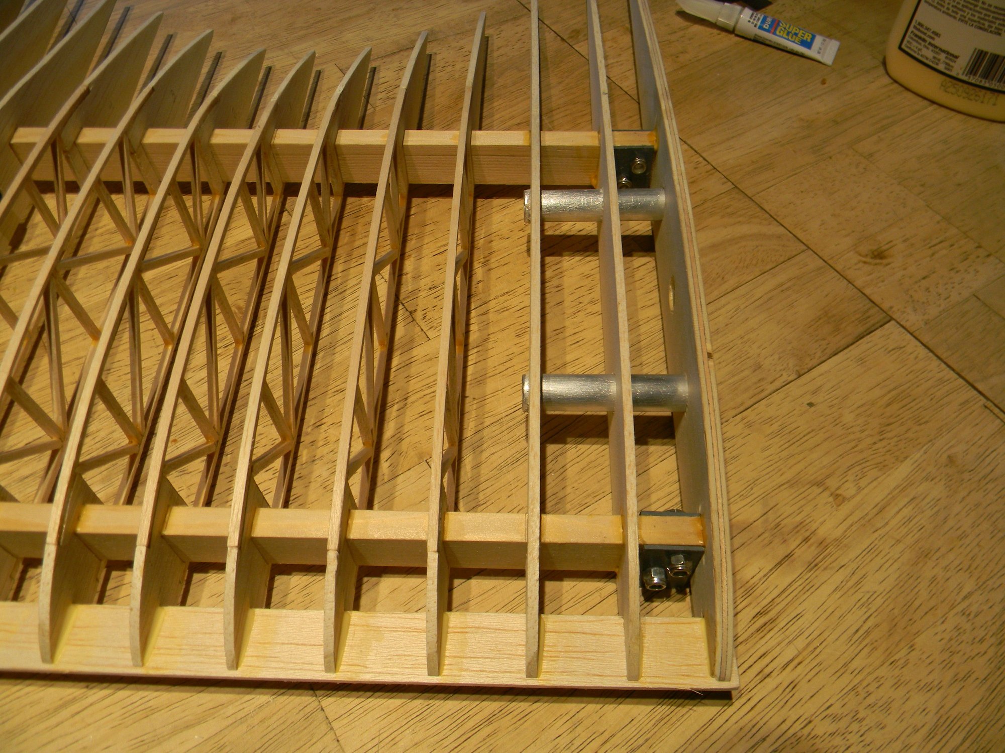
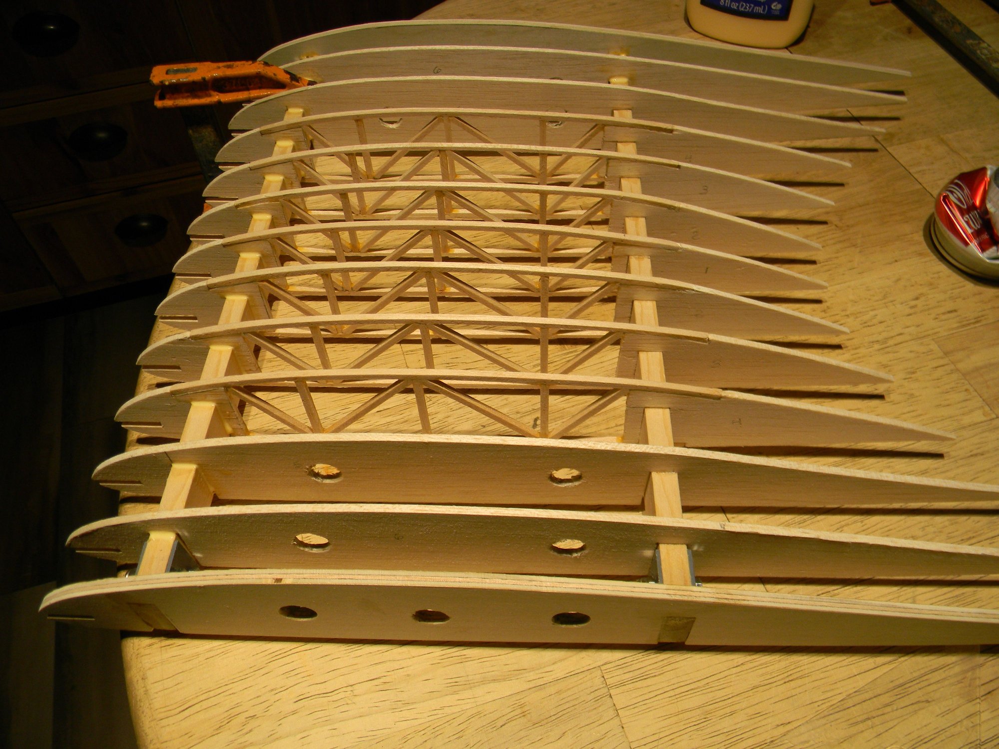
Completed assembly sans trailing edge strips.
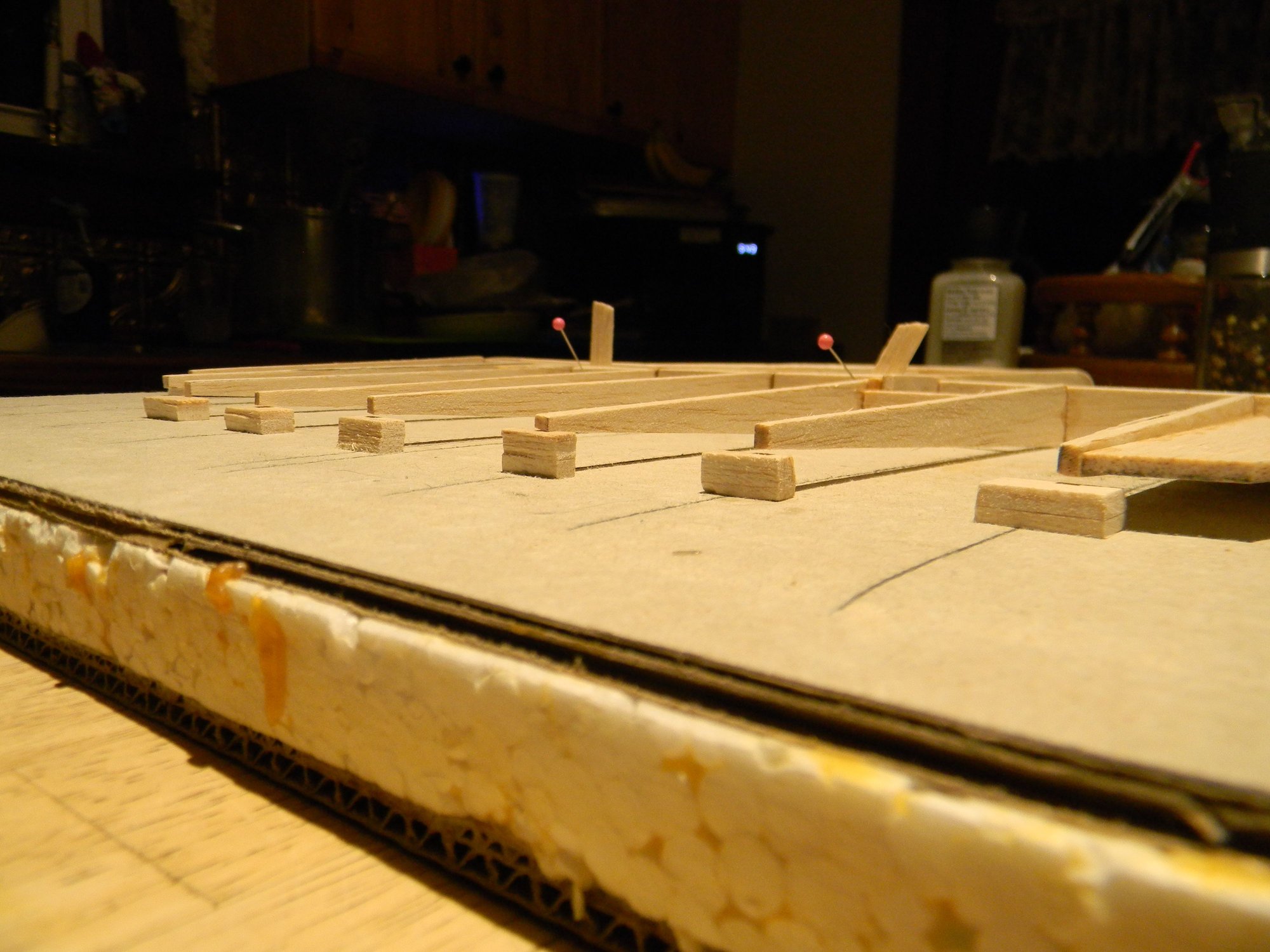
What follows next is the tedious task of installing the trailing edge strips. I chose this method to replicate how the wing ribs look on the full size ship; they’re clearly visible under the skin right out to the very tip of the leading and trailing edges. How else would one achieve this appearance?
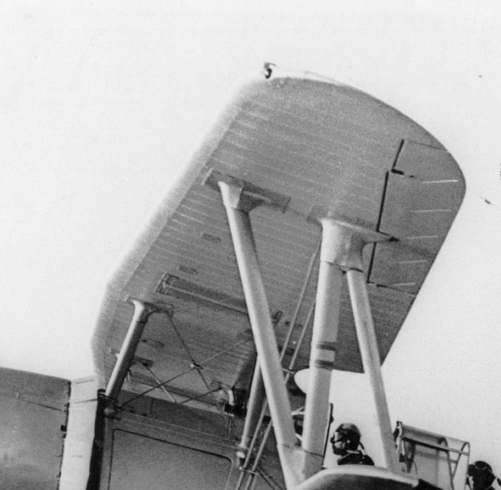
Ribs visible under the skin from edge to edge.
Gluing in the trailing edge.
And finally, pictured below, is the finished cabane ready to install complete with hand holds. Assembly as pictured weighs 10 ounces; a little heavier than what I’d like to see but I guess we’ll keep it. This brings the total weight to 55.5 ounces or roughly 3 ˝ pounds.
In the next posting we’ll dive into building the tail section. See you then.
Hank
Every pic studied shows consistent taper from the center rib out to make the radius but the airfoil shape at the trailing edge is not consistent to NACA CYH data at the deepest point of the radius. I found the clearest image of this is a Lukgraph model built by Jan_G posted on largescaleplanes.com:
After spending days trying to figure this out I finally decided to forget about the actual CYH airfoil trailing edge datum and freehand the trailing edge of the center ribs using CAD. Once that was settled it became a simple matter of generating the remaining rib profiles, printing the patterns and building the ribs.
The cabane is built on spruce spars 13 Ľ” long x 3/8” thick x 1” tall. 5mm birch plywood root ribs have a 15 1/4” chord, with the next 2 solid ribs cut from hard balsa. I used 1/8” x 1/8” hard balsa sticks to build up the remaining ribs. 16 gauge sheet metal was used to fabricate strut mounts to bolt to the spars using 5mm bolts. ˝” aluminum tubing is used for wing mounting with corresponding aluminum rods built into the top wings for easy field assembly/disassembly. Pic below shows all of the parts ready for assembly. Pile of stuff in the lower right hand corner of the pic is the trailing edge strips.
After doing spacing layout on the spars, assembly was straightforward beginning with the center ribs.
With center ribs in place a single drop of thin CA was added to each rib at the front and back spar to tack them into position. Strut mounting brackets were installed and root ribs put into position.
With root ribs in position, the cabane was checked for symmetry to make sure the spars are at a true right angle to the root ribs and parallel to each other. Everything checked ok except for a slight amount of twist leaning toward the port side root rib. So, a clamp was added to bring everything into alignment, the remaining ribs installed and everything glued into position using Titebond 2.
A 1/8” x ľ” hard balsa leading edge was installed after the Titebond had set then the take down tubes were epoxied to the ribs. Leading edge was locked in place using thin CA.
Completed assembly sans trailing edge strips.
What follows next is the tedious task of installing the trailing edge strips. I chose this method to replicate how the wing ribs look on the full size ship; they’re clearly visible under the skin right out to the very tip of the leading and trailing edges. How else would one achieve this appearance?
Ribs visible under the skin from edge to edge.
Gluing in the trailing edge.
And finally, pictured below, is the finished cabane ready to install complete with hand holds. Assembly as pictured weighs 10 ounces; a little heavier than what I’d like to see but I guess we’ll keep it. This brings the total weight to 55.5 ounces or roughly 3 ˝ pounds.
In the next posting we’ll dive into building the tail section. See you then.
Hank
The following users liked this post:
mgnostic (03-20-2026)
03-22-2026 | 03:27 AM
#13
Thread Starter
One of the more blatantly obvious inconsistencies found in the FSI plan is the shape of the rudder. The bloated profile is nowhere close to representing the true shape of the real thing. Compare the two pics below and you’ll see what I mean. But, as it is with most rubber powered models, oversize tail surfaces was/is common practice. We don’t want that.
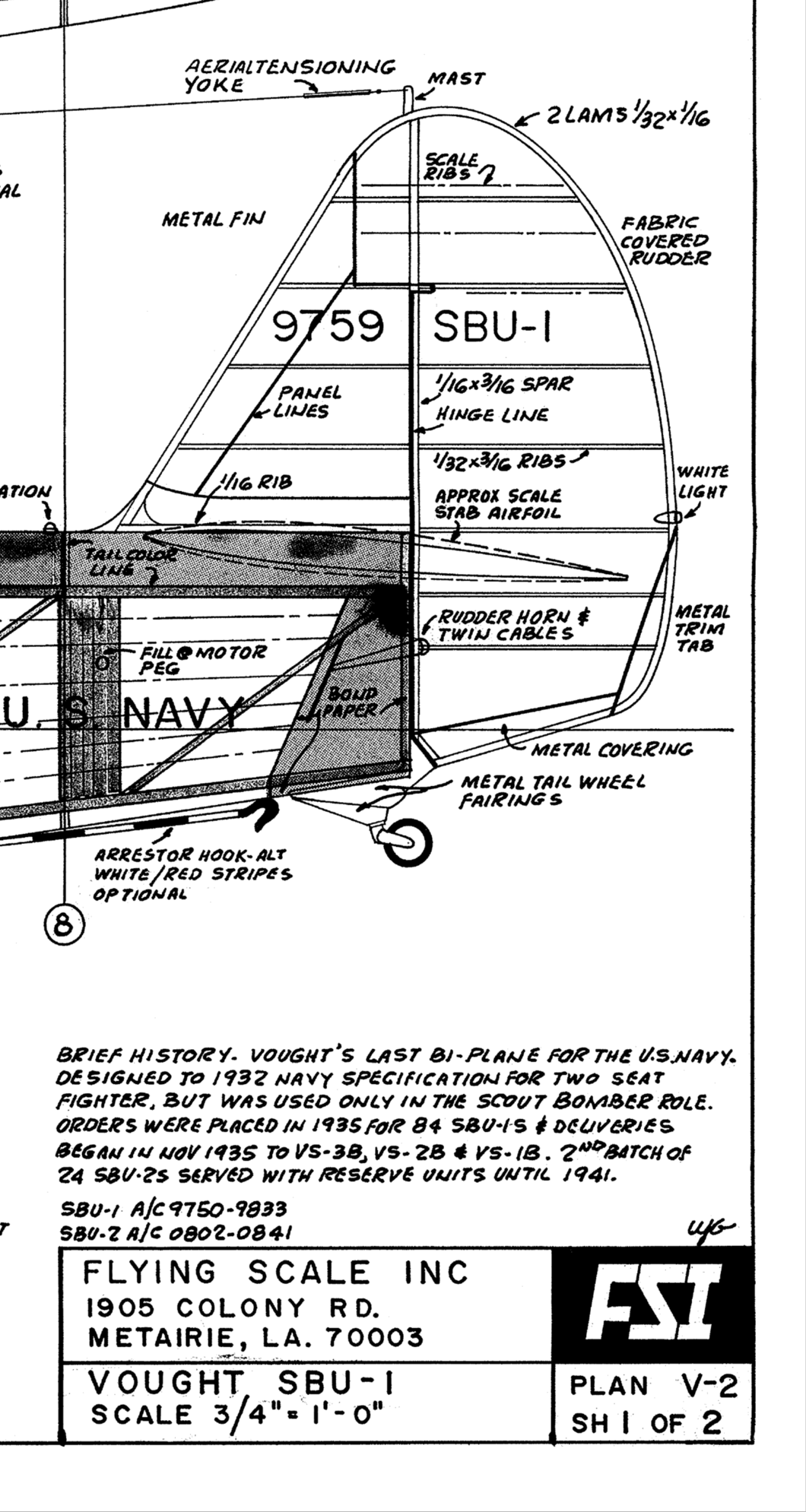
FSI rudder
Actual rudder
But, I will give credit where it’s due as the v stab/rudder rib spacing in the FSI plan is pretty much to scale. Another noticeable detail of the FSI plan is the h stab/elevator angle of incidence. This too is quite apparent in the Vought 3 view. This angle was measured as roughly 2 degrees using CAD. After reading various pros and cons of horizontal stabilizer incidence, I chose not to design this 2 degrees into the h stab. Instead, it was designed with zero degrees incidence but adjustable to create the incidence if it is really needed. I could find no reference to airfoil type used for the SBU tail surfaces so NACA 0012 was chosen as the most probable type. So, armed with 3 view data and about two dozen pics for reference it was off the drawing board to make the plans.
The first v stab/rudder prototype was built using soft balsa scraps. It was abandoned before completion due to several design flaws. After working out the bugs, a second prototype was built to completion.
Prototype rudder
After proving the design adequate, the final version was built using Ľ” basswood at all critical locations, hard balsa for ribs and short sections of 3/16” automotive brake line steel tubing as hinge point inserts. As it turned out, the brake line tubing inside diameter is a perfect fit for 4mm hinge bolts. You can see the bolts in position in the pic above and hinge point steel tubing insert in the pic below.
Steel tubing hinge point insert.
A quick and dirty jig was built to use for assembling the rudder.
Rudder jig
Placing the prototype rudder on the jig quickly shows what happens when one tries to build something like this by eye only.
Crooked 2nd prototype.
The jig worked as intended as the rudder built on it was straight and true in every aspect.
Rudder ready for the trailing edge.
A housing whittled from a 3/8” hardwood dowel was added to the rudder trailing edge for a bright white LED to replicate the white nav light seen on a full size SBU tail Just above the rudder trim tab,
SBU white nav light.
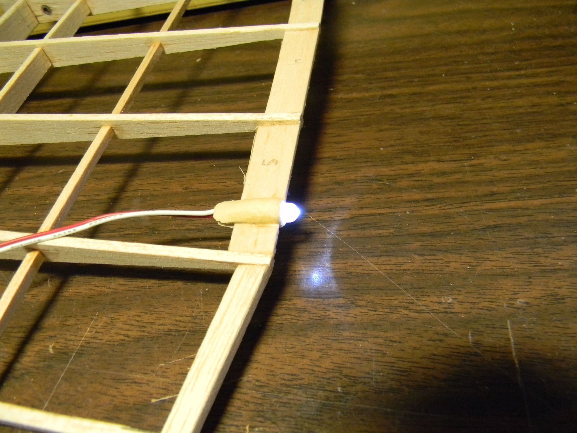
Bright white LED nav light.
Another quick and dirty jig was built for assembling the horizontal stabilizers. As with the v stab/rudder, all critical components are Ľ” basswood with 1/8” hard balsa ribs and steel inserts at hinge points.
H stab jig
Another quick and dirty jig for building elevators was tossed together using scrap wood and cardboard. This one was not so user friendly but it produced matching elevators that are straight and true to form.
Elevator jig
Ribs in place.
Trailing edge installed.
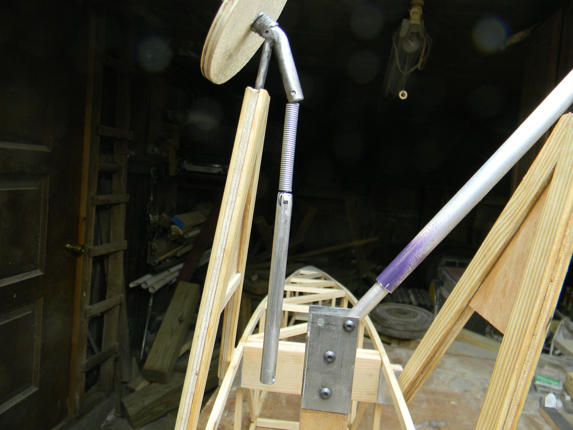
A hardwood block (riser) was made to which the v stab/rudder and h stab/elevator is mounted. This block serves as the adjusting point should there be a need for h stab incidence. Everything was assembled to the riser then the riser was bolted to the fuse frame. A pull-pull cable was installed, and, as mentioned earlier the tail wheel gear was adjusted more toward vertical to the correct rudder control arm geometry. The pull-pull cables connect to the tail wheel gear control arm via ball links. A channel in the riser houses the elevator push rod which connects to the elevator control horn also with a ball link. The elevator control horn is silver soldered to a length of 10-32 all thread, which is epoxied to the elevator halves inside spruce blocks. The spruce blocks are also epoxied to the elevator halves. And, of course, the elevator halves were tuned to match each other before everything was epoxied in place.
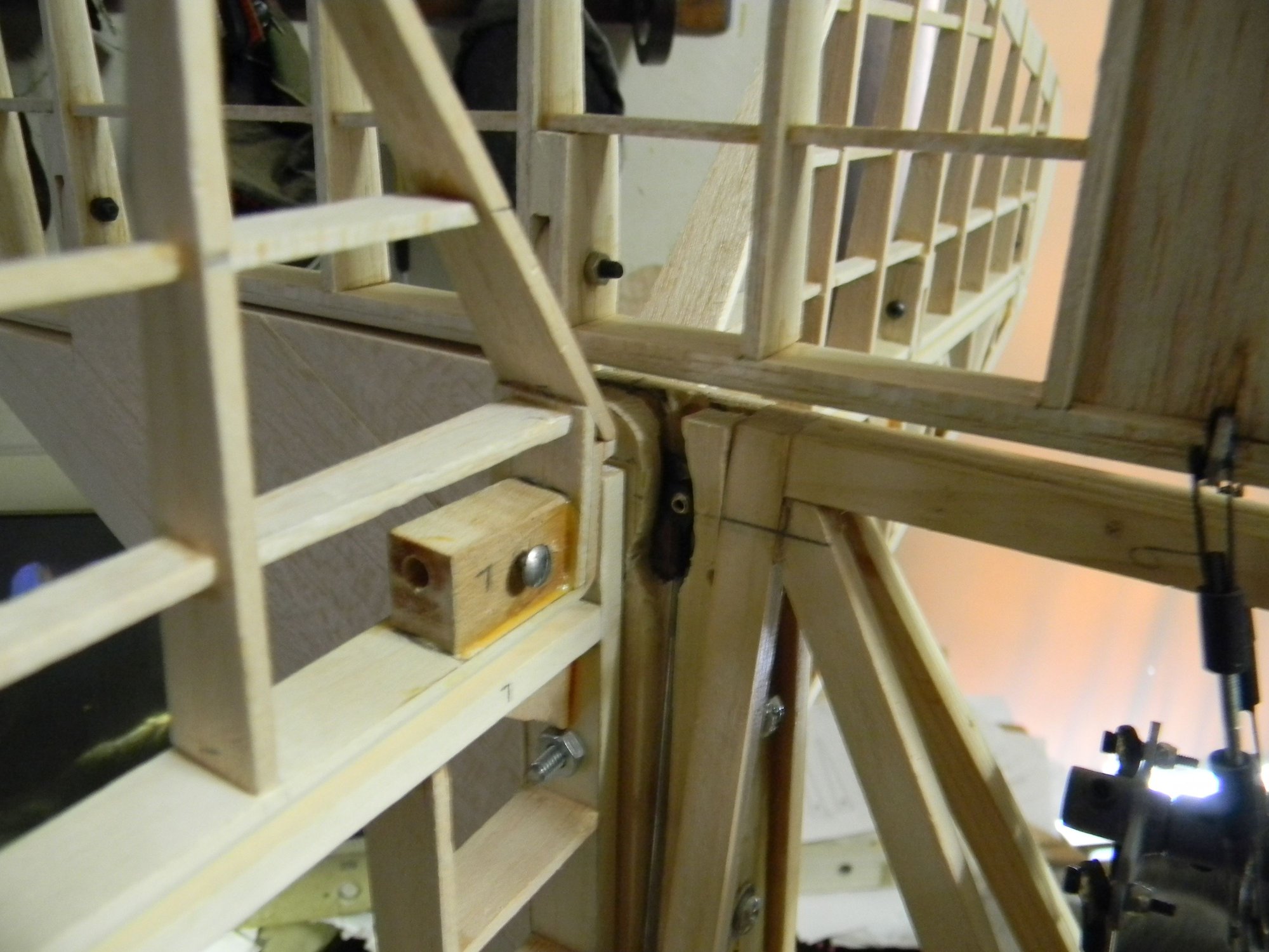
Elevator control linkage.
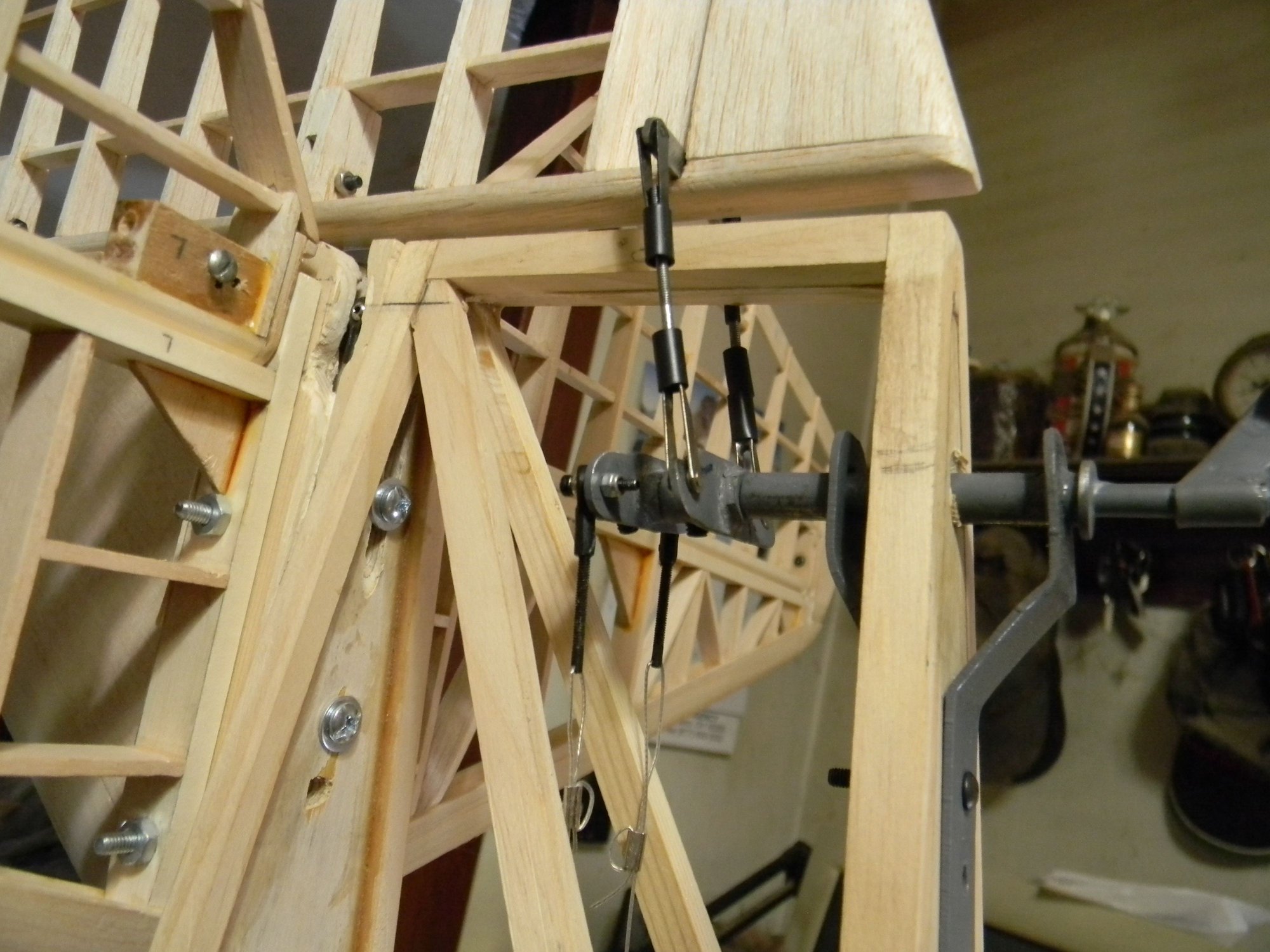
Rudder/tail wheel control linkage.
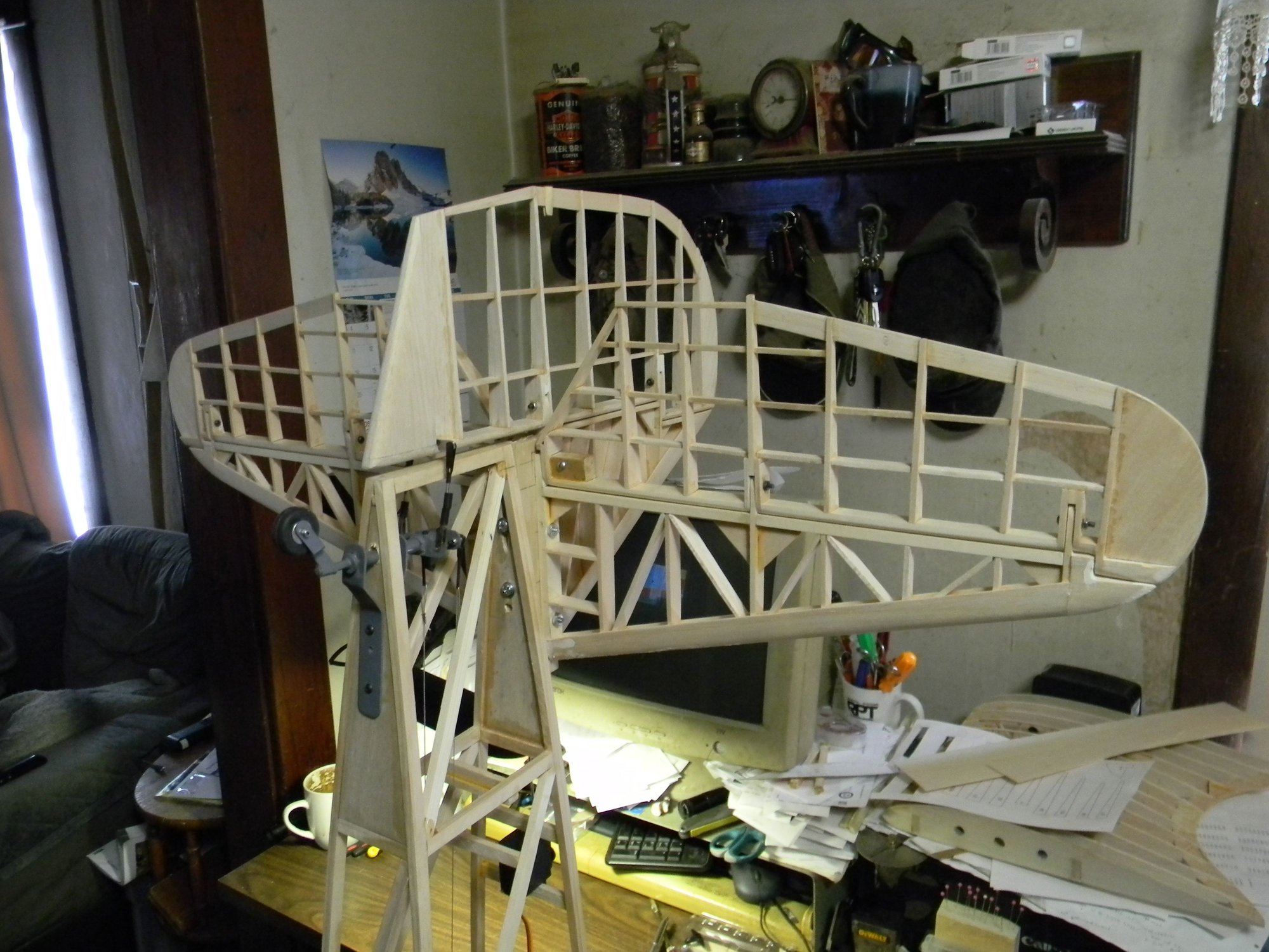
Empennage installed.
The fuse frame was set up and leveled to check side to side alignment of the h stab.
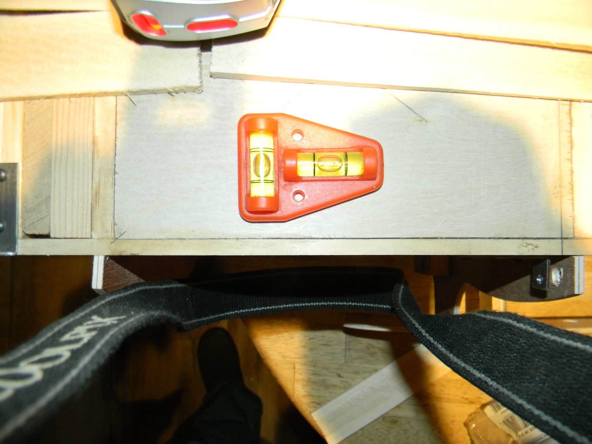
Fuse frame set up and leveled.
Alignment was checked using a laser level.
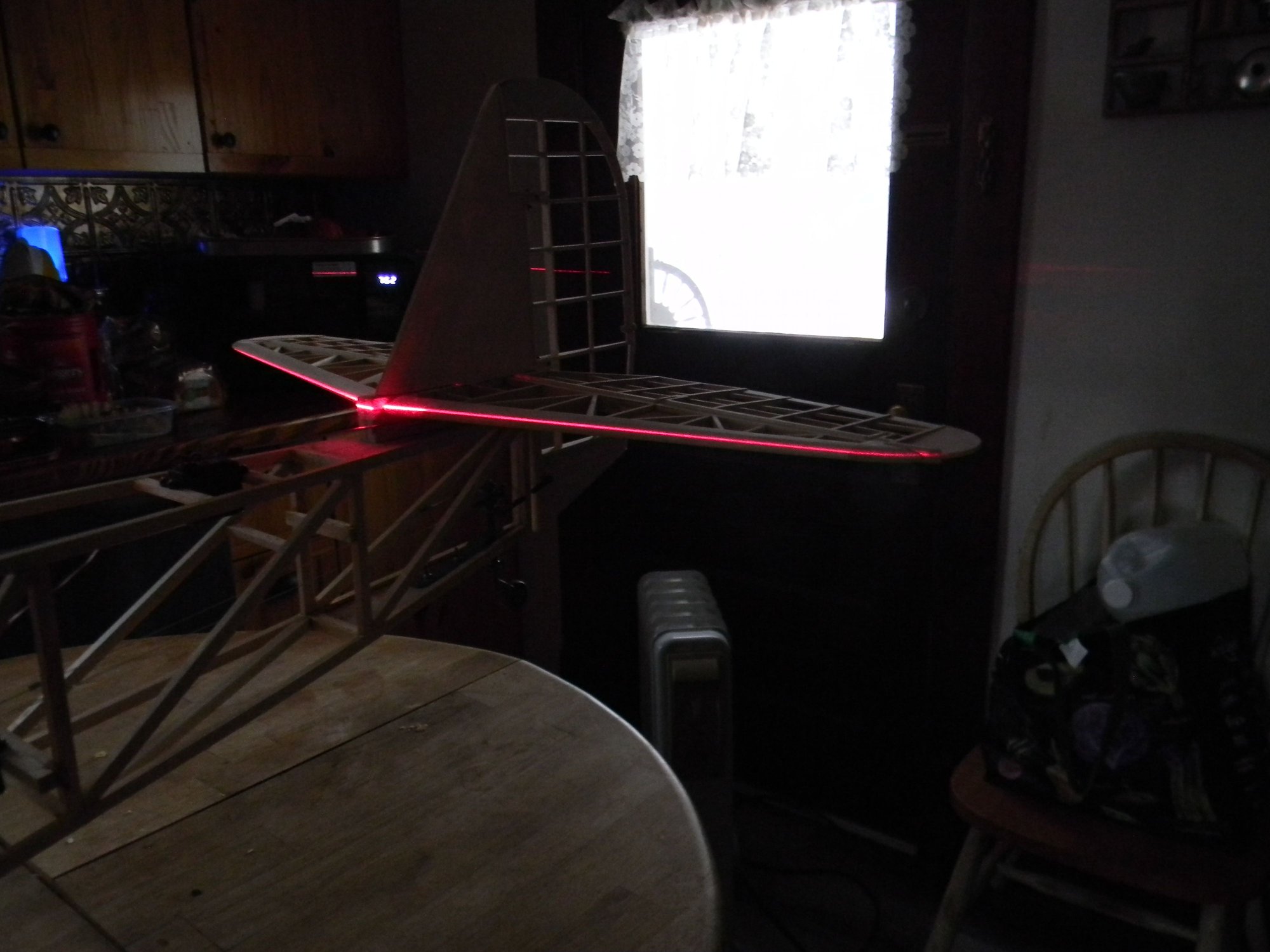
1/32" deviation side to side.
Starboard side stabilizer varies from port side about 1/32”. Not enough to worry about imo. I believe this tail assembly is a keeper. All that’s left to do here is covering and installing the trim tabs. Empennage weighs 11 ounces after sheeting the stabilizers. Next time we’ll look at building the lower wings. See you then.
Hank
FSI rudder
Actual rudder
But, I will give credit where it’s due as the v stab/rudder rib spacing in the FSI plan is pretty much to scale. Another noticeable detail of the FSI plan is the h stab/elevator angle of incidence. This too is quite apparent in the Vought 3 view. This angle was measured as roughly 2 degrees using CAD. After reading various pros and cons of horizontal stabilizer incidence, I chose not to design this 2 degrees into the h stab. Instead, it was designed with zero degrees incidence but adjustable to create the incidence if it is really needed. I could find no reference to airfoil type used for the SBU tail surfaces so NACA 0012 was chosen as the most probable type. So, armed with 3 view data and about two dozen pics for reference it was off the drawing board to make the plans.
The first v stab/rudder prototype was built using soft balsa scraps. It was abandoned before completion due to several design flaws. After working out the bugs, a second prototype was built to completion.
Prototype rudder
After proving the design adequate, the final version was built using Ľ” basswood at all critical locations, hard balsa for ribs and short sections of 3/16” automotive brake line steel tubing as hinge point inserts. As it turned out, the brake line tubing inside diameter is a perfect fit for 4mm hinge bolts. You can see the bolts in position in the pic above and hinge point steel tubing insert in the pic below.
Steel tubing hinge point insert.
A quick and dirty jig was built to use for assembling the rudder.
Rudder jig
Placing the prototype rudder on the jig quickly shows what happens when one tries to build something like this by eye only.
Crooked 2nd prototype.
The jig worked as intended as the rudder built on it was straight and true in every aspect.
Rudder ready for the trailing edge.
A housing whittled from a 3/8” hardwood dowel was added to the rudder trailing edge for a bright white LED to replicate the white nav light seen on a full size SBU tail Just above the rudder trim tab,
SBU white nav light.
Bright white LED nav light.
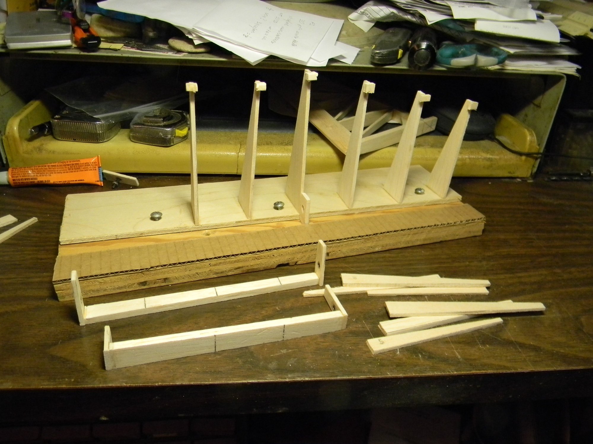
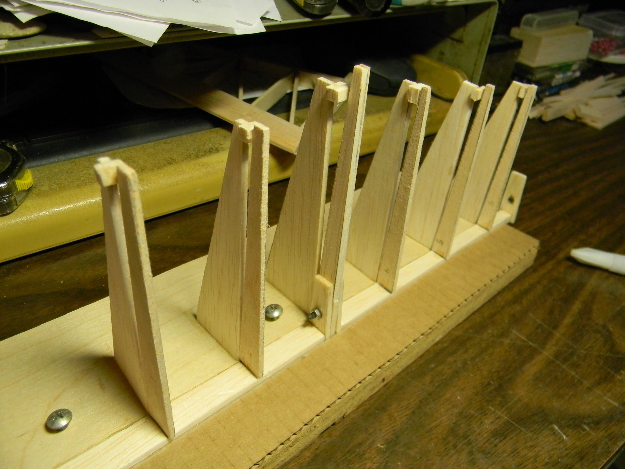
Another quick and dirty jig was built for assembling the horizontal stabilizers. As with the v stab/rudder, all critical components are Ľ” basswood with 1/8” hard balsa ribs and steel inserts at hinge points.
H stab jig
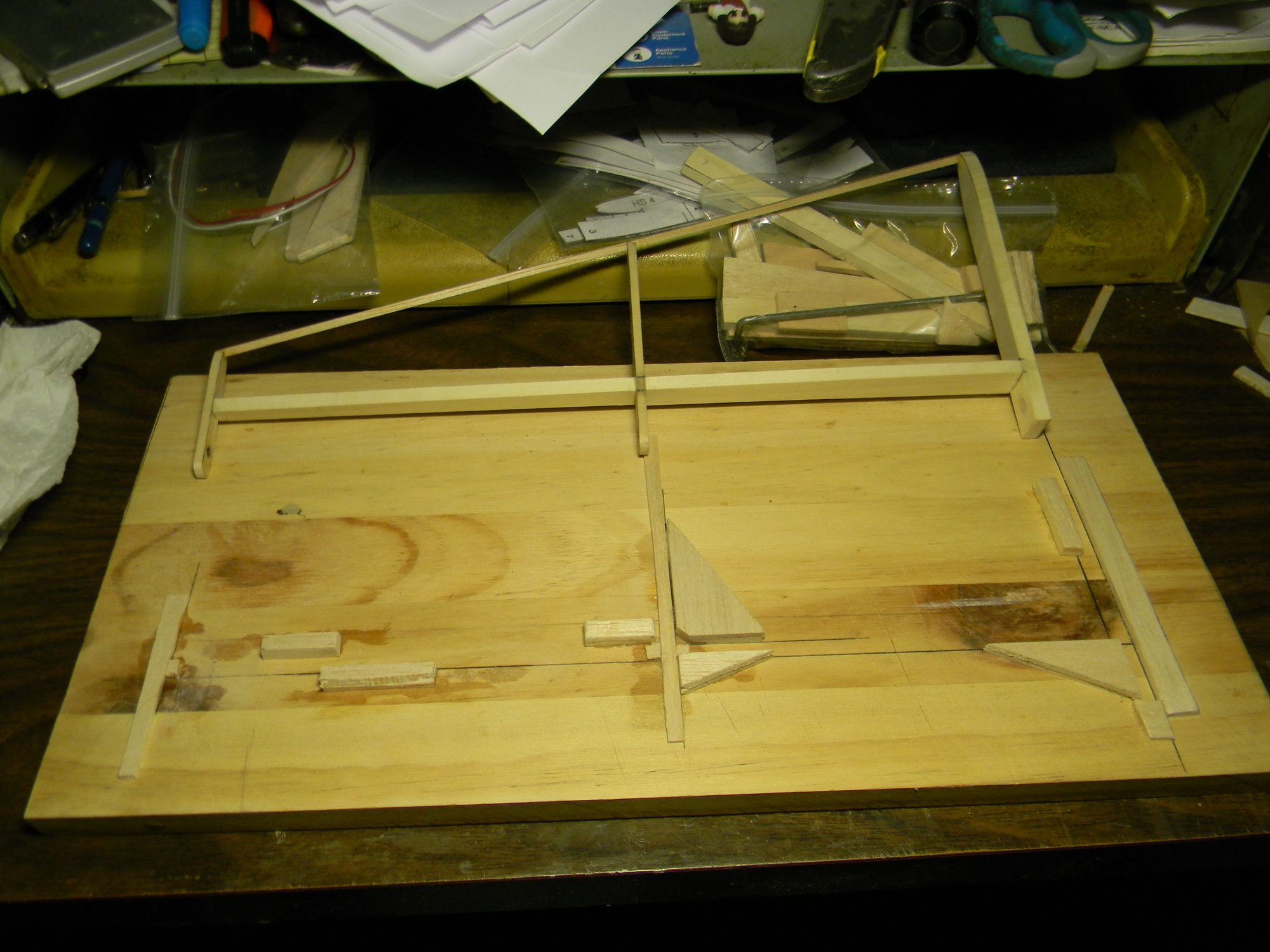
Another quick and dirty jig for building elevators was tossed together using scrap wood and cardboard. This one was not so user friendly but it produced matching elevators that are straight and true to form.
Elevator jig
Ribs in place.
Trailing edge installed.
A hardwood block (riser) was made to which the v stab/rudder and h stab/elevator is mounted. This block serves as the adjusting point should there be a need for h stab incidence. Everything was assembled to the riser then the riser was bolted to the fuse frame. A pull-pull cable was installed, and, as mentioned earlier the tail wheel gear was adjusted more toward vertical to the correct rudder control arm geometry. The pull-pull cables connect to the tail wheel gear control arm via ball links. A channel in the riser houses the elevator push rod which connects to the elevator control horn also with a ball link. The elevator control horn is silver soldered to a length of 10-32 all thread, which is epoxied to the elevator halves inside spruce blocks. The spruce blocks are also epoxied to the elevator halves. And, of course, the elevator halves were tuned to match each other before everything was epoxied in place.
Elevator control linkage.
Rudder/tail wheel control linkage.
Empennage installed.
The fuse frame was set up and leveled to check side to side alignment of the h stab.
Fuse frame set up and leveled.
Alignment was checked using a laser level.
1/32" deviation side to side.
Starboard side stabilizer varies from port side about 1/32”. Not enough to worry about imo. I believe this tail assembly is a keeper. All that’s left to do here is covering and installing the trim tabs. Empennage weighs 11 ounces after sheeting the stabilizers. Next time we’ll look at building the lower wings. See you then.
Hank
The following users liked this post:
mgnostic (03-22-2026)
03-22-2026 | 07:10 AM
#14
It's funny how once you ever start making jigs you wonder how you got by without them.
03-24-2026 | 04:24 AM
#15
Thread Starter
Hank
03-24-2026 | 07:51 AM
#16
Indeed. Not much of an issue with kit building but a necessity when scratch building imo. Right now, to save $$, i'm trying to figure out how to make a universal jig for both top and bottom wings. The idea is to build the bottom wing with 2 degrees or so washout, zero on top. Might be best to forget about trying to save $$ and build separate jigs?
Hank
Hank
The following users liked this post:
hank01 (03-24-2026)
03-24-2026 | 04:43 PM
#17
Thread Starter
Will all of the wing ribs have the built up structure? If the ribs were just cut from sheet I would suggest the old RCM wing jig. A wing jig needn't be expensive in money. You will have to do some geometry but you can calculate the amount needed to raise the trailing edge of the outermost rib to get the desired washout. From there you can cut a triangle shaped brace, the length of which is the span of the wing panel. The tip will be 2 degrees high and the root will be at 0 degrees. Your wing spars should help to hold everything in alignment.
Hank
The following users liked this post:
mgnostic (03-25-2026)


