There�s two tail wheel sizes used on the SBU. It appears, at least to me, that land based SBU�s had a larger tail wheel while carrier based planes had a ridiculously small tail wheel. We're modeling a carrier based plane so a small tail wheel is in order. Since there�s no commercial offering for 1/5 scale SBU-1 tail wheel gear, we�ll build it from scratch. There�s four tail wheel gear requirements: it must be sturdy; tail wheel must be steerable; wheel gear must operate the rudder; the entire assembly must be adjustable for setup alignment.
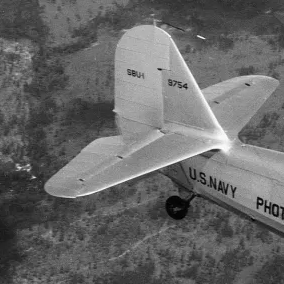 Big tail wheel.
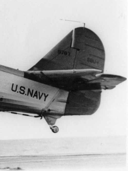 Small tail wheel.
A tail wheel assembly was fabricated using �� steel rod, 3/16� steel rod and 16 gauge sheet metal. A Du-Bro 1� tail wheel and 2mm axle bolt completes the component list. Pic below is the raw material to fabricate the components.
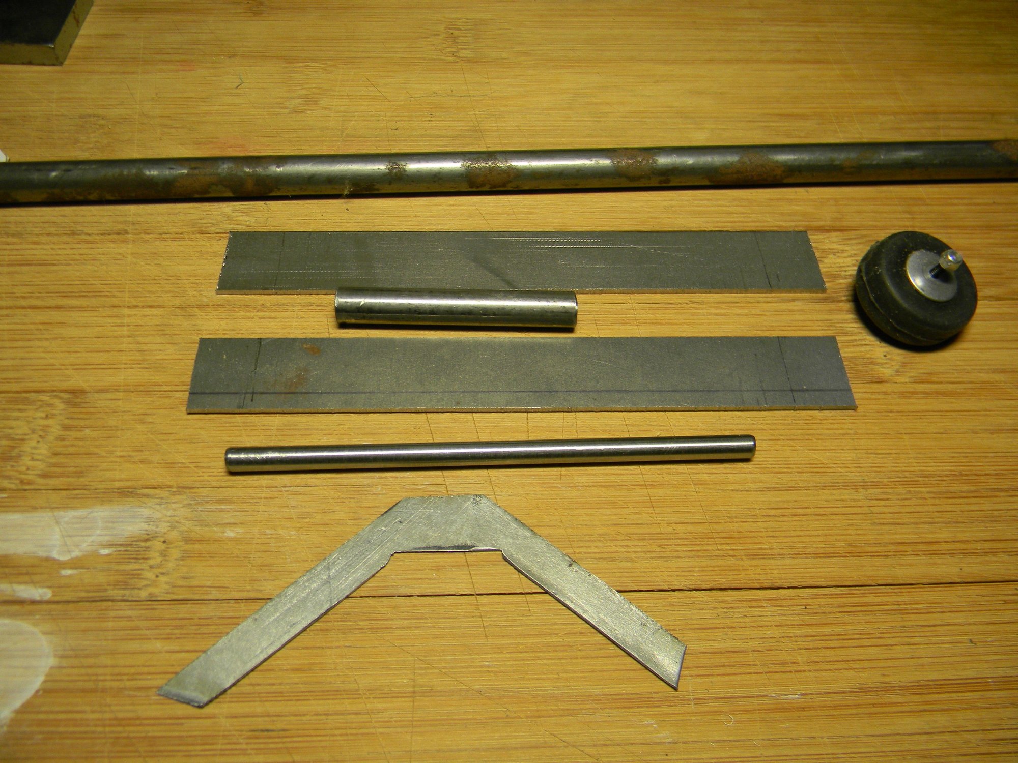 Raw goodies for a tail wheel assembly.
At the top of the pic is a rusty length of �� steel rod. One end of it was lathe turned to approximately 5/16� diameter then center drilled to accept a 3/16� rod. Cut from the turned portion is a 2� length to make the shaft bearing and two 3/8� lengths for control arm barrels. The shaft bearing is between the two longer pieces of sheet metal. After doing some layout work, gear mounting brackets (long pieces of sheet metal) was formed to shape and drilled for the shaft bearing. The tail wheel mounting yoke was then formed to shape and drilled for the 2mm axle bolt. A washer to act as a stop and the yoke was then silver soldered to the shaft. Below we have the completed components.
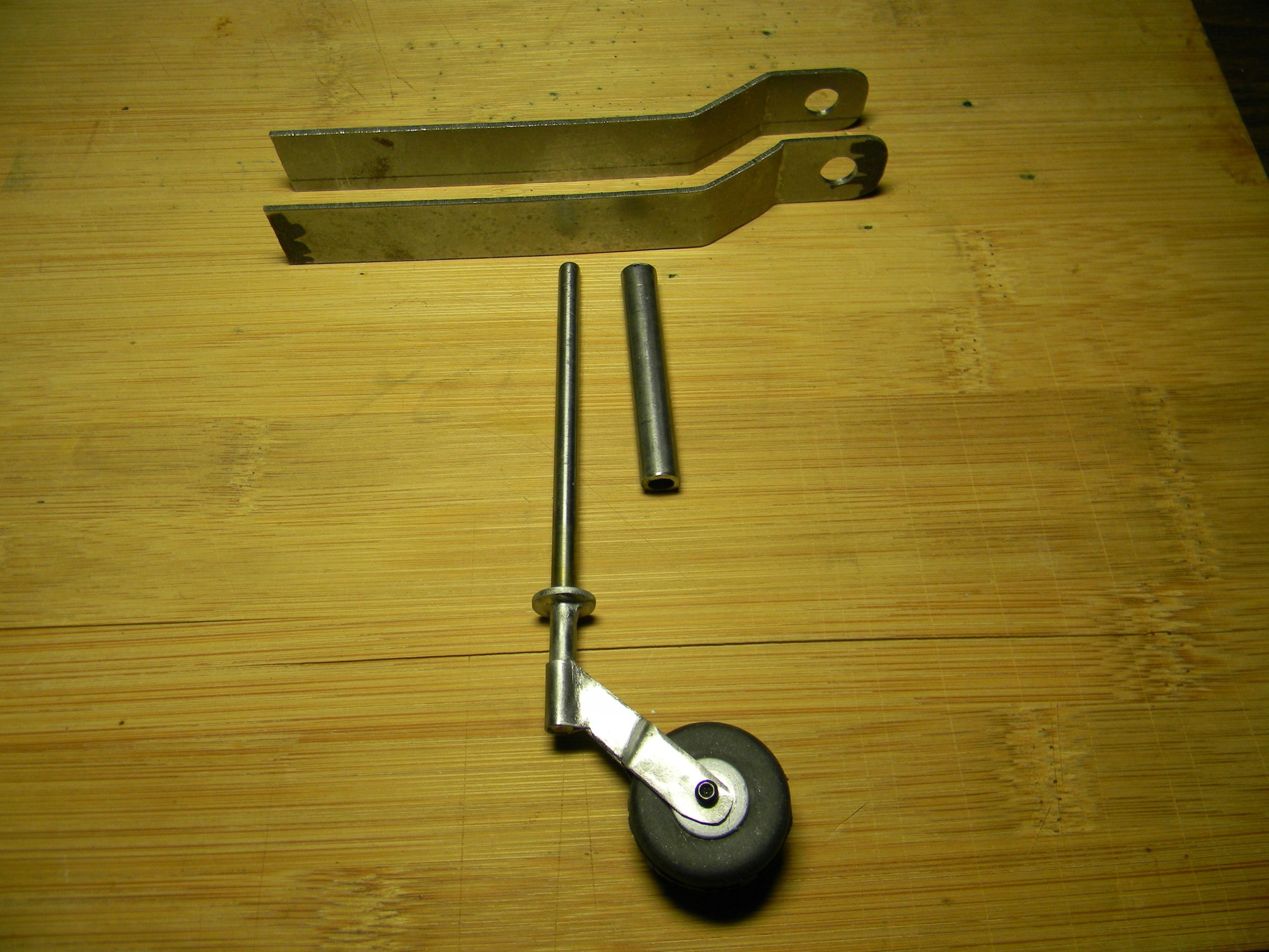 Fabricated components.
Pic below is a mock-up of how the gear fits to the fuse frame.
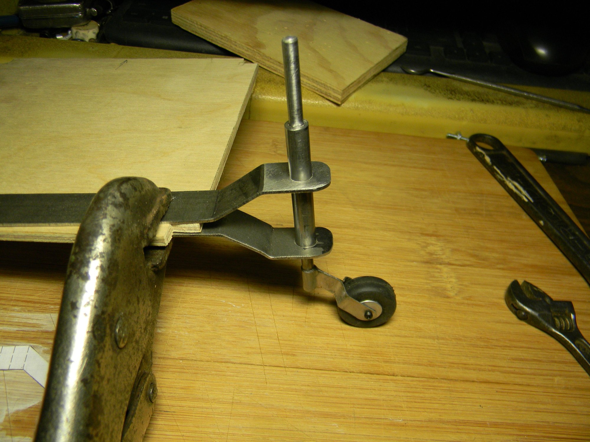 Mock up.
Two identical control arms fabricated from 16 gauge sheet metal along with the barrels mentioned above completes the tail wheel gear assembly. After shaping the wings of the arms and drilling for clevis pins, they were brazed to the barrels. The barrels were then drilled and tapped for 3/32� set screws, two on each barrel 180 degrees apart. The shaft bearing was silver soldered to the lower bracket after fitting to the fuse frame. Top bracket will be epoxied to the bearing after final fitting. Pic below shows the completed assembly.
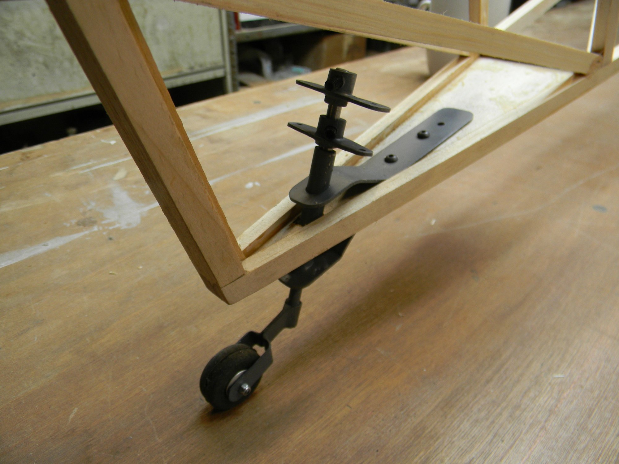 Completed tail wheel gear.
Top control arm connects to the servo via pull-pull cable. Bottom control arm connects to the rudder via push rods. Does this assembly meet all of the requirements? It is quite sturdy. The tail wheel is steerable. It will operate the rudder. And, it�s completely adjustable. In fact, angle of the tail wheel gear may require adjustment to more vertical while installing the pull-pull cable. We�ll see. And yes, we�ll use screw glue (locktite) on the set screws after everything is in alignment and adjusted accordingly. So there you have it- scratch built tail wheel gear from start to finish.
Next we�ll take a look at building the cabane. See you then.
Hank