Building the cabane proved a bit more challenging than anticipated. The stumbling block was the amount of taper and airfoil trailing edge shape toward the center where hand holds are located as shown in the top wing in the 3 view drawing. The deep radius at the center of the cabane complicated the matter.
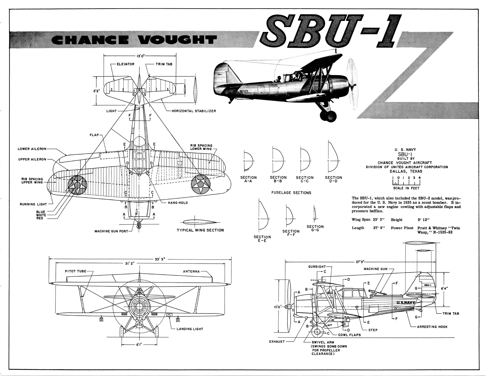
Every pic studied shows consistent taper from the center rib out to make the radius but the airfoil shape at the trailing edge is not consistent to NACA CYH data at the deepest point of the radius. I found the clearest image of this is a Lukgraph model built by Jan_G posted on largescaleplanes.com:
After spending days trying to figure this out I finally decided to forget about the actual CYH airfoil trailing edge datum and freehand the trailing edge of the center ribs using CAD. Once that was settled it became a simple matter of generating the remaining rib profiles, printing the patterns and building the ribs.
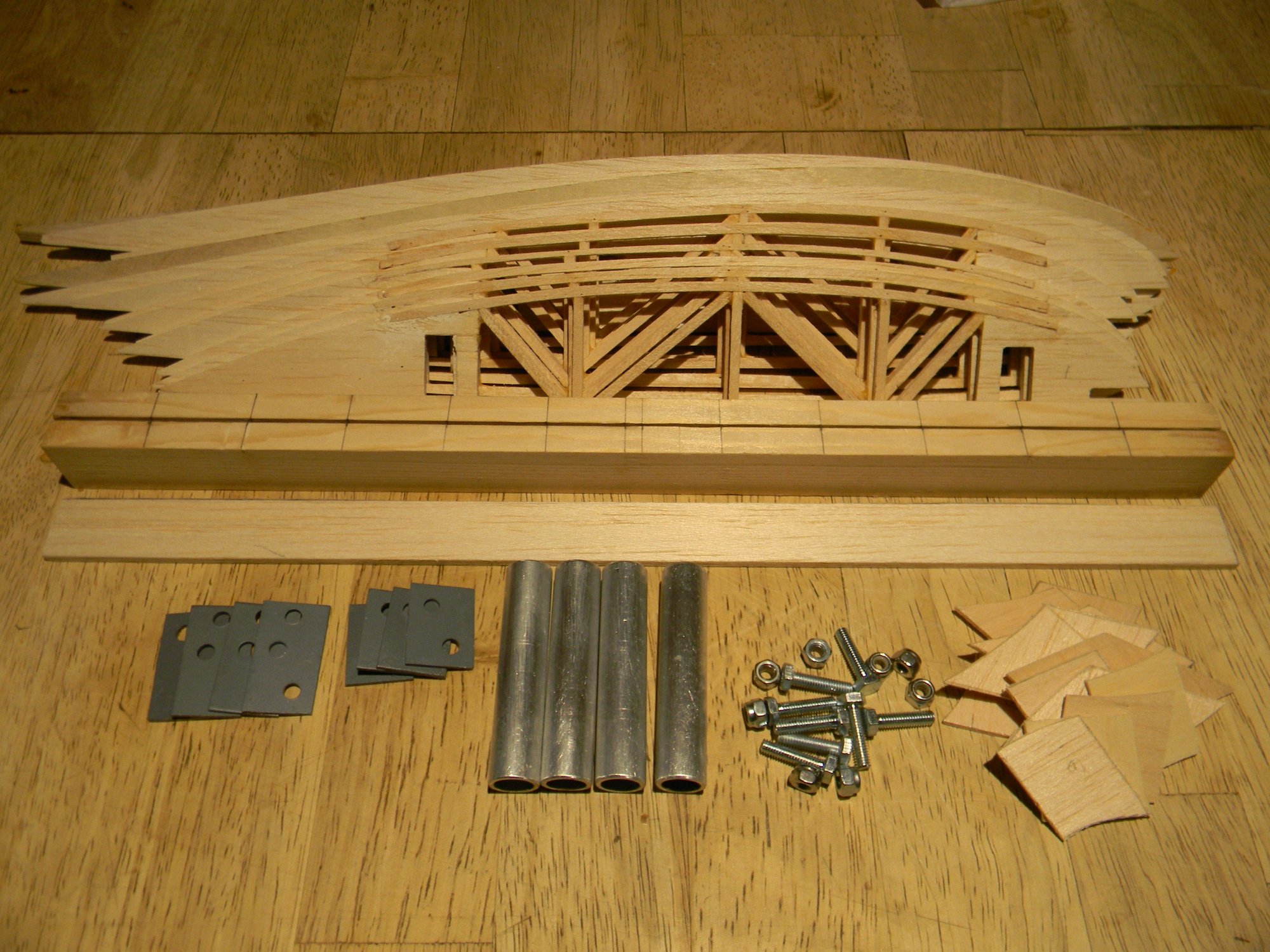
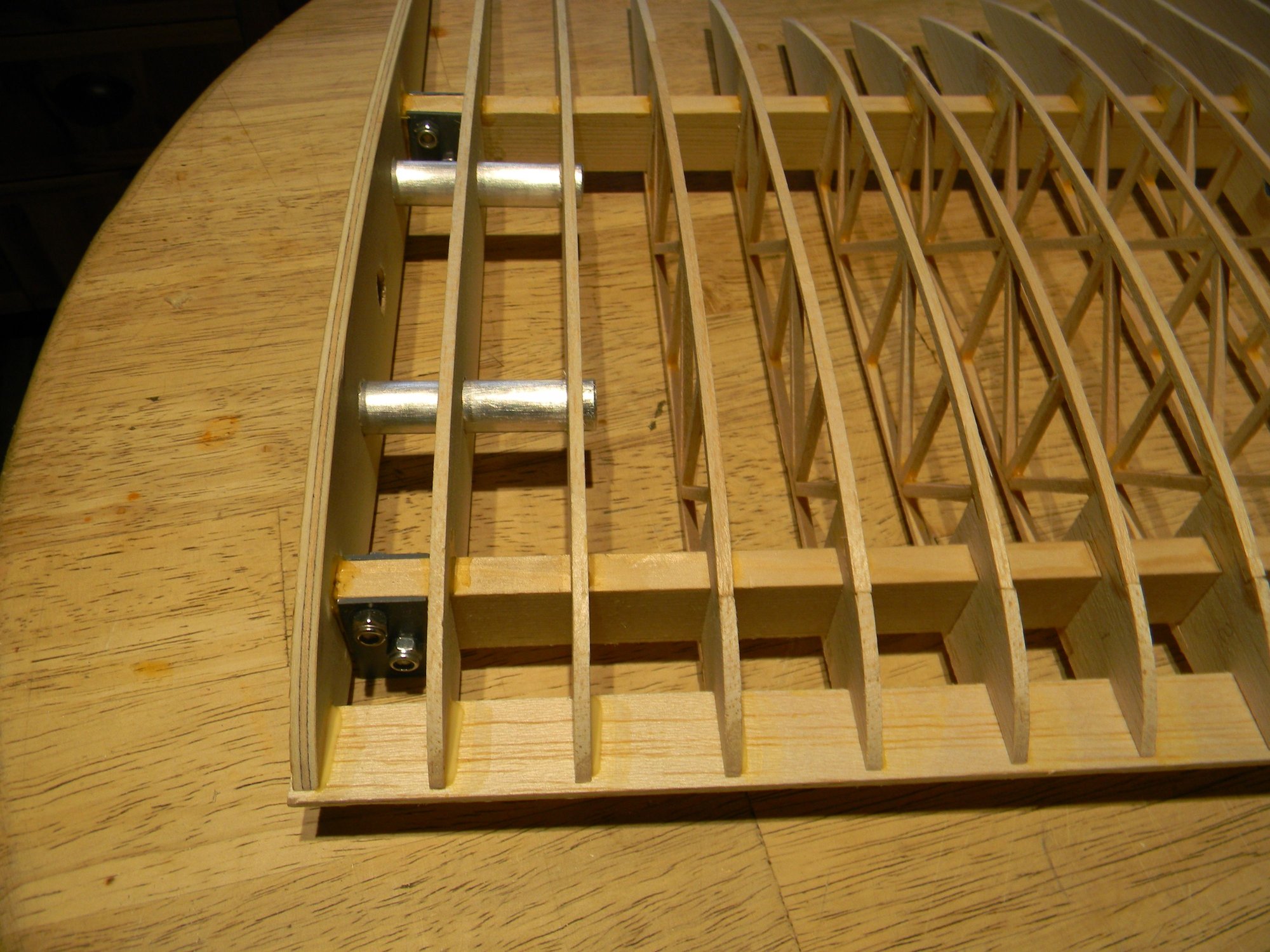
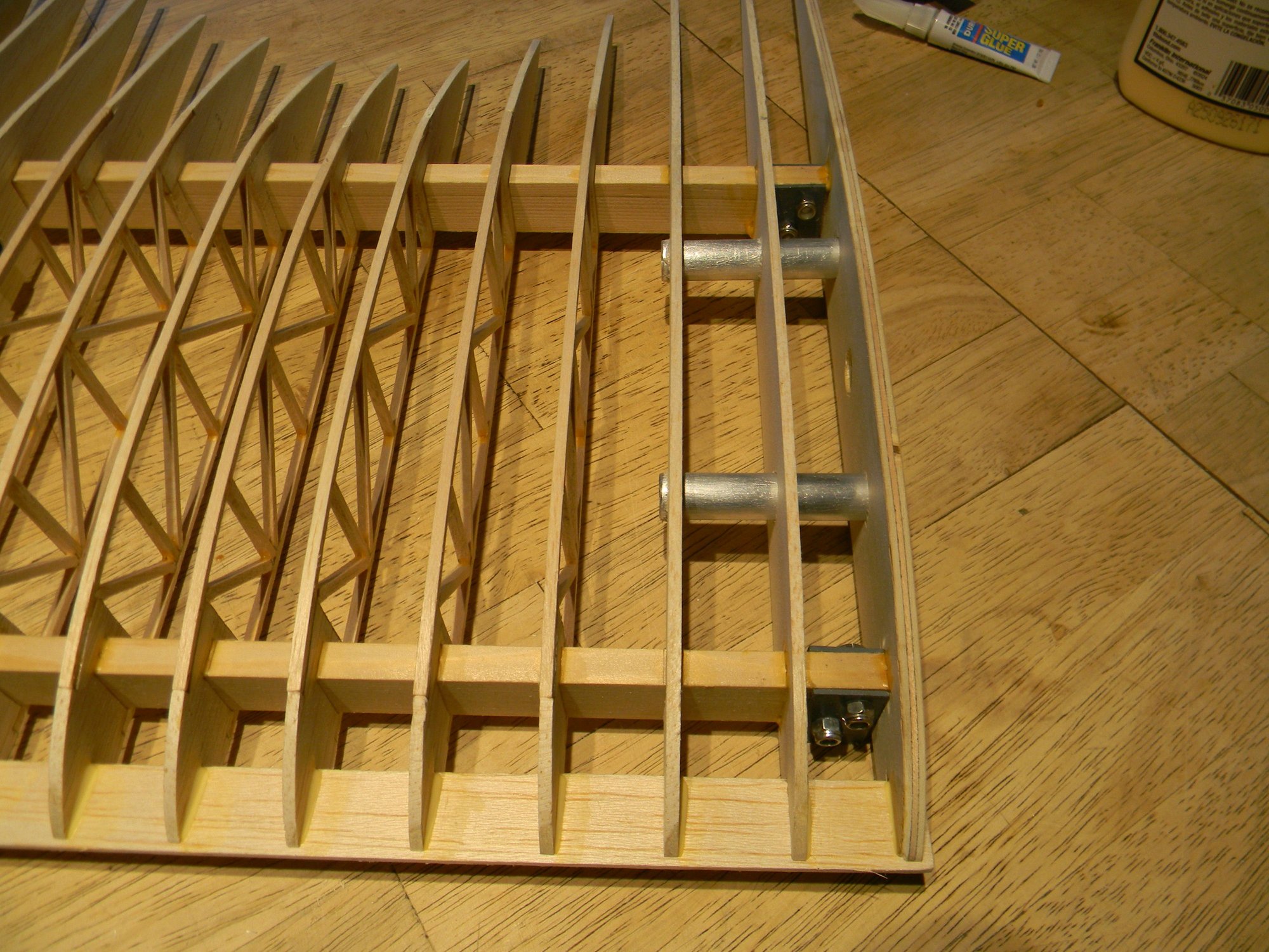
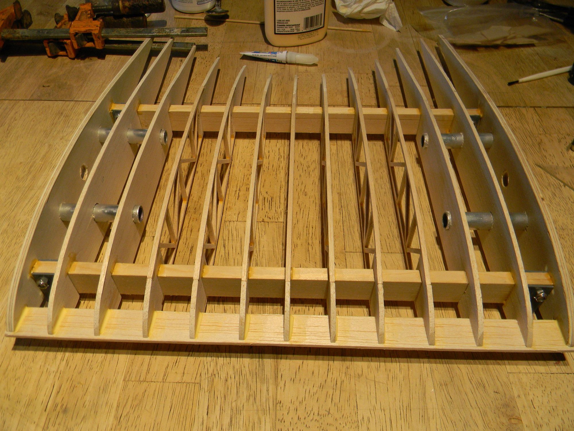
The cabane is built on spruce spars 13 �� long x 3/8� thick x 1� tall. 5mm birch plywood root ribs have a 15 1/4� chord, with the next 2 solid ribs cut from hard balsa. I used 1/8� x 1/8� hard balsa sticks to build up the remaining ribs. 16 gauge sheet metal was used to fabricate strut mounts to bolt to the spars using 5mm bolts. �� aluminum tubing is used for wing mounting with corresponding aluminum rods built into the top wings for easy field assembly/disassembly. Pic below shows all of the parts ready for assembly. Pile of stuff in the lower right hand corner of the pic is the trailing edge strips.
After doing spacing layout on the spars, assembly was straightforward beginning with the center ribs.
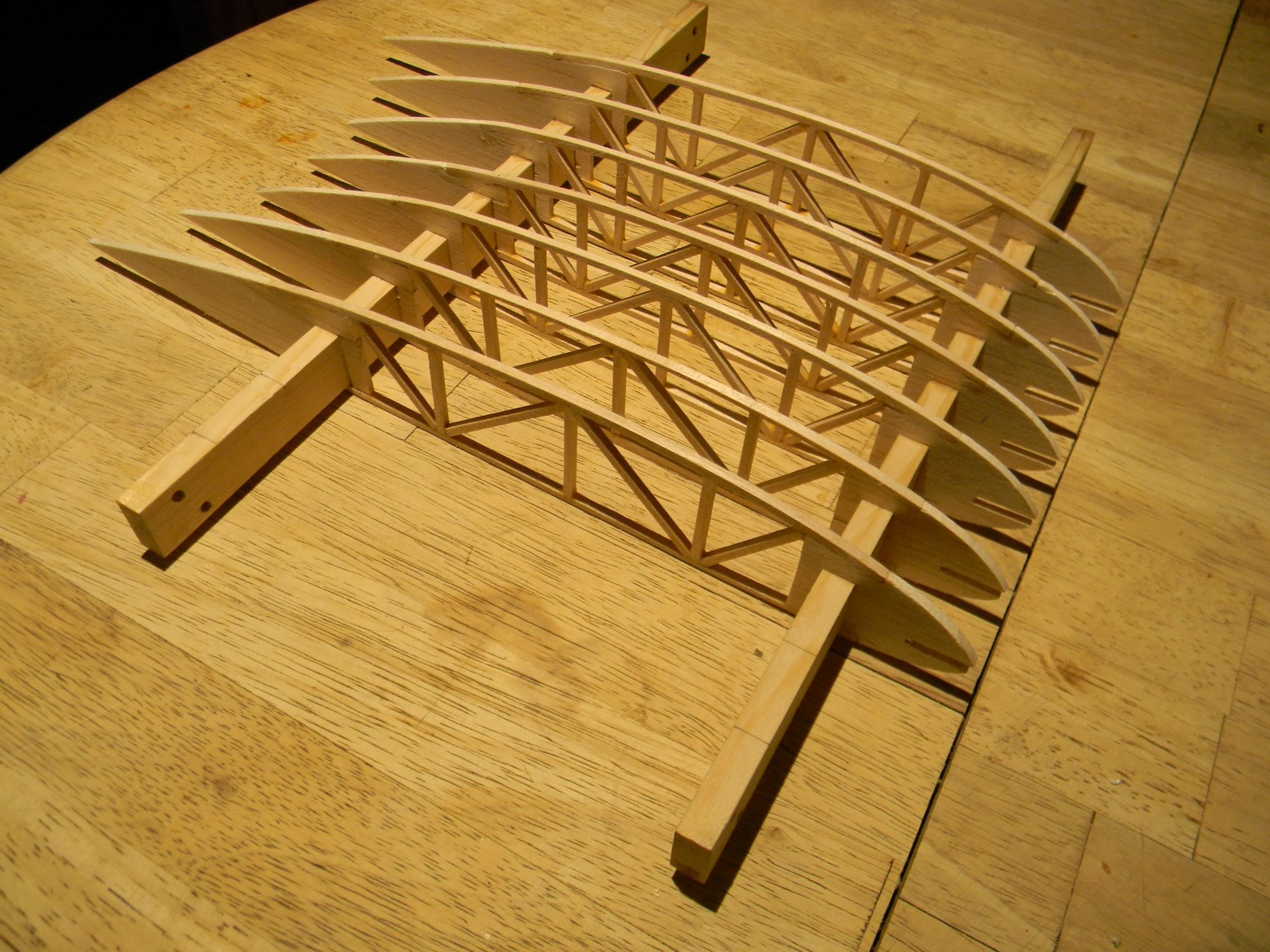
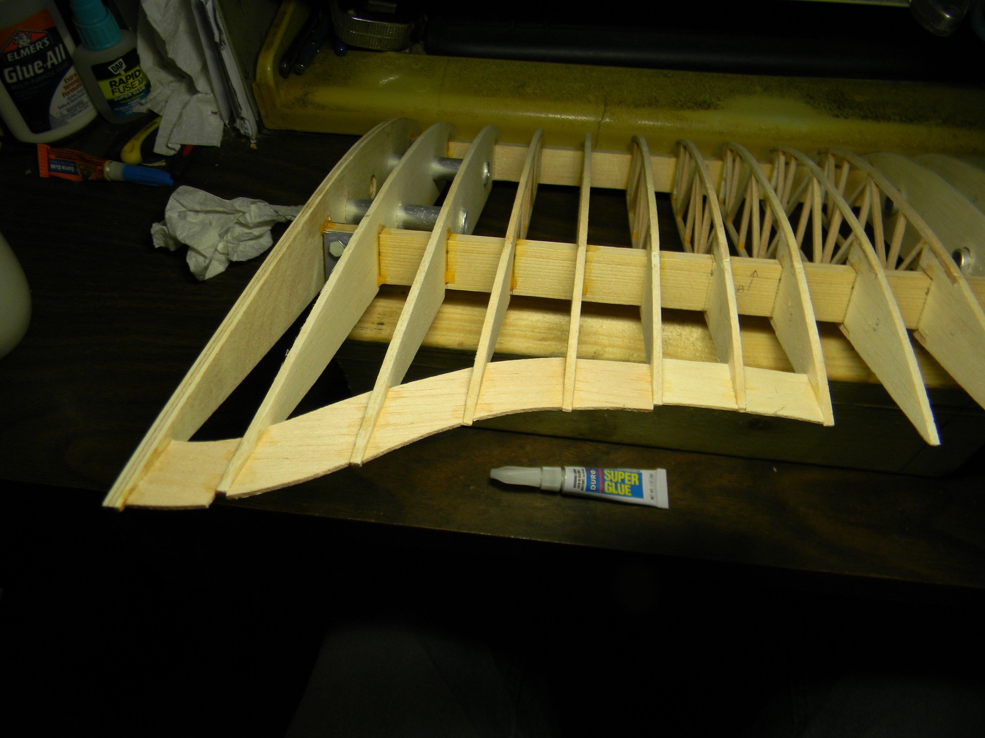
With center ribs in place a single drop of thin CA was added to each rib at the front and back spar to tack them into position. Strut mounting brackets were installed and root ribs put into position.
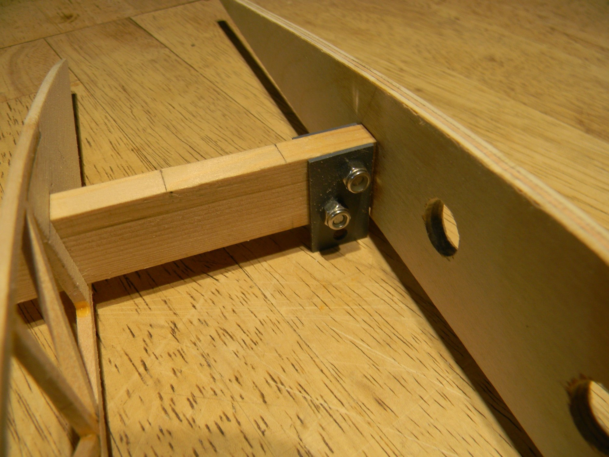
With root ribs in position, the cabane was checked for symmetry to make sure the spars are at a true right angle to the root ribs and parallel to each other. Everything checked ok except for a slight amount of twist leaning toward the port side root rib. So, a clamp was added to bring everything into alignment, the remaining ribs installed and everything glued into position using Titebond 2.
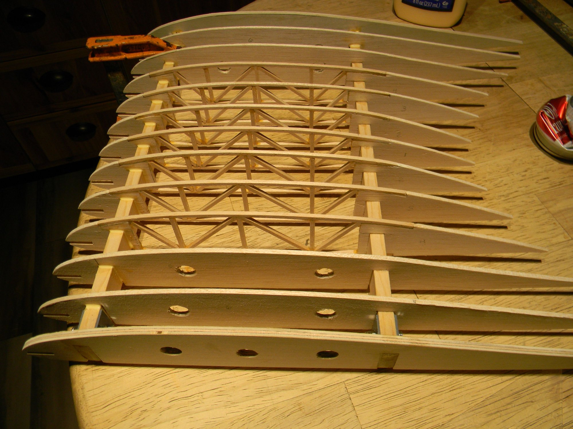
A 1/8� x �� hard balsa leading edge was installed after the Titebond had set then the take down tubes were epoxied to the ribs. Leading edge was locked in place using thin CA.
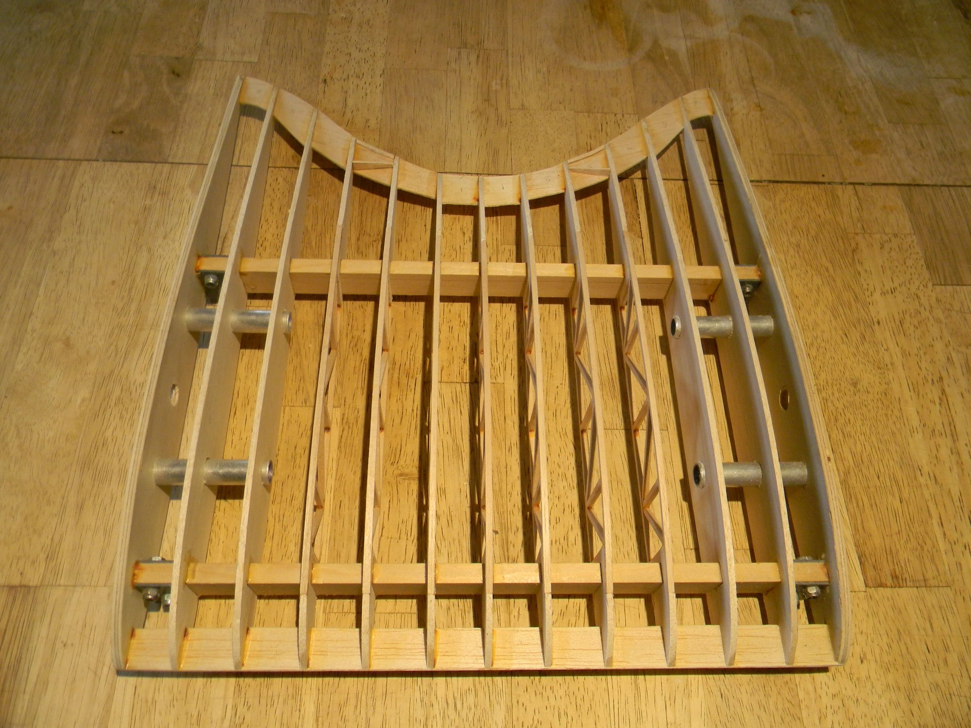
Completed assembly sans trailing edge strips.
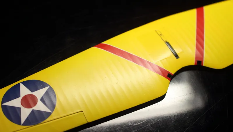
What follows next is the tedious task of installing the trailing edge strips. I chose this method to replicate how the wing ribs look on the full size ship; they�re clearly visible under the skin right out to the very tip of the leading and trailing edges. How else would one achieve this appearance?
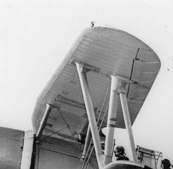 Ribs visible under the skin from edge to edge.
Gluing in the trailing edge.
And finally, pictured below, is the finished cabane ready to install complete with hand holds. Assembly as pictured weighs 10 ounces; a little heavier than what I�d like to see but I guess we�ll keep it. This brings the total weight to 55.5 ounces or roughly 3 � pounds.
In the next posting we�ll dive into building the tail section. See you then.
Hank