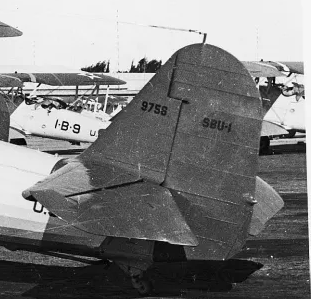
One of the more blatantly obvious inconsistencies found in the FSI plan is the shape of the rudder. The bloated profile is nowhere close to representing the true shape of the real thing. Compare the two pics below and you�ll see what I mean. But, as it is with most rubber powered models, oversize tail surfaces was/is common practice. We don�t want that.
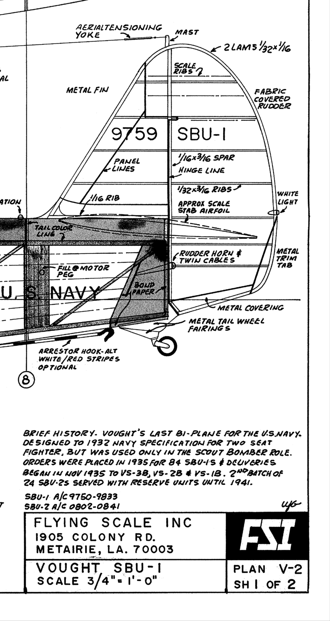 FSI rudder
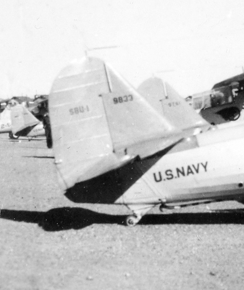 Actual rudder
But, I will give credit where it�s due as the v stab/rudder rib spacing in the FSI plan is pretty much to scale. Another noticeable detail of the FSI plan is the h stab/elevator angle of incidence. This too is quite apparent in the Vought 3 view. This angle was measured as roughly 2 degrees using CAD. After reading various pros and cons of horizontal stabilizer incidence, I chose not to design this 2 degrees into the h stab. Instead, it was designed with zero degrees incidence but adjustable to create the incidence if it is really needed. I could find no reference to airfoil type used for the SBU tail surfaces so NACA 0012 was chosen as the most probable type. So, armed with 3 view data and about two dozen pics for reference it was off the drawing board to make the plans.
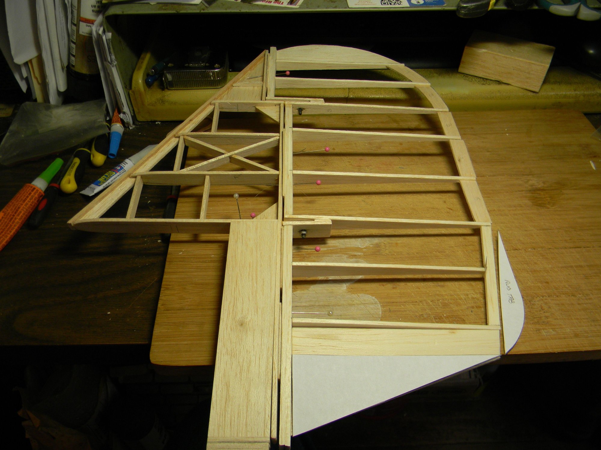
The first v stab/rudder prototype was built using soft balsa scraps. It was abandoned before completion due to several design flaws. After working out the bugs, a second prototype was built to completion.
 Prototype rudder
After proving the design adequate, the final version was built using �� basswood at all critical locations, hard balsa for ribs and short sections of 3/16� automotive brake line steel tubing as hinge point inserts. As it turned out, the brake line tubing inside diameter is a perfect fit for 4mm hinge bolts. You can see the bolts in position in the pic above and hinge point steel tubing insert in the pic below.
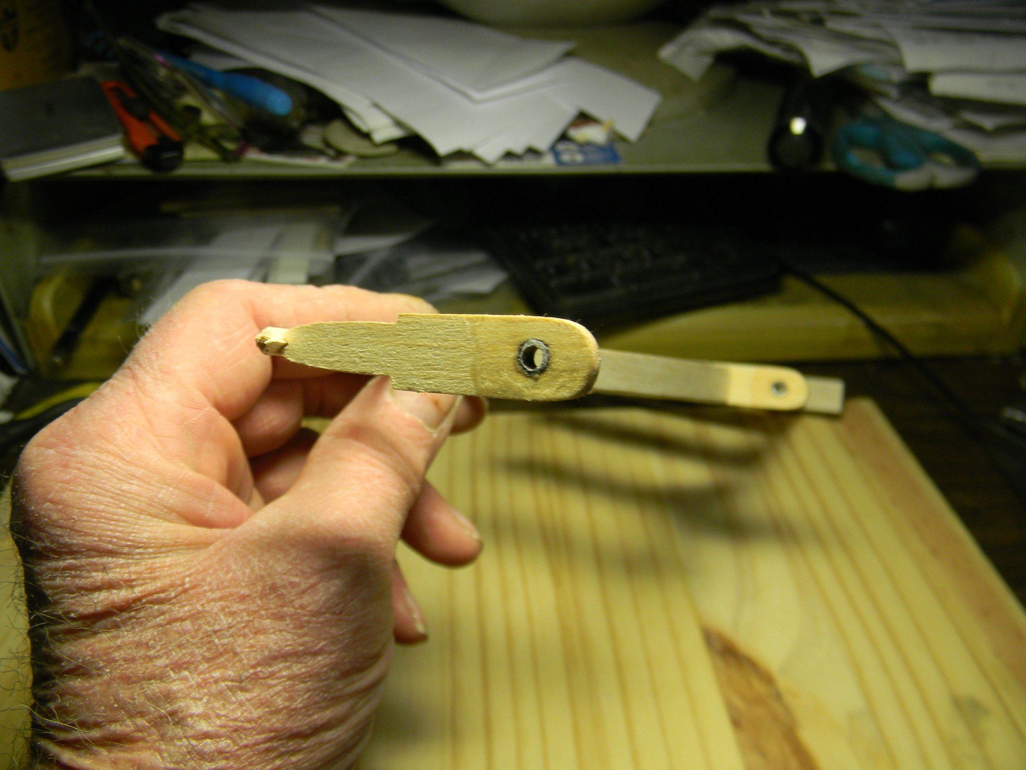 Steel tubing hinge point insert.
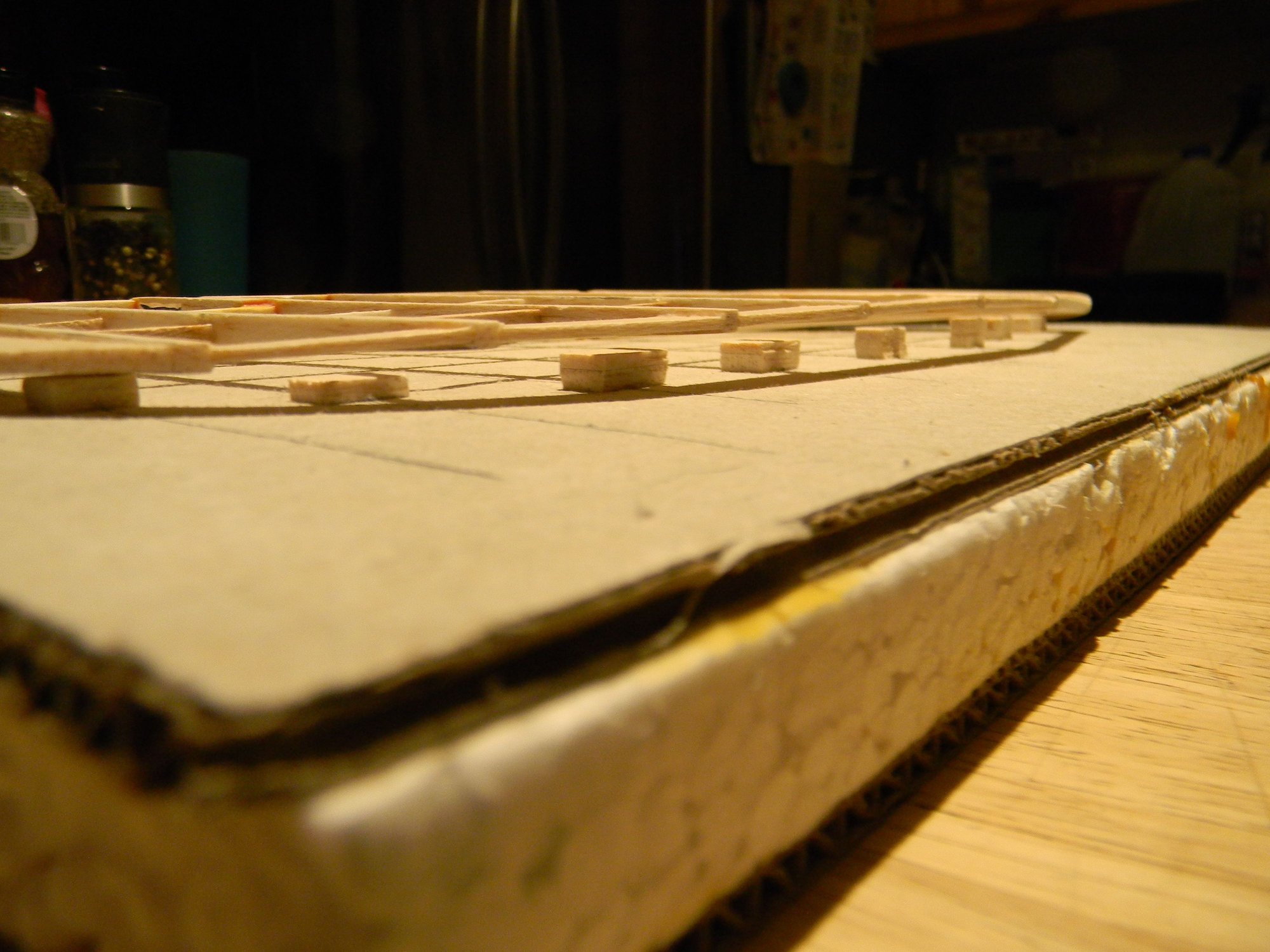
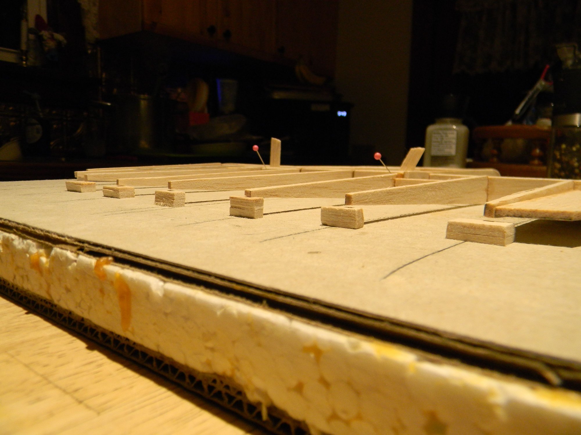
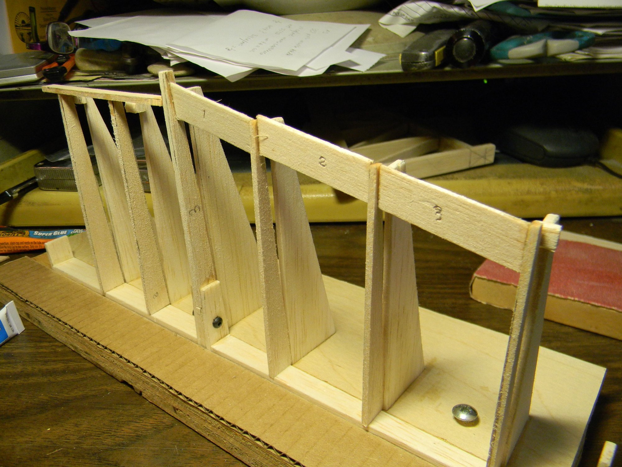
A quick and dirty jig was built to use for assembling the rudder.
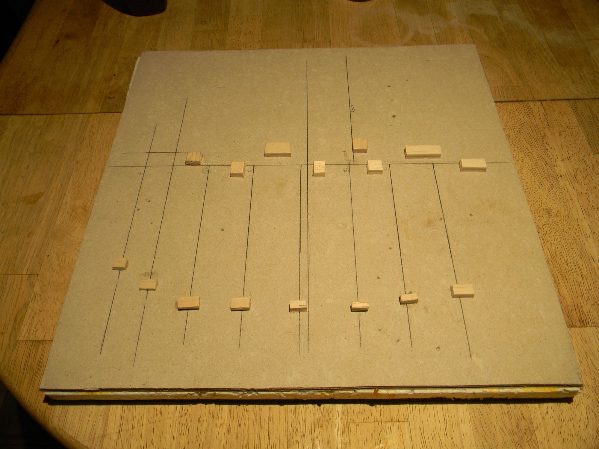 Rudder jig
Placing the prototype rudder on the jig quickly shows what happens when one tries to build something like this by eye only.
 Crooked 2nd prototype.
The jig worked as intended as the rudder built on it was straight and true in every aspect.
 Rudder ready for the trailing edge.
A housing whittled from a 3/8� hardwood dowel was added to the rudder trailing edge for a bright white LED to replicate the white nav light seen on a full size SBU tail Just above the rudder trim tab,
 SBU white nav light.
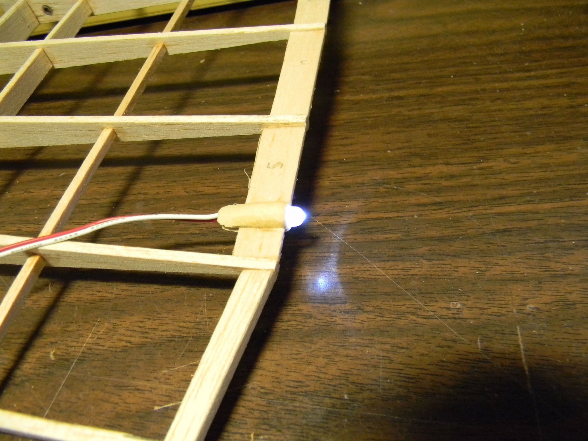 Bright white LED nav light.
Another quick and dirty jig was built for assembling the horizontal stabilizers. As with the v stab/rudder, all critical components are �� basswood with 1/8� hard balsa ribs and steel inserts at hinge points.
 H stab jig
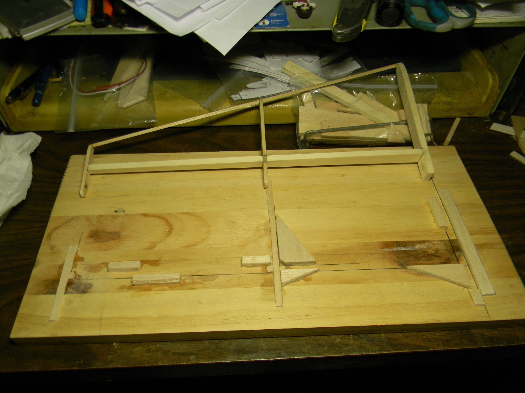
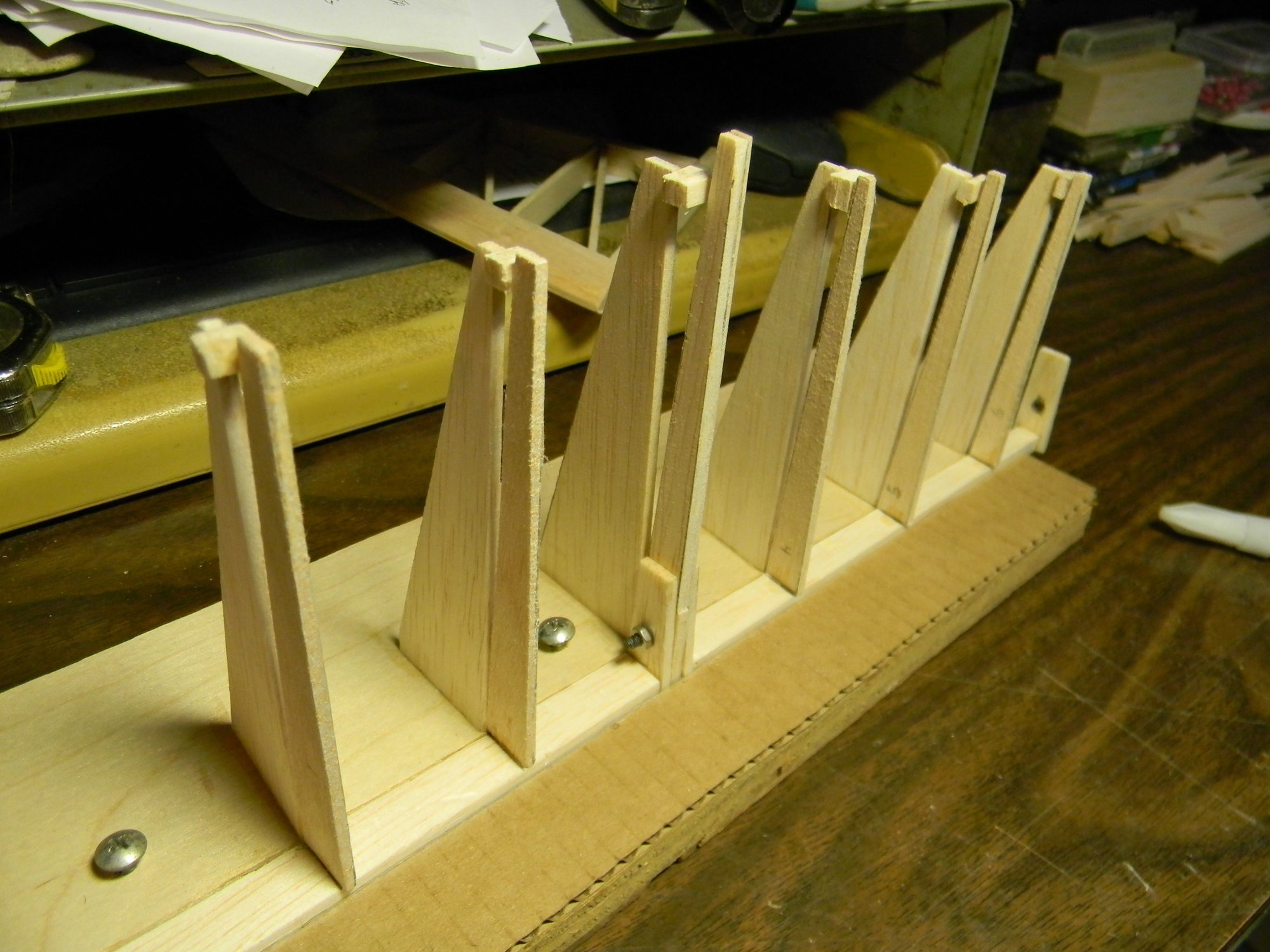
Another quick and dirty jig for building elevators was tossed together using scrap wood and cardboard. This one was not so user friendly but it produced matching elevators that are straight and true to form.
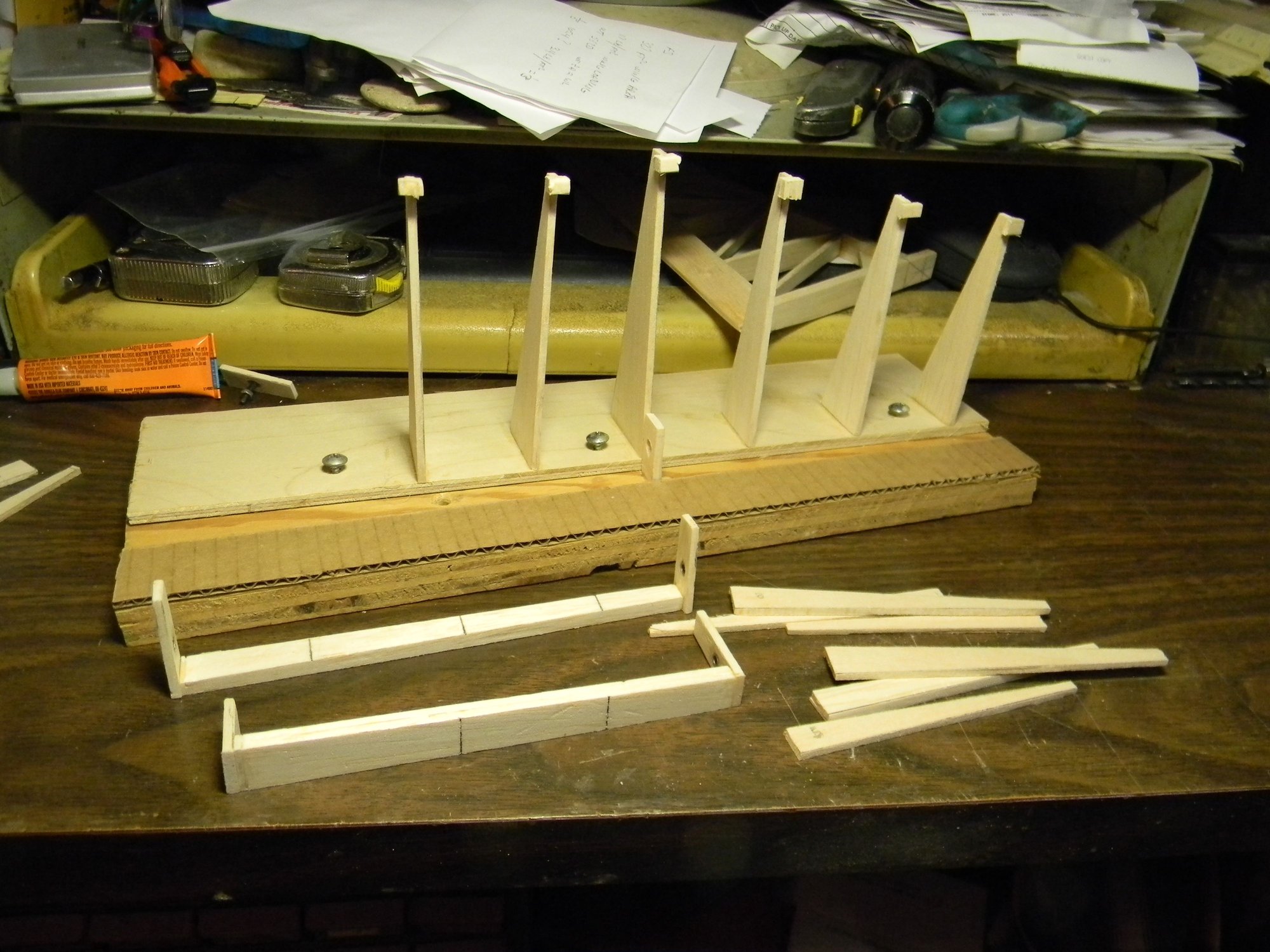 Elevator jig
 Ribs in place.
 Trailing edge installed.
A hardwood block (riser) was made to which the v stab/rudder and h stab/elevator is mounted. This block serves as the adjusting point should there be a need for h stab incidence. Everything was assembled to the riser then the riser was bolted to the fuse frame. A pull-pull cable was installed, and, as mentioned earlier the tail wheel gear was adjusted more toward vertical to the correct rudder control arm geometry. The pull-pull cables connect to the tail wheel gear control arm via ball links. A channel in the riser houses the elevator push rod which connects to the elevator control horn also with a ball link. The elevator control horn is silver soldered to a length of 10-32 all thread, which is epoxied to the elevator halves inside spruce blocks. The spruce blocks are also epoxied to the elevator halves. And, of course, the elevator halves were tuned to match each other before everything was epoxied in place.
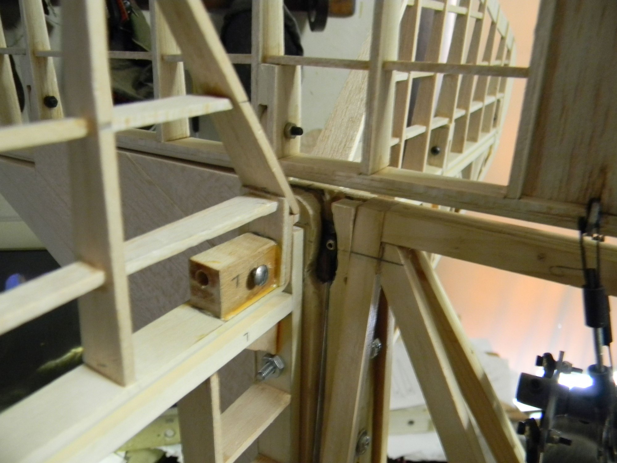 Elevator control linkage.
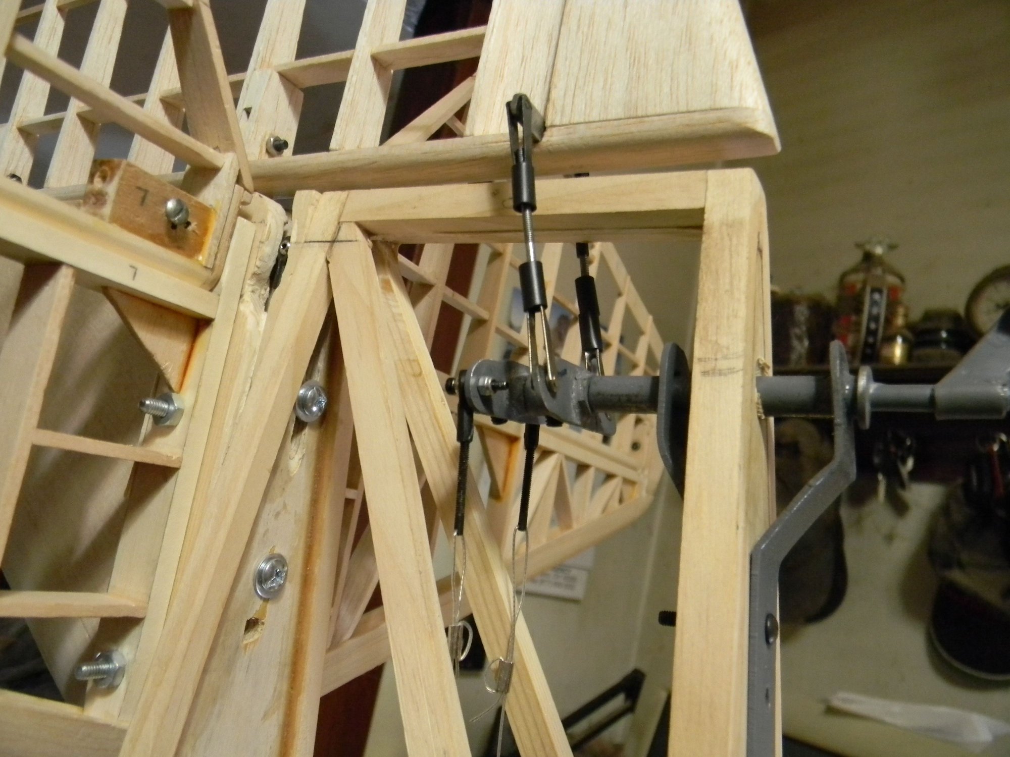 Rudder/tail wheel control linkage.
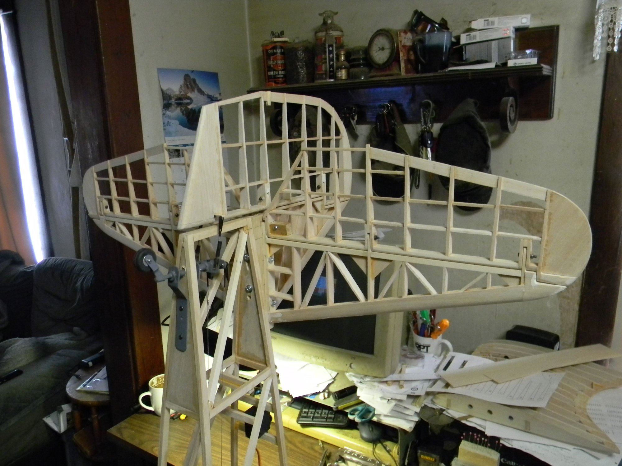 Empennage installed.
The fuse frame was set up and leveled to check side to side alignment of the h stab.
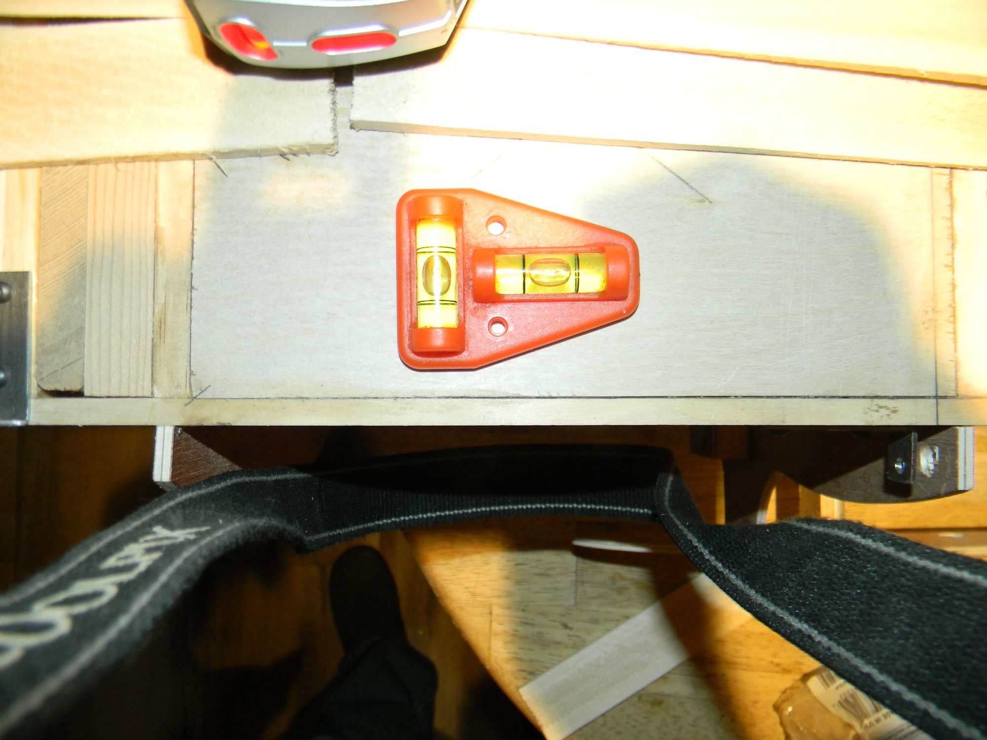 Fuse frame set up and leveled.
Alignment was checked using a laser level.
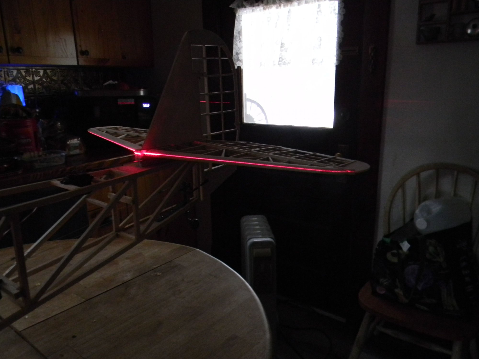 1/32" deviation side to side.
Starboard side stabilizer varies from port side about 1/32�. Not enough to worry about imo. I believe this tail assembly is a keeper. All that�s left to do here is covering and installing the trim tabs. Empennage weighs 11 ounces after sheeting the stabilizers. Next time we�ll look at building the lower wings. See you then.
Hank