Well, I finally decided to share my RAD project. I've been working on this for quite some time and am very happy with the results I am getting. The project started with a requirement for operation RADs in my model of the Queen of Chilliwack. All of the commercially available parts didn't fit my requirements. So I built my own RAD.
The RAD is machined out of 1/2" and 3/4" brass stock and the shafts and sleeves are dumas 1/8 drive shafts and sleeves. The gears are supplied by SDP-SI, as well as the belts. Servo is a Hitec Continuous rotation servo, and the magnetic potentiometer is supplied by US Digital.
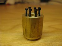
Lower gear casing. Those are #0 hex head cap screws, the pilot hole that was drilled for the thread tap was a 3/64" hole. The threads are so small that you can barely tell they are there.

Lower gear casing.

Lower gear casing.
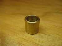
In hull mounted casing. (Fiberglassed into hull. Rad rotates inside the Tube.)

Upper Shaft Casing and through hull component.
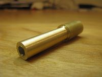
Upper Shaft Casing and through hull component.

Machining a part.

Rotating setup. Toothed timing belt on a continuous rotation servo with a 1/2 drive reduction.

Leg assembled and installed in hull.
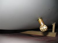
Leg assembled and installed in hull.

Leg assembled and installed in hull.
[link=http://s214.photobucket.com/albums/cc278/queenofchilliwack/Rads/?action=view¤t=Movie.flv]RADs in action[/link]
Cheers,