


Fully Operational Right Angle Drive
 02-11-2009 | 01:31 AM
#1
Thread Starter
Member
Joined: Aug 2007
Posts: 57
Likes: 0
Received 0 Likes
on
0 Posts
From: Chilliwack,
BC, CANADA
Well, I finally decided to share my RAD project. I've been working on this for quite some time and am very happy with the results I am getting. The project started with a requirement for operation RADs in my model of the Queen of Chilliwack. All of the commercially available parts didn't fit my requirements. So I built my own RAD.
The RAD is machined out of 1/2" and 3/4" brass stock and the shafts and sleeves are dumas 1/8 drive shafts and sleeves. The gears are supplied by SDP-SI, as well as the belts. Servo is a Hitec Continuous rotation servo, and the magnetic potentiometer is supplied by US Digital.
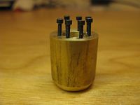
Lower gear casing. Those are #0 hex head cap screws, the pilot hole that was drilled for the thread tap was a 3/64" hole. The threads are so small that you can barely tell they are there.

Lower gear casing.

Lower gear casing.
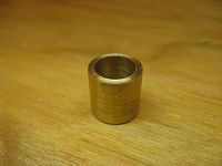
In hull mounted casing. (Fiberglassed into hull. Rad rotates inside the Tube.)

Upper Shaft Casing and through hull component.
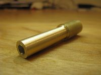
Upper Shaft Casing and through hull component.

Machining a part.

Rotating setup. Toothed timing belt on a continuous rotation servo with a 1/2 drive reduction.

Leg assembled and installed in hull.
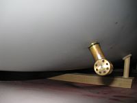
Leg assembled and installed in hull.

Leg assembled and installed in hull.
[link=http://s214.photobucket.com/albums/cc278/queenofchilliwack/Rads/?action=view¤t=Movie.flv]RADs in action[/link]
Cheers,
The RAD is machined out of 1/2" and 3/4" brass stock and the shafts and sleeves are dumas 1/8 drive shafts and sleeves. The gears are supplied by SDP-SI, as well as the belts. Servo is a Hitec Continuous rotation servo, and the magnetic potentiometer is supplied by US Digital.
Lower gear casing. Those are #0 hex head cap screws, the pilot hole that was drilled for the thread tap was a 3/64" hole. The threads are so small that you can barely tell they are there.
Lower gear casing.
Lower gear casing.
In hull mounted casing. (Fiberglassed into hull. Rad rotates inside the Tube.)
Upper Shaft Casing and through hull component.
Upper Shaft Casing and through hull component.
Machining a part.
Rotating setup. Toothed timing belt on a continuous rotation servo with a 1/2 drive reduction.
Leg assembled and installed in hull.
Leg assembled and installed in hull.
Leg assembled and installed in hull.
[link=http://s214.photobucket.com/albums/cc278/queenofchilliwack/Rads/?action=view¤t=Movie.flv]RADs in action[/link]
Cheers,

 02-11-2009 | 09:20 AM
#3
Junior Member
Joined: Feb 2009
Posts: 15
Likes: 0
Received 0 Likes
on
0 Posts
From: Cocoa, FL
Wow! I wish I still had my unimat lathe. I doubt I could create anything like this but would love to try. Can't wait to see the finished project.
02-11-2009 | 01:40 PM
#4

The video isn't working Cadmonkey...
I am guessing that the boat is using Azipods for propulsion.
The steering set up looks well done. Any hints on how you're
connecting to the motors? Drawings?
I was plotting how I could use Graupner drives to mimic the
azipods on the Bergensfjord boats. they are certainly capable of
rotating 360, but the Bergensfjord uses double ended drives...
I think the only concern is the black allen head screws that
you are using. Those things rust horribly. If you can find some
stainless steel screws, they will make your life easier should the
drives ever need to be disassembled for maintenance. [8D]
Ahh, got the videos off of the West Coast Ferries Forum ...
http://s214.photobucket.com/albums/c...t=MVI_0477.flv
Very nice...
http://s214.photobucket.com/albums/c...w¤t=Movie.flv
Also, your website seems to be down... www.queenofchilliwack.ca [ ]
]
I am guessing that the boat is using Azipods for propulsion.
The steering set up looks well done. Any hints on how you're
connecting to the motors? Drawings?
I was plotting how I could use Graupner drives to mimic the
azipods on the Bergensfjord boats. they are certainly capable of
rotating 360, but the Bergensfjord uses double ended drives...
I think the only concern is the black allen head screws that
you are using. Those things rust horribly. If you can find some
stainless steel screws, they will make your life easier should the
drives ever need to be disassembled for maintenance. [8D]
Ahh, got the videos off of the West Coast Ferries Forum ...
http://s214.photobucket.com/albums/c...t=MVI_0477.flv
Very nice...
http://s214.photobucket.com/albums/c...w¤t=Movie.flv
Also, your website seems to be down... www.queenofchilliwack.ca [
]
02-11-2009 | 06:16 PM
#5
Thread Starter
Member
Joined: Aug 2007
Posts: 57
Likes: 0
Received 0 Likes
on
0 Posts
From: Chilliwack,
BC, CANADA
Thanks guys,
The black screws are stainless steel. Its a lot of work to get these things going, such a pain in the @$$. The results are worth it though. When I am completly finished I will post some a full set of drawings so that anyone can build one if they want. I chose to go from solid brass stock as it is easy to machine yet still very strong. The only issues IU've had pertain tot he fact that the thing is about 7/8" long and 1.5" tall.
The Queen of Chilliwack has the exact same propulsion set up as the ship in those pictures Umi. I have 4 RADs, 2 at each end, with each end being independent of the other.
As for the website, its running on a POS computer in my basement, so I guess I'll have to take a look at it. I think my router has screwed up since our last power surge.
Cheers,
02-11-2009 | 09:17 PM
#6

Senior Member
Joined: Oct 2005
Posts: 232
Likes: 0
Received 0 Likes
on
0 Posts
From: Templeton,
CA
ORIGINAL: cadmunkey
When I am completly finished I will post some a full set of drawings so that anyone can build one if they want.
When I am completly finished I will post some a full set of drawings so that anyone can build one if they want.
I would certainly be interested in looking at a set of your drawings Cadmunkey.. very impressive work.
 02-15-2009 | 07:05 AM
#8
Senior Member
Joined: Mar 2007
Posts: 469
Likes: 0
Received 0 Likes
on
0 Posts
From: baltimore,
MD
i like your idea,but i would make sure that the drives are mounted parallel with the waterline as to not cause the boat to roll over by the thrust angle.this is a very good design by all means but i think you know what i am talking about.good luck with your new drive setups,also some streamlining is another thing to think about,a nosecone would make these more efficient.
tony p.
Gas Propulsion Systems.
Look for our new ready to race gas boats in the near future.guarantying 55mph out of the box performance,no assembly required
tony p.
Gas Propulsion Systems.
Look for our new ready to race gas boats in the near future.guarantying 55mph out of the box performance,no assembly required
02-15-2009 | 05:32 PM
#9
Thread Starter
Member
Joined: Aug 2007
Posts: 57
Likes: 0
Received 0 Likes
on
0 Posts
From: Chilliwack,
BC, CANADA
I don't want to seem like a jerk, but I have done a tonne of research on this ship, I have been given the privilege by her officers and crew as well as the managing company BCF to have any information I would like. I spent 3 days aboard her last summer and during that time I was allowed to take the helm and feel how she responds and is controlled. I was taken down into the bowels of the ship and was standing inside of the RAD housing and next to the engines. I can say I am quite the expert on the vessel with ease.
Of course any input is great, but I have seen how it works ont he real ship and would like to make myn work that way too.
Actually, the Rads in the real ship are mounted perpendicular to the hull NOT the waterline, of course they are perpendicular in to the waterline when facing backwards. When the RADs point along the axis of the hull IE. going straight they are perfectly lined up with the waterline, but when they are pushing sideways they are not perpendicular to the hull. It actually doesn't matter if the RADs are lined up with the waterline or not when going sideways, all of the forces will act around the ships center of gravity and will cause the same amount of roll as if they were lined up with the waterline, It will roll in any situation. You could argue that it would be more efficient to have the thrust vector line up with the waterline for more sideways speed, but not for roll.
Also, the ones int he real ship aren't streamlined so I don't want to make it untrue to the real vessel.
Just a couple of notes on the real Queen of Chilliwack as to help put the ships performance into respect.
-375'11" long, double ended, passenger/car ferry
-Class 1 icebreaker
-Built 1977 in Norway out of recycled naval vessels.
-4 1100HP 6 cyl. diesel engines at about 520 shaft RPM
-Maximum speed 14.2 knts
-Most efficient speed 10.8 knts on rear 2 engines at about 60% power each - forward 2 RADs freewheeling with engines off and disengaged.
You can see that the ship is a pig, its not a performance vessel of any sort. Already from the, little time I have had the one RAD operational in the hot tub I have found her to have comparable power to the real ship, and of course on only one RAD. She will be quite powerful once all 4 RADs are completed. And when I do there will be footage and pics to share.
Cheers,
04-06-2009 | 09:20 PM
#10
Thread Starter
Member
Joined: Aug 2007
Posts: 57
Likes: 0
Received 0 Likes
on
0 Posts
From: Chilliwack,
BC, CANADA
Well, I finally have the No. end RADs complete. Not a very easy thing to build, it takes quite some time to get the gear to mesh nicely. I don't have a CNC or a very nice lathe so My tolerances are quite high. So everything has to be tweaked when assembled.
[link=http://s214.photobucket.com/albums/cc278/queenofchilliwack/Rads/?action=view¤t=Movie_0002.flv]Video of RADs Operating[/link]
Cheers,
[link=http://s214.photobucket.com/albums/cc278/queenofchilliwack/Rads/?action=view¤t=Movie_0002.flv]Video of RADs Operating[/link]
Cheers,
 04-22-2009 | 01:19 AM
#14
Thread Starter
Member
Joined: Aug 2007
Posts: 57
Likes: 0
Received 0 Likes
on
0 Posts
From: Chilliwack,
BC, CANADA
I'm trying to design some sort of a dial system, but it is not a simple task. For know I will just have to pay attention and guess where they are.
My website is back up and running.
cheers,
My website is back up and running.
cheers,
04-30-2009 | 11:18 PM
#15
Thread Starter
Member
Joined: Aug 2007
Posts: 57
Likes: 0
Received 0 Likes
on
0 Posts
From: Chilliwack,
BC, CANADA
Tonight I tested the ship in the hot-tub with all 4 RADs. They worked great, but that wasn't enough for me. So, me and my brother took her to the city pond. The lily pad flowers were a pain but if I could avoid them I got to see her true power and maneuverability. I am very happy with her. She is very hard to control with the current setup, but should be better after the computer system is built in the future. Ohh yeah, she doesn't leak either.
The very first footage of her on the open water.
[link=http://s214.photobucket.com/albums/cc278/queenofchilliwack/Videos/?action=view¤t=OpenWater.flv]Operational Video[/link]
The very first footage of her on the open water.
[link=http://s214.photobucket.com/albums/cc278/queenofchilliwack/Videos/?action=view¤t=OpenWater.flv]Operational Video[/link]
 05-01-2009 | 12:21 PM
#17
Cadmunkey.
You have it running really nice.
[8D][8D][8D]
Here's a couple pics of Leen Boers' drive controls.
I his boat and controls while touring Madurodam.
Not sure how he set this up.
Throttle and steering are the two top right hand controls.
Wire controls throttel F/R, twist the knob and it steers the drives.
06-07-2009 | 02:09 AM
#18
Thread Starter
Member
Joined: Aug 2007
Posts: 57
Likes: 0
Received 0 Likes
on
0 Posts
From: Chilliwack,
BC, CANADA
Well, it was noted today at the northwest reaggatta that I had not show any video of the completed RADs operating from a mechanical standpoint. Both of these clips are of the No. 1 end RADs.
s214.photobucket.com/albums/cc278/queenofchilliwack/Rads/
And the very early stages of programing and creating a proper control system.
s214.photobucket.com/albums/cc278/queenofchilliwack/Rads/
Cheers,
s214.photobucket.com/albums/cc278/queenofchilliwack/Rads/
And the very early stages of programing and creating a proper control system.
s214.photobucket.com/albums/cc278/queenofchilliwack/Rads/
Cheers,
 07-24-2009 | 01:33 AM
#20

Very nice, love to see the machine work of others.
You just cant beat what a lathe, mill, sweat, blood and imagination can bring to our hobby.
You just cant beat what a lathe, mill, sweat, blood and imagination can bring to our hobby.
10-31-2009 | 07:35 PM
#22

Joined: Mar 2007
Posts: 267
Likes: 0
Received 0 Likes
on
0 Posts
From: Hamilton, ON, CANADA
Sorry if this is a repeat question.
Has there been schematic drawings of the drive mechanism posted yet ? I did not see them here.
Would like to try to build myself a small pair as well, if possible with my lathe experience.
Thanks, George
Has there been schematic drawings of the drive mechanism posted yet ? I did not see them here.
Would like to try to build myself a small pair as well, if possible with my lathe experience.
Thanks, George


