


Incidence problems using Robart incidence meter
 07-20-2015 | 11:34 AM
#1

Hello,
I'm having trouble using the Robart Incidence meter.
I'm building a Sig Hog Biplane and the plans call for both wings to have a zero degree incidence relative to the datum plane.
I drew the datum line on the side of the fuselage and then leveled the line on a Robart stand.
With the fuselage upside down, I mounted the bottom wing and rechecked that the fuse was level.
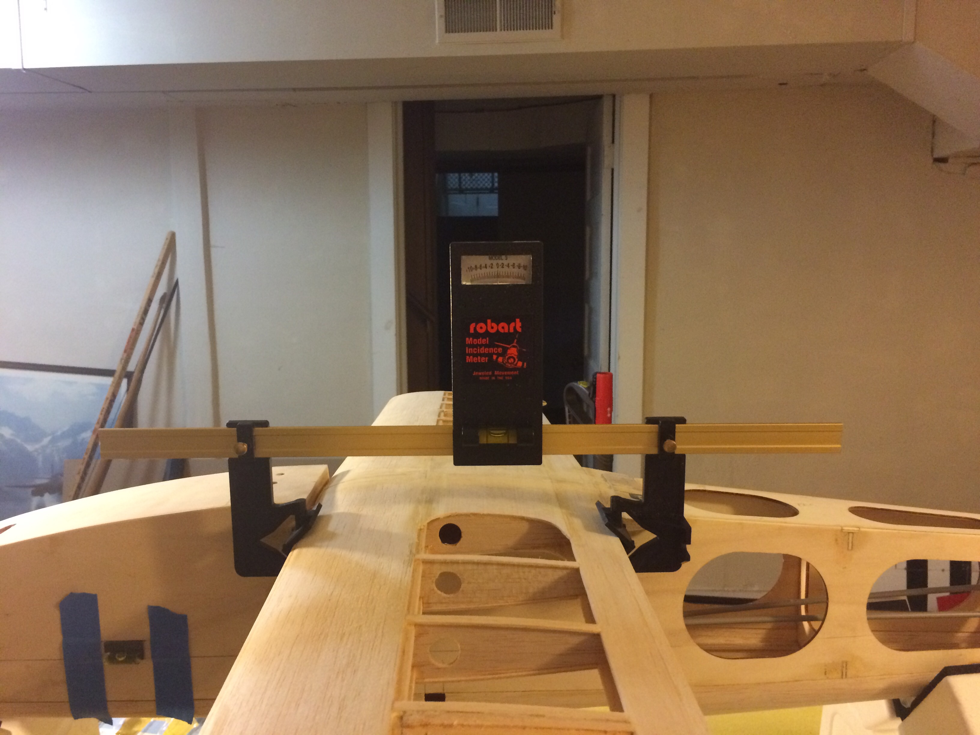
Next I mounted the incidence meter on the right wing facing the wingtip and on the left wing facing away from the wing tip.
In both readings the meter is facing towards me when standing by the right wing.
In both cases the meter read zero.
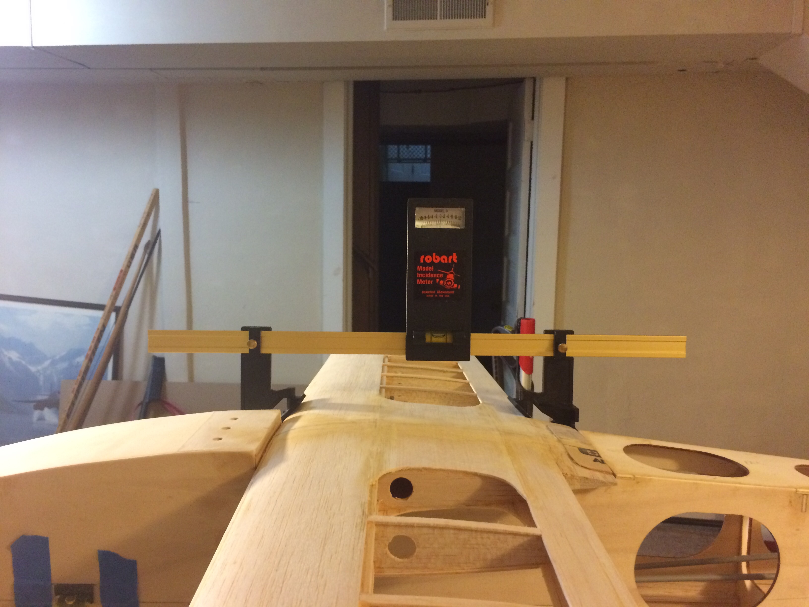
Now when I switch the meter around so it's facing away from the right wingtip, it reads between -.25 to -.5 degrees incidence.
My question is, which reading is correct? If I go with the -.25 to -.5 the. I need to shim up the trailing edge to get to zero.
If I use the zero reading then I'm good and don't need to do anything.
Is this close enough for a non precision sport plane? Should I just test fly it and see if it needs adjusting? Sounds like I might have some wing warpage. But before I start shimming/sanding to get the incidence right, I want to make sure I have the correct reading.
Thanks for the help! I hope my question was not to confusing.
-Matt
I'm having trouble using the Robart Incidence meter.
I'm building a Sig Hog Biplane and the plans call for both wings to have a zero degree incidence relative to the datum plane.
I drew the datum line on the side of the fuselage and then leveled the line on a Robart stand.
With the fuselage upside down, I mounted the bottom wing and rechecked that the fuse was level.
Next I mounted the incidence meter on the right wing facing the wingtip and on the left wing facing away from the wing tip.
In both readings the meter is facing towards me when standing by the right wing.
In both cases the meter read zero.
Now when I switch the meter around so it's facing away from the right wingtip, it reads between -.25 to -.5 degrees incidence.
My question is, which reading is correct? If I go with the -.25 to -.5 the. I need to shim up the trailing edge to get to zero.
If I use the zero reading then I'm good and don't need to do anything.
Is this close enough for a non precision sport plane? Should I just test fly it and see if it needs adjusting? Sounds like I might have some wing warpage. But before I start shimming/sanding to get the incidence right, I want to make sure I have the correct reading.
Thanks for the help! I hope my question was not to confusing.
-Matt
Last edited by Flyboywbl; 07-20-2015 at 11:47 AM.
 07-20-2015 | 11:35 AM
#2
Mounted this way it reads between -.25 and .5 degrees. I know it's hard to see the degree reading in the picture but you can tell that the bubble level is off in the second set of pictures. In this case, I would have to shim the trailing edge up to get it back to level with the datum plane.
Last edited by Flyboywbl; 07-20-2015 at 11:48 AM.
07-20-2015 | 12:00 PM
#3


My Feedback: (5)
I use the Robart meter all the time. Keep in mind that the original Astro Hog did not have a symmetrical airfoil. It may have been a NACA 2415. If Sig has continued with that it will effect the readings you get depending on how you mount the meter. I think your readings are good for a sport plane and represent the care you have put in to the build. Dan.
07-20-2015 | 12:10 PM
#4
Thanks Dan,
Question though, wouldn't the chord line be exactly the same either way you mount the meter? In that case I should be getting the same reading wheather the meter faces the wing root or wing tip. Maybe -.25 degrees is splitting hairs in a sport plane. I built the Hog Bipe back in 2006 and did not use an incidence meter. It was only my second kit and it was warped every which way. I thought it flew great.
i'm just a sport, non competitive, aerobatic pilot so I'm not looking for excellence.
-Matt
Last edited by Flyboywbl; 07-20-2015 at 12:15 PM.
07-20-2015 | 12:43 PM
#5


I would check the meter on some other shape than a wing and do this same flip to see if the readings are identical. And try it on a few different thicknesses. If the jaws do not have extactly matching V's then this much difference might well be the case. Do the tests on something very firmly held too so you know it's not shifting around.
Assuming it's the jaws that are causing the difference the actual reading will be the average of the difference. So your true wing angle is between -0.125� and -0.25� so call it around -0.18�. And I'd suggest that if you're not flying at some world championship level that this will be close enough.
Assuming it's the jaws that are causing the difference the actual reading will be the average of the difference. So your true wing angle is between -0.125� and -0.25� so call it around -0.18�. And I'd suggest that if you're not flying at some world championship level that this will be close enough.
07-20-2015 | 01:10 PM
#6
My Feedback: (5)
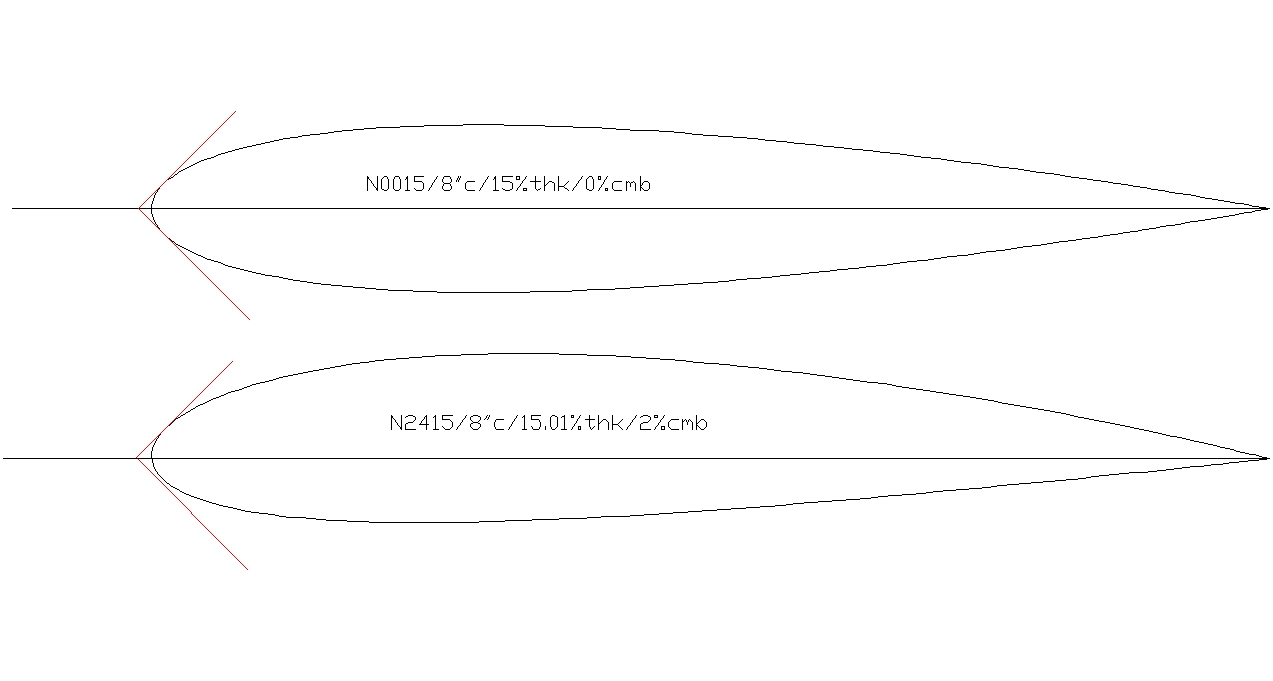
Those end pieces on the meter do not engage the leading and trailing edges of the airfoil the same for a symmetrical airfoil as a non-symmetrical airfoil the same way You can see the difference in this drawing. The difference is minor and I always ignore it. I set up all my planes at 0-0-0 for everything and use the moveable surfaces to trim it out. I fly like you do. I takeoff, fly in circles and land. If I land without any damage, it turns me on. Dan
07-20-2015 | 01:37 PM
#7
My Feedback: (3)
I agree with the others that you're close enough as is and you're doing the right thing in taking all the measurements with the meter facing the same direction so that the readings are consistent. If you want to double check the incidence and/or calibrate your Robart meter for future reference, measure off your bench top to the center of the leading edge and to the trailing edge (the difference being side a), and the cord of the wing where you took the measurements (side c), or the horizontal distance between the leading edge and trailing edge measurements (side b), and plug them into one of the many Right Triangle calculators available on-line.
07-20-2015 | 06:22 PM
#9

My Feedback: (26)
I had the same experience with my Robart meter. I never could determine what it was on the meter that causes it. Like you I take all the measurements with the meter facing the same direction so that the readings are consistent. I think your wing is setup good enough. Finish it and have fun flying it.
07-21-2015 | 03:57 AM
#11
Joined: Jan 2015
Posts: 280
Likes: 0
Received 0 Likes
on
0 Posts
First it looks like the bubble may not be centered
the same in all pictures.
Second the numbers and lines on the scale
may not be centered properly in the meter.
You can check this by making the rail level
on a flat surface. Use a stack of (razor blades
or something similar)under each end of the rail.
Adjust the number of blades on each side until
it is level. Once it is, turn the rail around and
see if the reading is the same. If it isn't you may
be able to take the thing apart and move the
numbers to where they belong.
If this checks out, do the same thing using the
wing clamp things to check the incidence of
a piece of window glass or flat metal. If it
is not the same both ways, you can file one
or both rail slots and shim them to hold the
rail in the proper position.
The final alternative is to always use the
incidence meter facing the same way.
The incidence angles are only important
in relation to other incidence angles, such
as top and bottom wing, or wing and tail.
If they are all wrong by the same amount
in the same direction, it is as good as right.
Jenny
ps Before you get your panties in a knot,
yes, thrust angle does relate to the incidence
angles, but it is usually a separate issue
more related to CG, weight, and speed
and drag. So, it is adjusted after the plane
is done and flying.
And no, the "incidence" of the fuselage
doesn't make that much difference.
Maybe a little, but mostly it is not enough
to warrant much attention.
Last edited by Jennifer Curtis; 07-21-2015 at 04:20 AM.
07-21-2015 | 04:59 AM
#12
My Feedback: (84)
Joined: Jan 2002
Posts: 46
Likes: 0
Received 0 Likes
on
0 Posts
From: Sarasota,
FL
There is one important thing to know about wing incidence in a Positive Stagger Bi Plane, that is, the Top Wing is forward of the Bottom Wing. In this situation it is critical, especially in Scale Airplanes and Full Scale, that the Upper Wing is placed at a Higher incidence than the Lower Wing. This will insure that the Upper Wing stalls before the Lower Wing. If the Lower Wing were to stall before the Upper Wing you would have an uncontrollable aircraft with an aft CG. However, in a Sport Scale Lightly Loaded Bipe, such as the Hog, I would not think it would matter much.
07-21-2015 | 05:31 AM
#13
Joined: Jan 2015
Posts: 280
Likes: 0
Received 0 Likes
on
0 Posts
There is one important thing to know about wing incidence in a Positive Stagger Bi Plane, that is, the Top Wing is forward of the Bottom Wing. In this situation it is critical, especially in Scale Airplanes and Full Scale, that the Upper Wing is placed at a Higher incidence than the Lower Wing. This will insure that the Upper Wing stalls before the Lower Wing. If the Lower Wing were to stall before the Upper Wing you would have an uncontrollable aircraft with an aft CG. However, in a Sport Scale Lightly Loaded Bipe, such as the Hog, I would not think it would matter much.
wing is stalled, to a point.
jenny
07-21-2015 | 07:18 AM
#14

This is the best thing stated by Jennifer, been doing just that for years.
The final alternative is to always use the
incidence meter facing the same way.
The incidence angles are only important
in relation to other incidence angles, such
as top and bottom wing, or wing and tail.
If they are all wrong by the same amount
in the same direction, it is as good as right.
Bob
The final alternative is to always use the
incidence meter facing the same way.
The incidence angles are only important
in relation to other incidence angles, such
as top and bottom wing, or wing and tail.
If they are all wrong by the same amount
in the same direction, it is as good as right.
Bob
Last edited by sensei; 07-21-2015 at 07:21 AM.
07-21-2015 | 11:52 AM
#15
Joined: Jul 2014
Posts: 25
Likes: 0
Received 0 Likes
on
0 Posts
This is the best thing stated by Jennifer, been doing just that for years.
The final alternative is to always use the
incidence meter facing the same way.
The incidence angles are only important
in relation to other incidence angles, such
as top and bottom wing, or wing and tail.
If they are all wrong by the same amount
in the same direction, it is as good as right.
Bob
The final alternative is to always use the
incidence meter facing the same way.
The incidence angles are only important
in relation to other incidence angles, such
as top and bottom wing, or wing and tail.
If they are all wrong by the same amount
in the same direction, it is as good as right.
Bob
 Like Jenny said, it's all relative.
What may also be of interest is that a .25 degree error is only .004" per inch of chord. So how bad is it really?
And finally, all this checking; left, right, reversed left, right is simply telling you more about artichokes than you need to know about squirrels. If you're comfortable that the wing is true, in and of itself, then cover the bird and let us know how she performs in the air. My guess at this point is that she'll be just fine.
08-18-2015 | 09:21 AM
#16
Joined: Dec 2007
Posts: 465
Likes: 0
Received 0 Likes
on
0 Posts
From: Upstate NY although I often wonder why...
No arguments with any of the above.
The needle on the scale on my meter broke/bent. I never liked trying to read it anyway. So I went to Harbor Freight and bought a digital carpenters angle gauge. By gluing a piece of 1/4 inch plywood on the shelf above the bubble level on the Robart meter, I was able to set the angle gauge on top of it and get a nice, easy, digital readout.
To make sure it was accurate, I set the rail of the Robart on top of a long level (that I know is good) and let it calibrate to zero. Subsequent measurements are very repeatable to...so I like it.
I most recently used it on an Ultrasport. The horizontal stab was already glued in place and while I was pretty confident it was on straight etc. the fact of the matter is it was where it was going to stay. So, the neat thing about the digital angle gauge is that it has a button to calibrate to zero, and once it is calibrated it takes all subsequent measurements to that newly acquired reference. This is very convenient because you don't have to spend time getting the fuse to an exact level position. Just block it up close by eye...put the angle guage on the stab and let it calibrate that as zero. It doesn't matter if the stab isn't perfect at that point because subsequent readings on the wing are relative to the tail calibration.
I slide the meter to the wing and get a digital measurement of incidence relative to the tail...it is always easier to move the wing saddle up and down a touch than it is a stab that is already glued in place!
In the end though, as accurate as I try to be, the error seems to come from the Robart brackets and how they attach to different shapes. So, I don't get too nuts about it and my guess is close is good enough.
As others have said as long as it is good relative to eachother; its good.
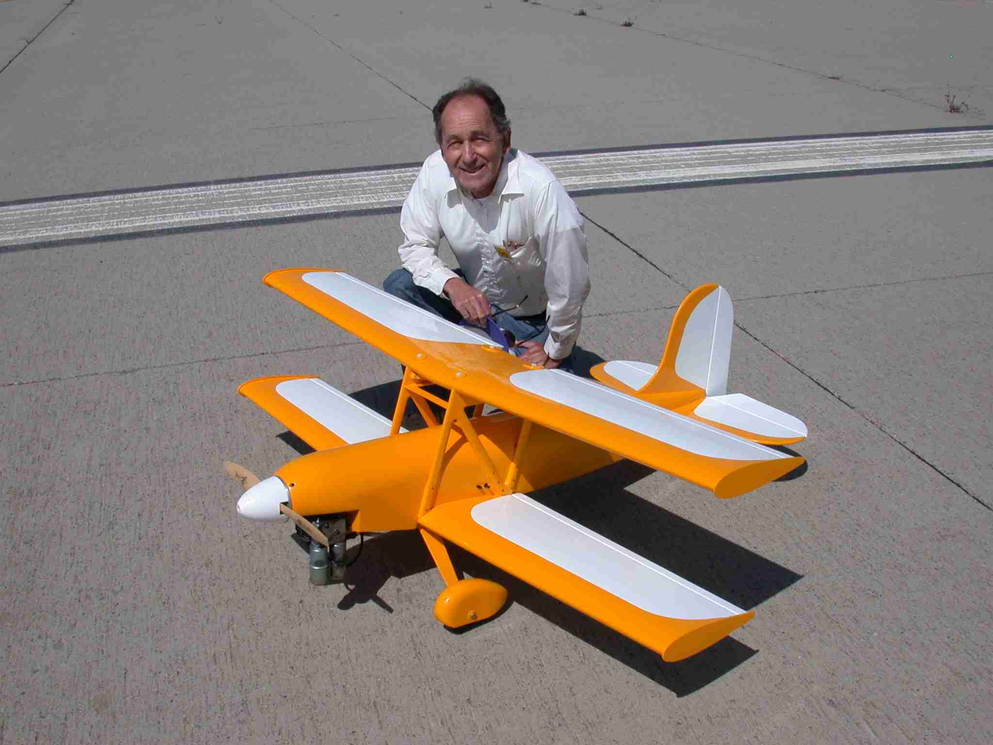
Great looking plane you have there and I hope you are having fun with it!
Tom
The needle on the scale on my meter broke/bent. I never liked trying to read it anyway. So I went to Harbor Freight and bought a digital carpenters angle gauge. By gluing a piece of 1/4 inch plywood on the shelf above the bubble level on the Robart meter, I was able to set the angle gauge on top of it and get a nice, easy, digital readout.
To make sure it was accurate, I set the rail of the Robart on top of a long level (that I know is good) and let it calibrate to zero. Subsequent measurements are very repeatable to...so I like it.
I most recently used it on an Ultrasport. The horizontal stab was already glued in place and while I was pretty confident it was on straight etc. the fact of the matter is it was where it was going to stay. So, the neat thing about the digital angle gauge is that it has a button to calibrate to zero, and once it is calibrated it takes all subsequent measurements to that newly acquired reference. This is very convenient because you don't have to spend time getting the fuse to an exact level position. Just block it up close by eye...put the angle guage on the stab and let it calibrate that as zero. It doesn't matter if the stab isn't perfect at that point because subsequent readings on the wing are relative to the tail calibration.
I slide the meter to the wing and get a digital measurement of incidence relative to the tail...it is always easier to move the wing saddle up and down a touch than it is a stab that is already glued in place!
In the end though, as accurate as I try to be, the error seems to come from the Robart brackets and how they attach to different shapes. So, I don't get too nuts about it and my guess is close is good enough.
As others have said as long as it is good relative to eachother; its good.
Great looking plane you have there and I hope you are having fun with it!
Tom
04-09-2016 | 04:57 AM
#17
Senior Member
Joined: Dec 2010
Posts: 210
Likes: 0
Received 0 Likes
on
0 Posts
From: merrill, WI
symmetrical or non-symmetrical, or flat bottom or not, there should no difference in the reading when you flip the meter end for end on the wing, as long as the initial set up of the meter is done correctly and both attachment brackets are identical in all aspects. if you are getting different readings, your level is not set exactly right or there is a difference in the shape of the "V" in the attachment brackets. one other spot to check is that there is no play where the attachment arms mount to the beam. if play exists there, it changes the relationship "V" to datum by changing the included angle of the "V" in relation to the wing's chord line.


