


Pulse 125 Pilot Size
 11-26-2013 | 08:38 AM
#26


It took me quite a while to get it in the right place. I have had the cowl on with the mounts in place, but with the engine now mounted, I won't be able to tell if it changes anything. It shouldn't, but it is my next step. First, I will be measuring the distance from the exhaust port to the cowl inside wall. I am trying to determine if the j-tec wrap around pitts muffler will fit. If the distance is too small, I will see if they can custom build one with a narrower exhaust box on the side. I don't mind spending the bucks if I an get one to fit.
 11-29-2013 | 09:05 AM
#27
Took the plunge and ordered the compact canister Pitts style muffler from J-tec. While waiting, I decided it was time to set up the fuel line, choke, and throttle servo. I have drilled the firewall for all three, installed the throttle servo, and am working on the choke linkage. I will post the pics when completed. To avoid the interference from the fuel tank, I have moved it back from the firewall, and placed the servo and choke linkage just behind the firewall. The choke will be a manual lever using 1/2 of a servo horn and after installing it, I did have to increase the size of the hole in the firewall. No big deal, and it now looks like a keyhole. Will finish up the connections tomorrow or next day.


Last edited by hookedonrc; 11-29-2013 at 02:19 PM.
11-30-2013 | 12:25 PM
#28
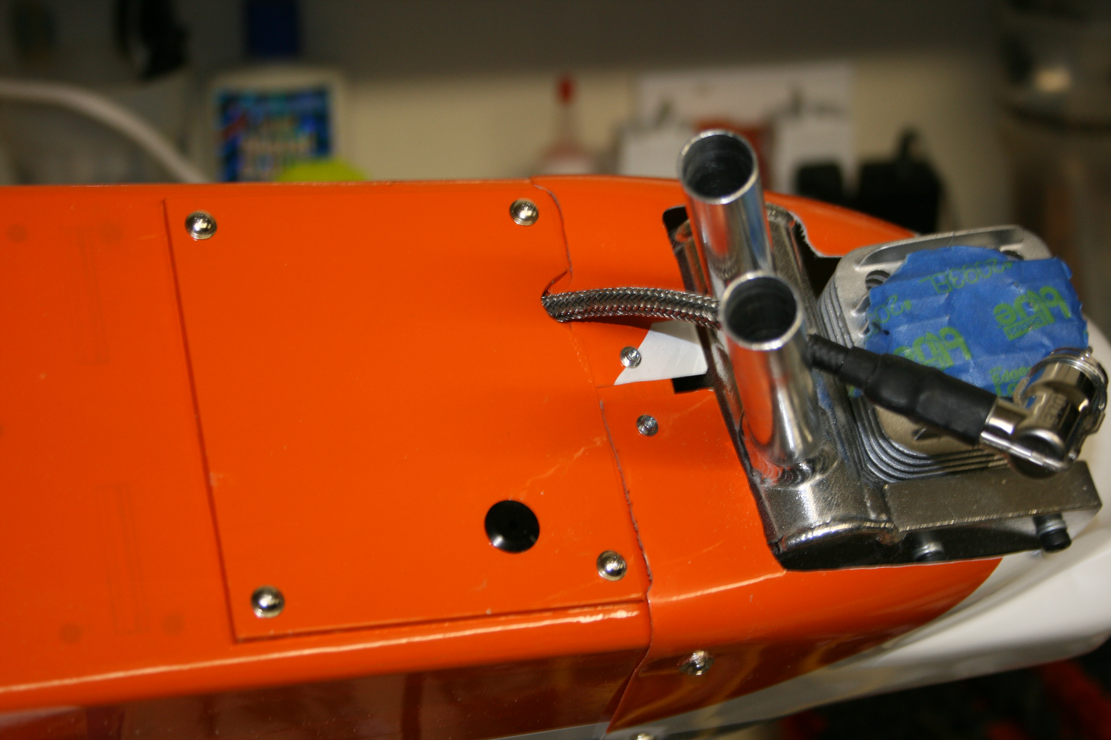
OK, once I started on this puppy, I made a conscious decision to try and keep it as neat on the outside as I could. No rod extensions outside, a full cowl except for engine head and exhaust. According to J-tec and tailskid, it should be doable. Per my previous post and pics, I am working on the install of the throttle servo, and manual choke mechanism. Well after quite few hours at the bench yesterday and today, I can report success. There was more grinding and drilling than in my Dentist's office, but, I have the throttle connected, and the manual mechanism for the choke in place. The only outside item will be the manual choke, which I chose to have exit on fuselage right. I am comfortable with that and it works great....full open and full closed without running into anything....that's where the grinding and drilling came from. I will have to remove everything one more time...(well I know it will probably be more...) to add thinned epoxy to the firewall, add CA to some of the screw holes I made, but after removing the engine at least 4-6 times today for the choke, I am pretty sure it will not be that many.
Without further descriptions, here are the pics...2 from inside the firewall, 2 from outside (showing choke fully open and fully closed) and 1 showing the choke lever exit. I haven't cleaned up the choke lever yet, just haven't decided what I want to do on it.


Without further descriptions, here are the pics...2 from inside the firewall, 2 from outside (showing choke fully open and fully closed) and 1 showing the choke lever exit. I haven't cleaned up the choke lever yet, just haven't decided what I want to do on it.
Last edited by hookedonrc; 11-30-2013 at 12:31 PM.
12-02-2013 | 08:35 AM
#29
grosbeak, tailskid... I need help on the spinner for the 3 bladed prop. I have found the spinner.... http://www3.towerhobbies.com/cgi-bin...?&I=LXLW21&P=7
It's the Tru-turn standard 3 blade spinner. Problem is I don't know what lock nut adapter to get for it. I have looked through the list, but DLE engines are not listed. Do either of you know which adapter I should use?
It's the Tru-turn standard 3 blade spinner. Problem is I don't know what lock nut adapter to get for it. I have looked through the list, but DLE engines are not listed. Do either of you know which adapter I should use?
12-02-2013 | 09:52 AM
#30

Senior Member
grosbeak, tailskid... I need help on the spinner for the 3 bladed prop. I have found the spinner.... http://www3.towerhobbies.com/cgi-bin...?&I=LXLW21&P=7
It's the Tru-turn standard 3 blade spinner. Problem is I don't know what lock nut adapter to get for it. I have looked through the list, but DLE engines are not listed. Do either of you know which adapter I should use?
It's the Tru-turn standard 3 blade spinner. Problem is I don't know what lock nut adapter to get for it. I have looked through the list, but DLE engines are not listed. Do either of you know which adapter I should use?
Do you have an LHS? I suggest you visit with your spinner and engine to find a match.
12-02-2013 | 10:08 AM
#31
I wish we had an LHS...we do have hobby town in Tulsa, I could try them. It is the adaptor kit I am concerned about. I can get the spinner from tru-turn, or Dave Brown, the issue is the adaptor kit for the shaft on the engine. I did try one I used on another motor that I had in my spare parts drawer and it didn't fit. I am going with the 15X7 Master Airscrew 3 bladed prop.
Thanks....
Thanks....

 01-07-2014 | 07:46 AM
#35
For anyone wondering about my progress, I have has 2 issues. First, has been parts. I am at the point of doing the cowl mods to fit it around the engine, I ordered and received a J-tec wrap around Pitts style muffler which required slight modification to the mount. Also have on order, but not received is a Tru Turn spinner for the 15x7 MAS prop I am going to use. And finally, I caught bronchitis so bad I have been out of commission for over a month. Hope to get back to working soon. Write up and pics to come.
01-19-2014 | 09:57 AM
#36
Well not Dentistry exactly, but I always feel like one when I do a lot of Dremel work. I am back at work after 2 months of bronchitis or something...lungs burn terribly when breathing cold air. I still have it somewhat, but I can't stay out of the garage either...don't care how cold it is.
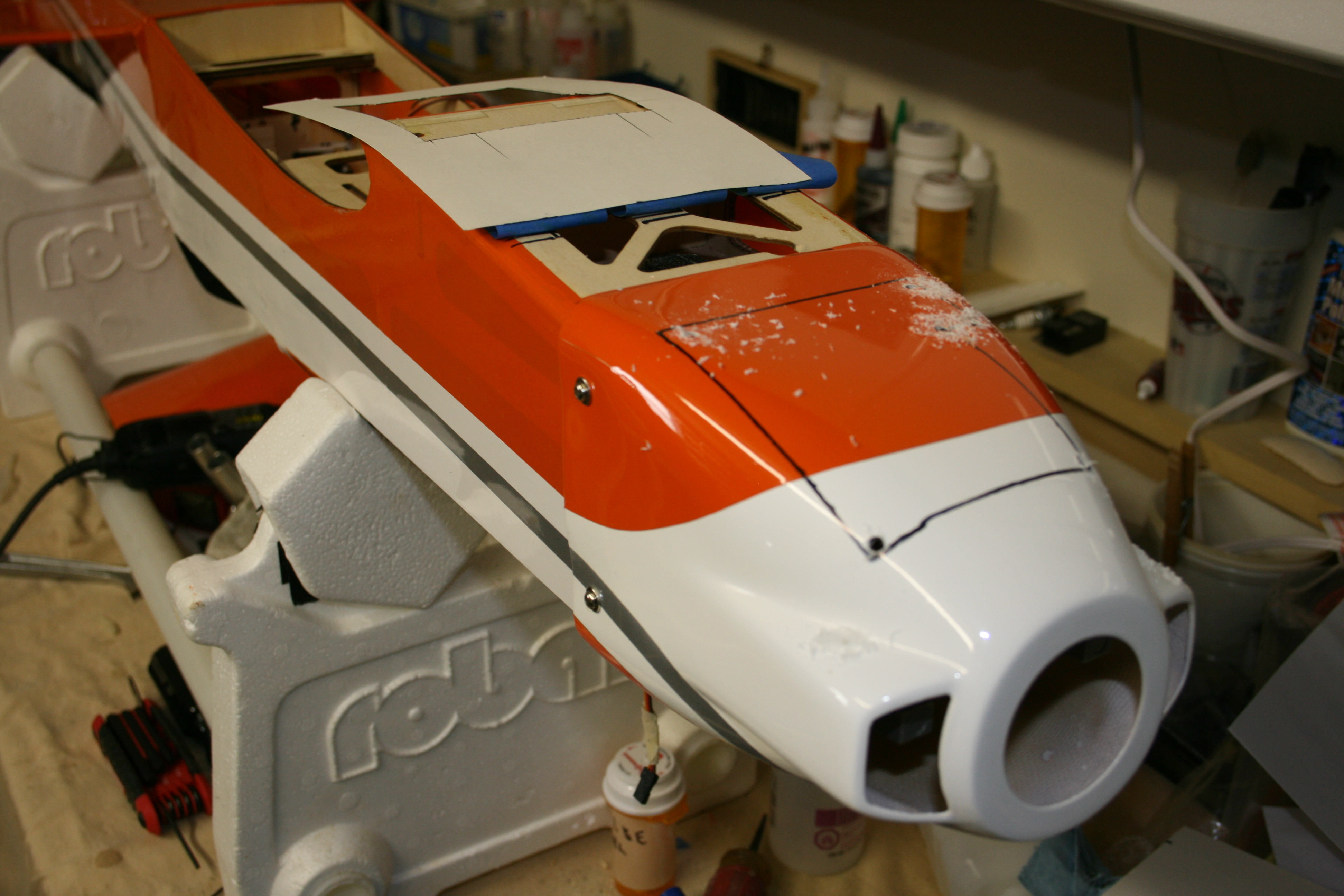
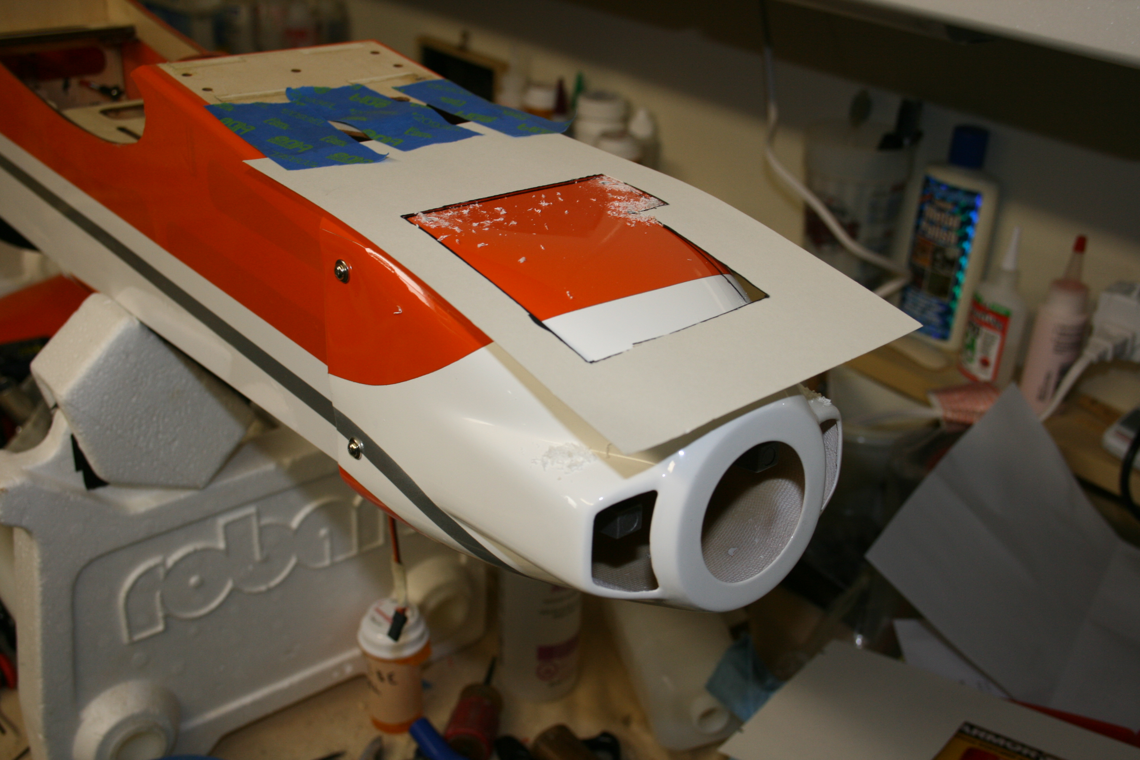
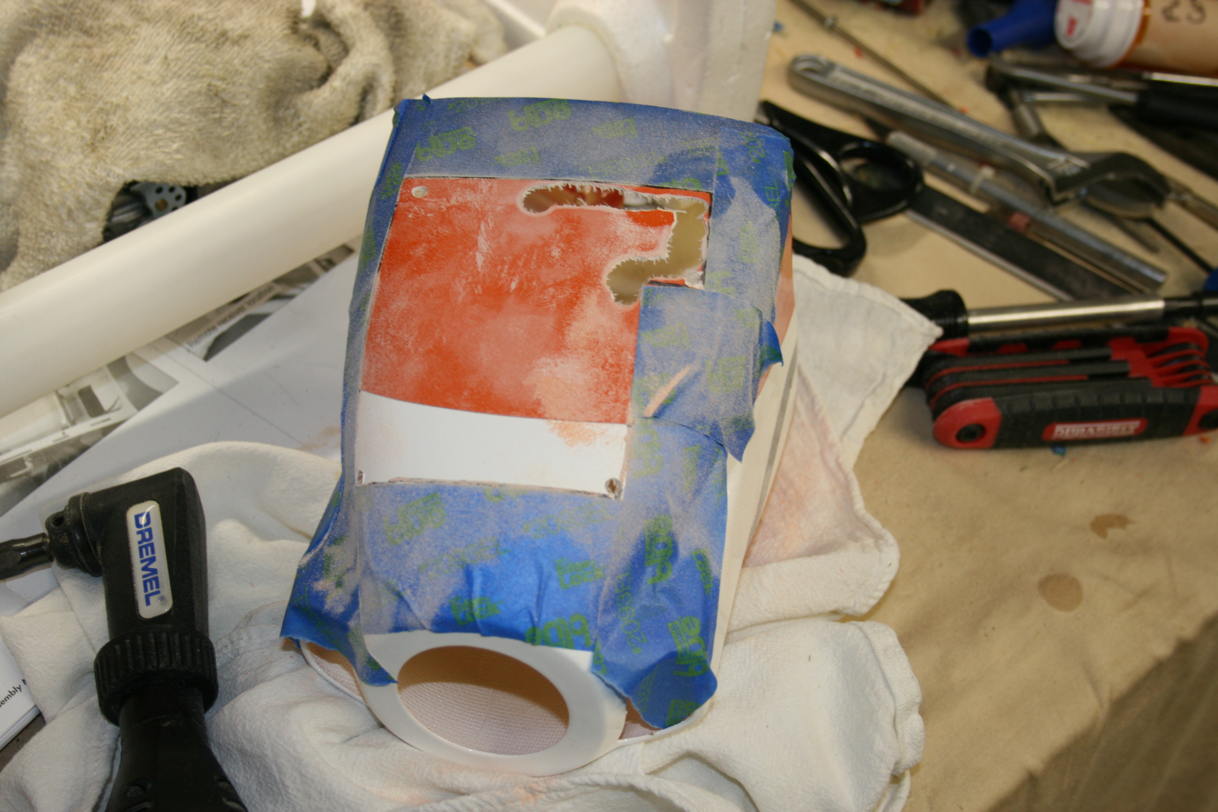
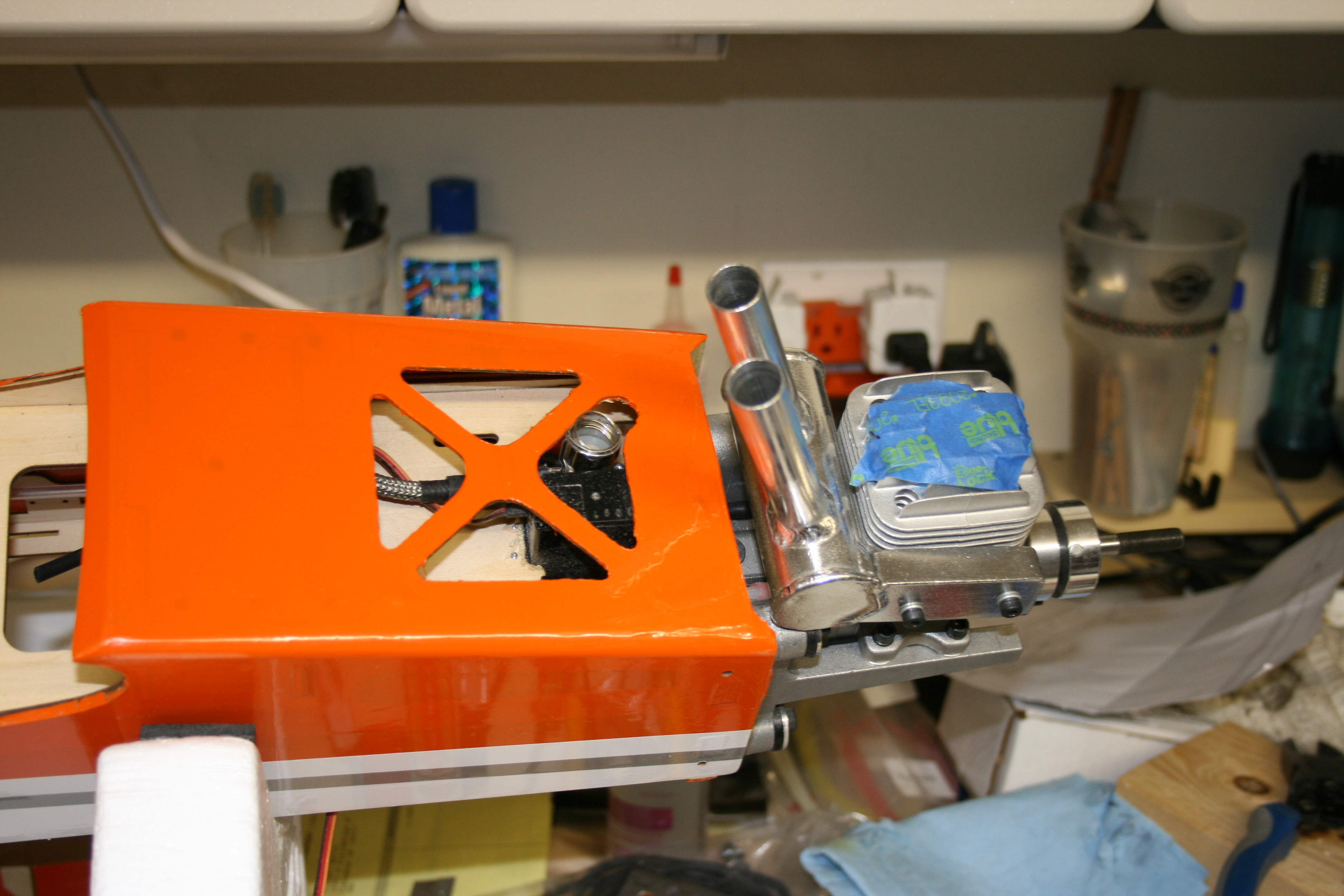
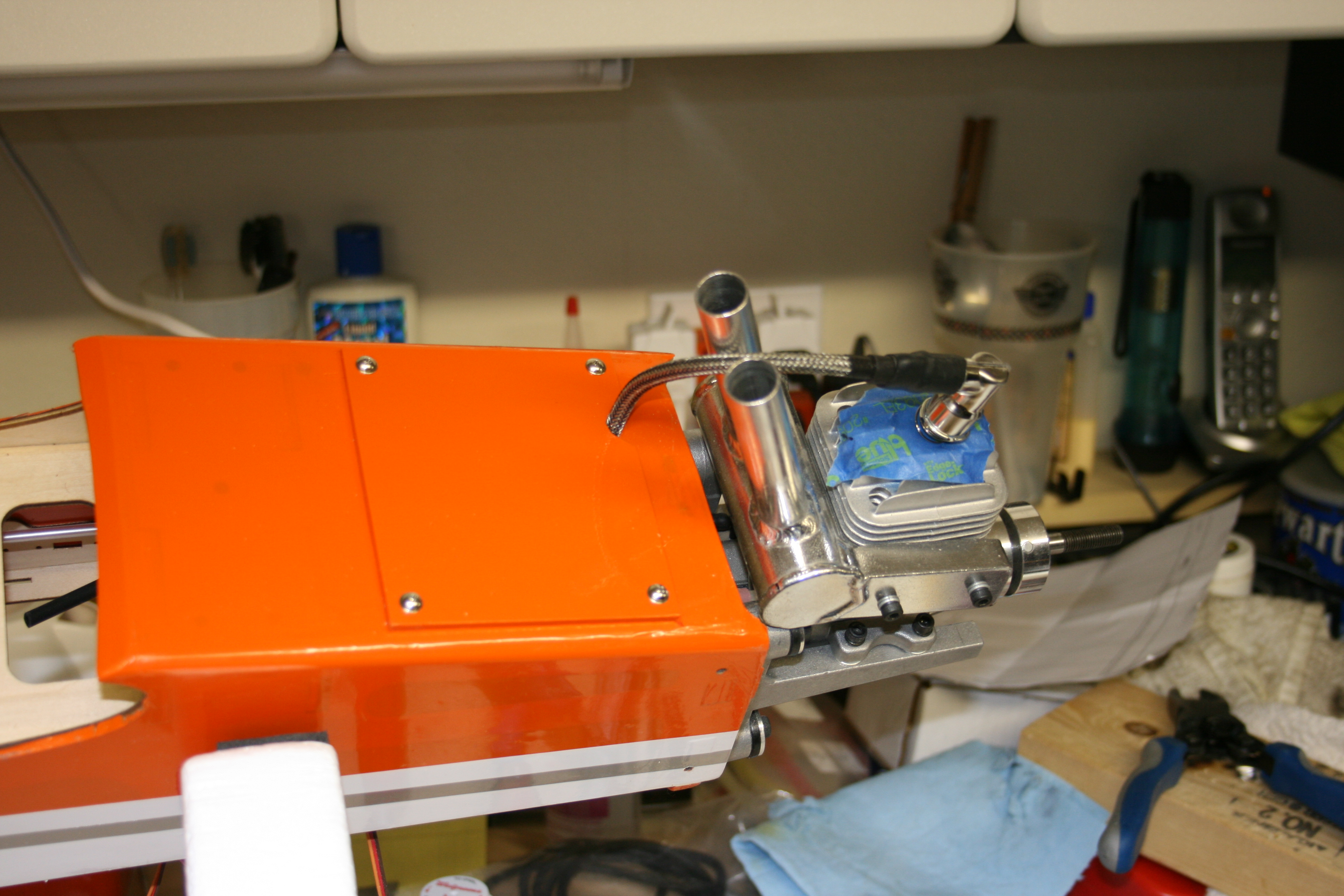
Ok next step is to test fit and install the cowling over the DLE 20 and the J-tec pitts muffler. After completing the template, I can see that enclosing it all in the cowl except for the cylinder head is a no go. Not that there is a lot of the engine exposed, but add the muffler, and it meant a large open area. That's ok, cooling is now a non issue and a lot of the cowling is left. First I sized and marked the template, then transferred the measurements to the cowl via a sharpie, and followed up with the ole Dremel. I have pictured my progress for those that might have questions on how it is done. When I searched for the steps on RCU, there was a lot of explanations, but not a lot of pics, so I thought I would supply them.
I have test fitted the cowl without the muffler due to the long pipes that block the rear of the cowl from moving into place. That's my next hurdle to overcome. I could cut through the back portion, open it up to move past the pipes, then add 2 mounting screws on the bottom, or try to figure out something else. Any ideas are certainly welcome. So far, I may just cut a thin line across the bottom rear of the cowl, open the back, slide the cowl past the pipes, then use 2 additional screws to hold it in place. The rest, including the space from cowl front to spinner are fine...could be a little closer to the spinner, but I have the DLE right up against the firewall already. Ok.on to the pics
.
Last edited by hookedonrc; 01-21-2014 at 07:41 AM.
01-21-2014 | 08:03 AM
#37
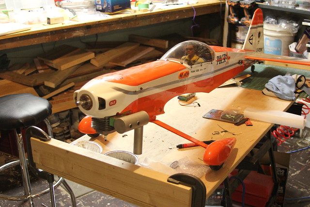
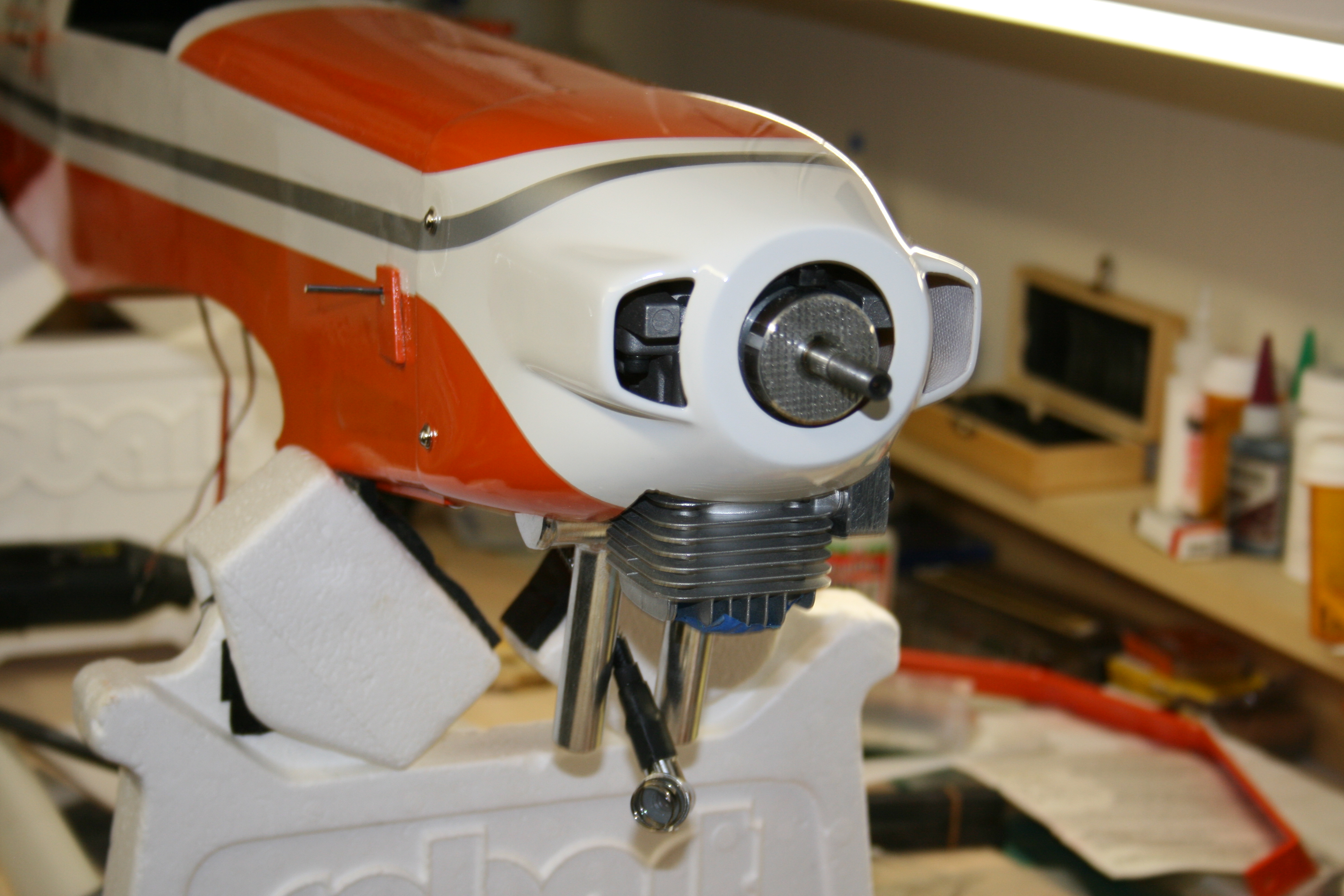
More work over the long weekend on the cowl. I took Macdona's advice from another thread and made a cut at the rear lower portion of the cowl. This allowed me to get it past the muffler pipes without having to make more adjustments in the size of the cutout I have made. Although it needs just a little more work, it fits and looks great on the plane. The cowl is touching the engine and muffler in a couple of places which I need to sand a little more to alleviate the problem. Here are a few pics of the install.
For those who have may noticed, I have done some more work on the choke lever that exits the right side of the fuse. I have tried several options, but just didn't like how it worked. I tried a L shape through the servo arm and a quick link, but the push rod was angled so much it grabbed. Any way, I will add pics and description to the thread when I get a chance. It works great now.


For those who have may noticed, I have done some more work on the choke lever that exits the right side of the fuse. I have tried several options, but just didn't like how it worked. I tried a L shape through the servo arm and a quick link, but the push rod was angled so much it grabbed. Any way, I will add pics and description to the thread when I get a chance. It works great now.
01-21-2014 | 09:59 AM
#38
Senior Member
Regarding the spinner I decided to go aluminum with mine too, but can't find a 2-1/2" three blade for love or money. I bought the 2-1/4" and 3" Tru-turns from the LHS to take home - the 3" is way too big and it looks like the 2-1/4" should fit so I'll give that a try.
Too little too late, hooked, but here are some pics from my cowl cutting.
Had to notch the fuse for the muffler.

Cut cowl

Engine in


It even works tolerably well with the RCGF 32 installed.
Too little too late, hooked, but here are some pics from my cowl cutting.
Had to notch the fuse for the muffler.
Cut cowl
Engine in
It even works tolerably well with the RCGF 32 installed.
01-21-2014 | 10:19 AM
#39
Thanks Grosbeak...on the spinner, it is a Tru-Turn but you can't find it on their website. I had to send them the 15X7X3 prop and they made me one on special order. I am not sure if once they get the measurements if they then make them as standard or not. I could not find a spinner of the right size either, and I didn't want to grind into one. On the muffler, it is from J-tec and is their small canister pitts wrap around...only issue I had was the clearing the motor mounts on the exhaust side of the cylinder head. I used my dremel and took off enough material on the engine mount for it to clear. It should not present a problem as most of the bottom of the mount is left.
oops forgot to add...the spinner is a 2 1/2.
oops forgot to add...the spinner is a 2 1/2.
Last edited by hookedonrc; 01-21-2014 at 10:21 AM.
01-21-2014 | 12:40 PM
#40
Senior Member
Thanks for the tips, hooked! I picked up a secondhand pair of 17 x 10 Biela carbon 3-blades for the Pulse with the RCGF32...

... they're in perfect shape and the two were far cheaper used than a single one new. And as it happens, the previous owner had shipped them down to Tru-Turn to have a custom spinner made. I don't have the spinner, but I'm hoping Tru-Turn still has the data... I've contacted them to find out.
... they're in perfect shape and the two were far cheaper used than a single one new. And as it happens, the previous owner had shipped them down to Tru-Turn to have a custom spinner made. I don't have the spinner, but I'm hoping Tru-Turn still has the data... I've contacted them to find out.
01-25-2014 | 01:48 PM
#41
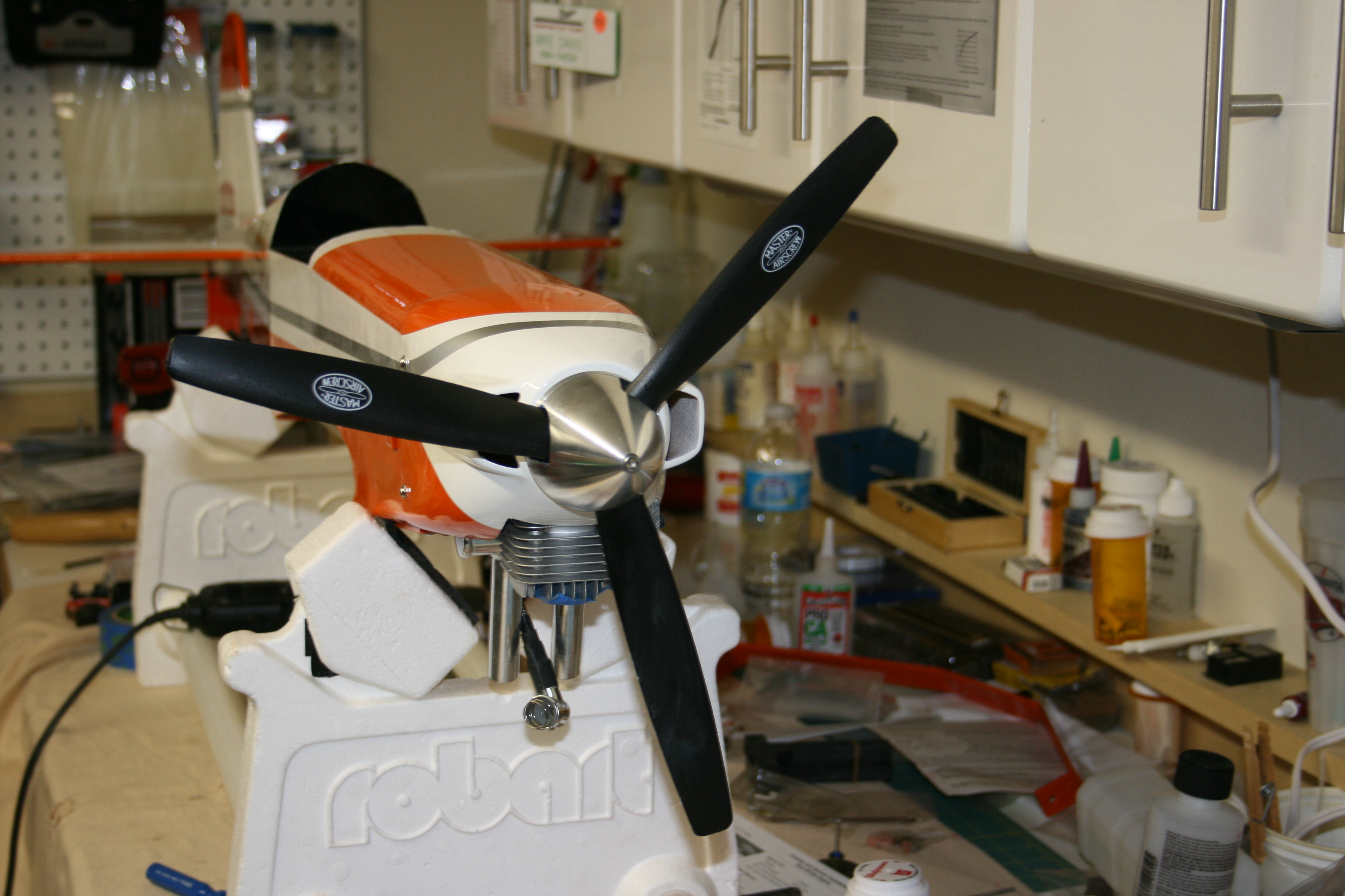
As many of you know, when you start to do modifications to an aircraft, it can lead to changes that you did not plan or that are necessary because of them. The Pulse 125 is no exception. Since I moved the throttle servo forward just behind the firewall, access to it needed to be improved. You can get to it from above, but with the DLE 20, there is a lot of stuff running from in front of the firewall to the electronic ignition, throttle, choke, fuel line. To provide additional space to get it at and to run the ignition, I did as others and put a hatch on the underside forward of the LG and just behind the cowling. Then as we do....and you know you do, I just couldn't resist putting on the cowl, spinner and prop to get a look at the front end when together. The prop spinner is a little more forward from the cowl that I would like, but the carb is right against the firewall and I don't want to take more away just to gain about 1/8". Here are the pics of the progress.


01-25-2014 | 08:38 PM
#42
Senior Member
Nice work!
I too added a hatch but it was strictly for the plug wire.

Thanks, by the way, for sending the MAS 15 x 7 3-blade to Tru-Turn for profiling... I ordered one for the Biela props pictured above. However, they ship to Canada at a flat rate ($30.00!) so I mitigated that by also ordering a 2-1/2" spinner profiled for the MAS prop - I use the same one on my DLE 20 and have had a plastic spinner up to now.
I too added a hatch but it was strictly for the plug wire.
Thanks, by the way, for sending the MAS 15 x 7 3-blade to Tru-Turn for profiling... I ordered one for the Biela props pictured above. However, they ship to Canada at a flat rate ($30.00!) so I mitigated that by also ordering a 2-1/2" spinner profiled for the MAS prop - I use the same one on my DLE 20 and have had a plastic spinner up to now.
01-26-2014 | 06:16 AM
#43
Thanks grosbeak, I considered doing the hatch like yours, and decided on the larger one. Since I already had the 4 spaces opened up and the servo and ignition wire are in that area, it made more sense.
02-15-2014 | 11:41 AM
#45
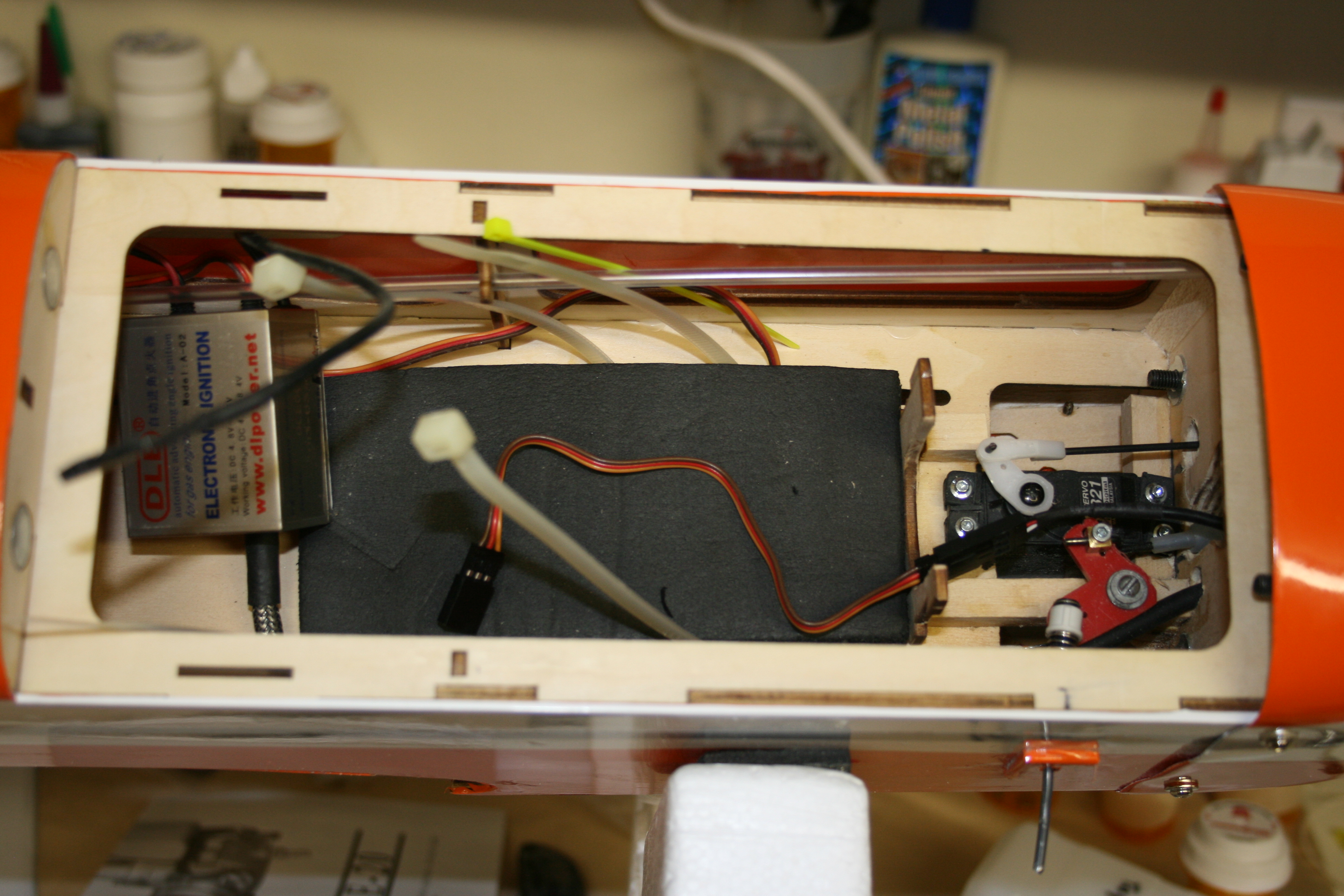
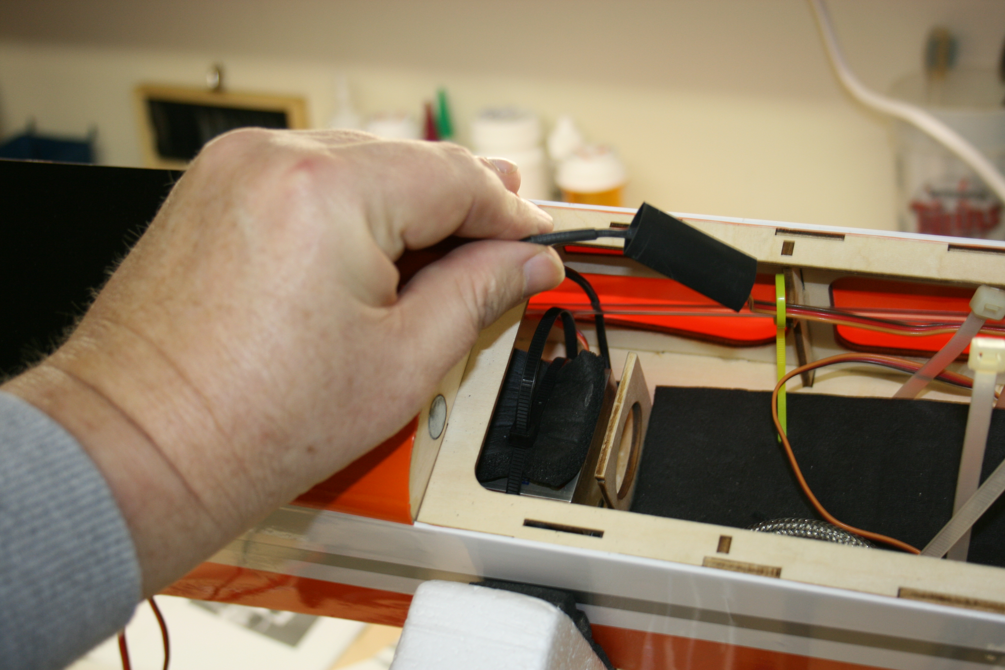
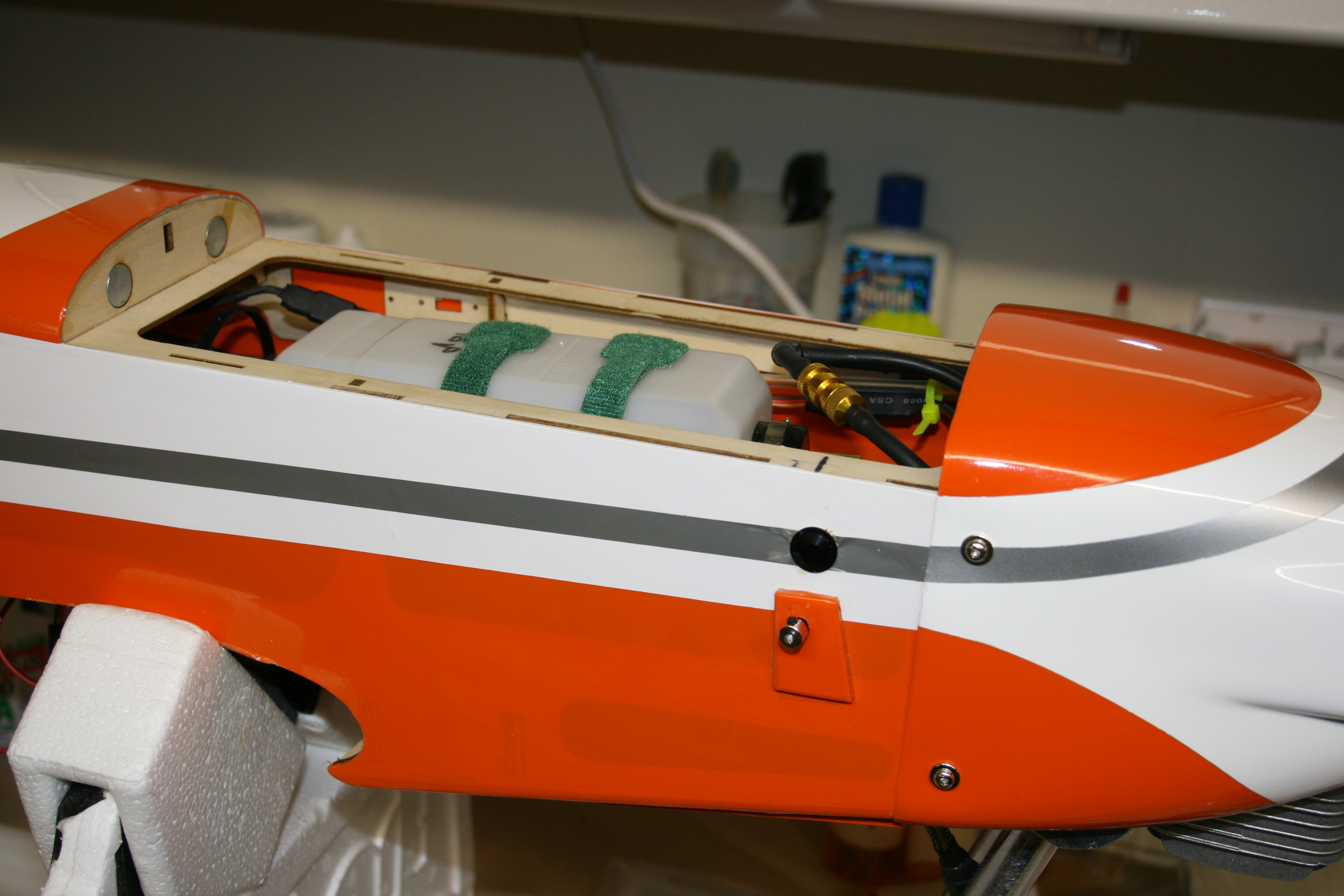
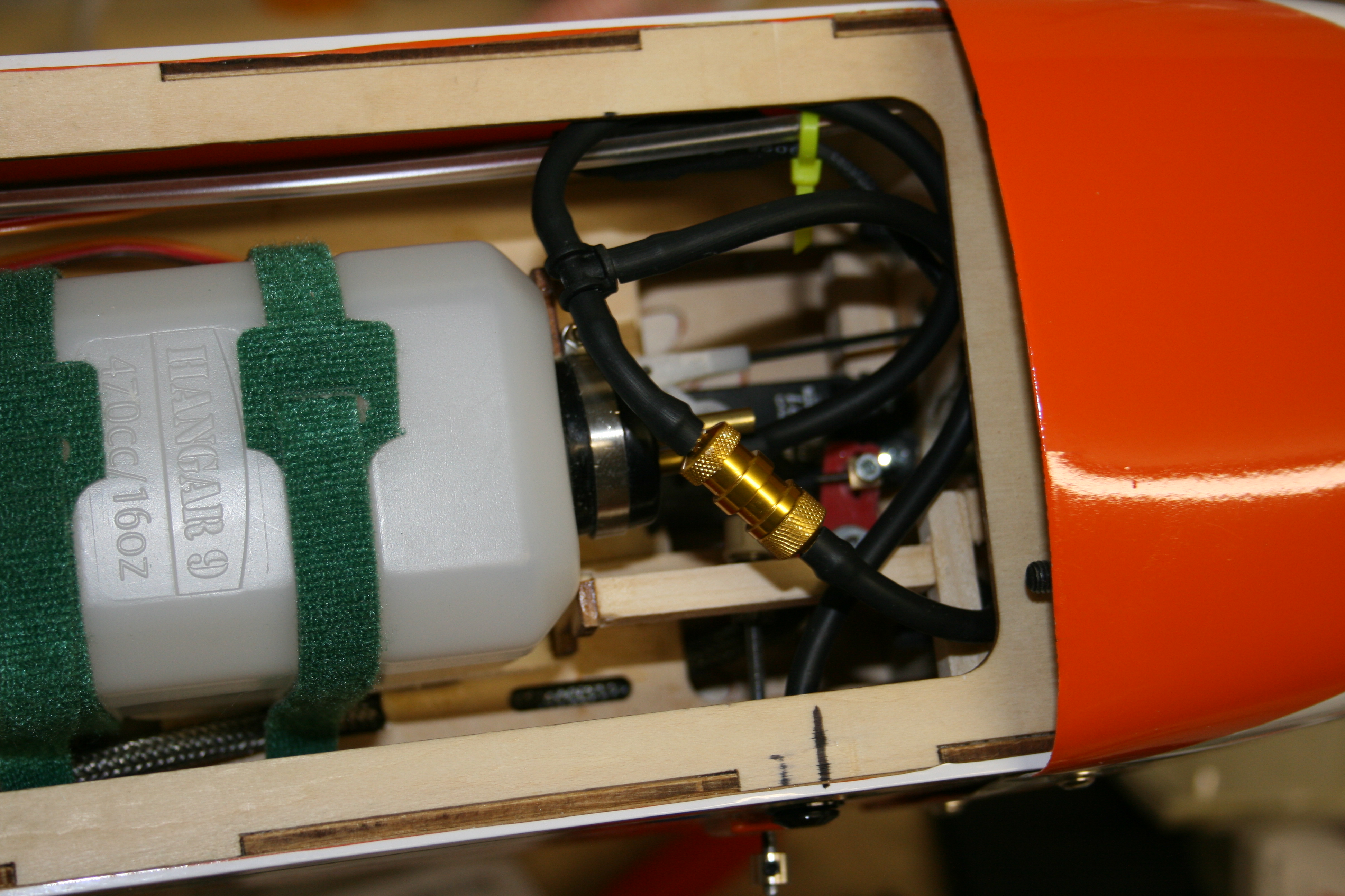
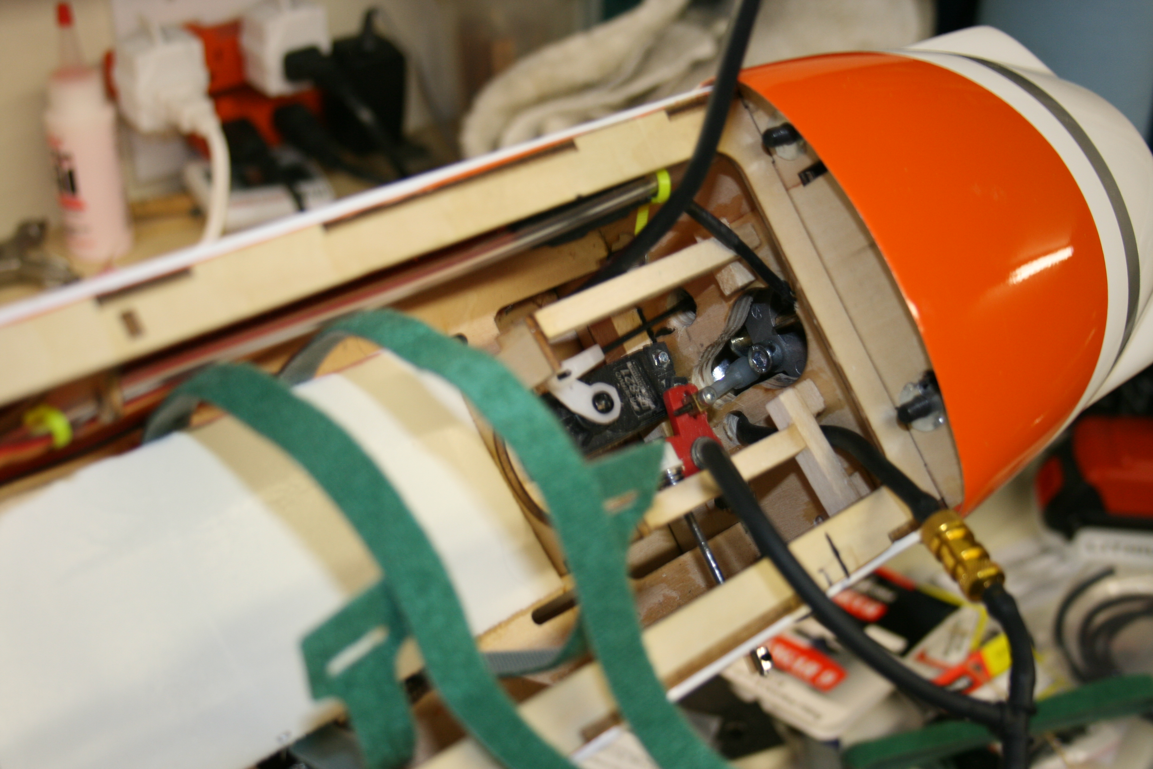
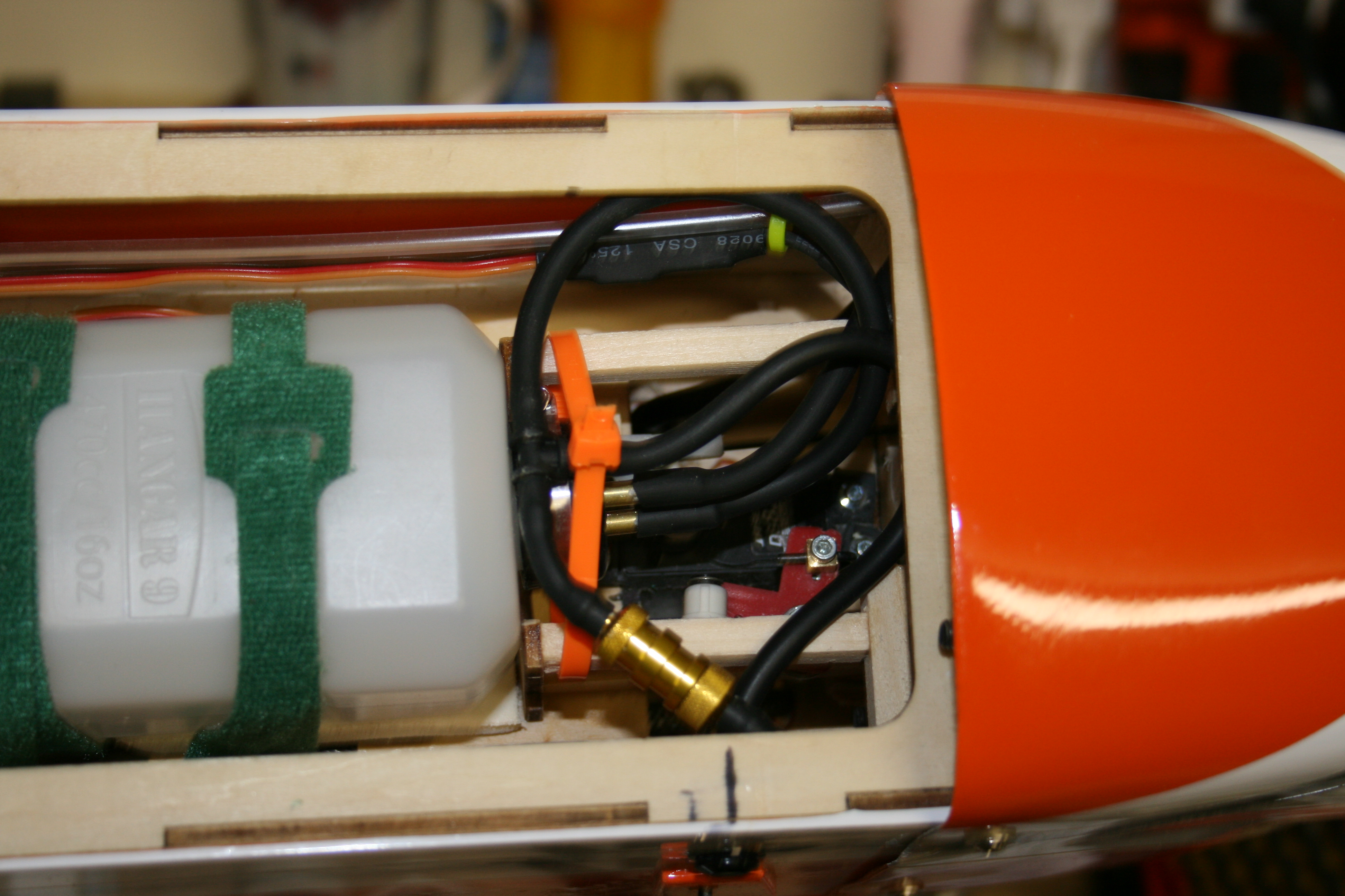
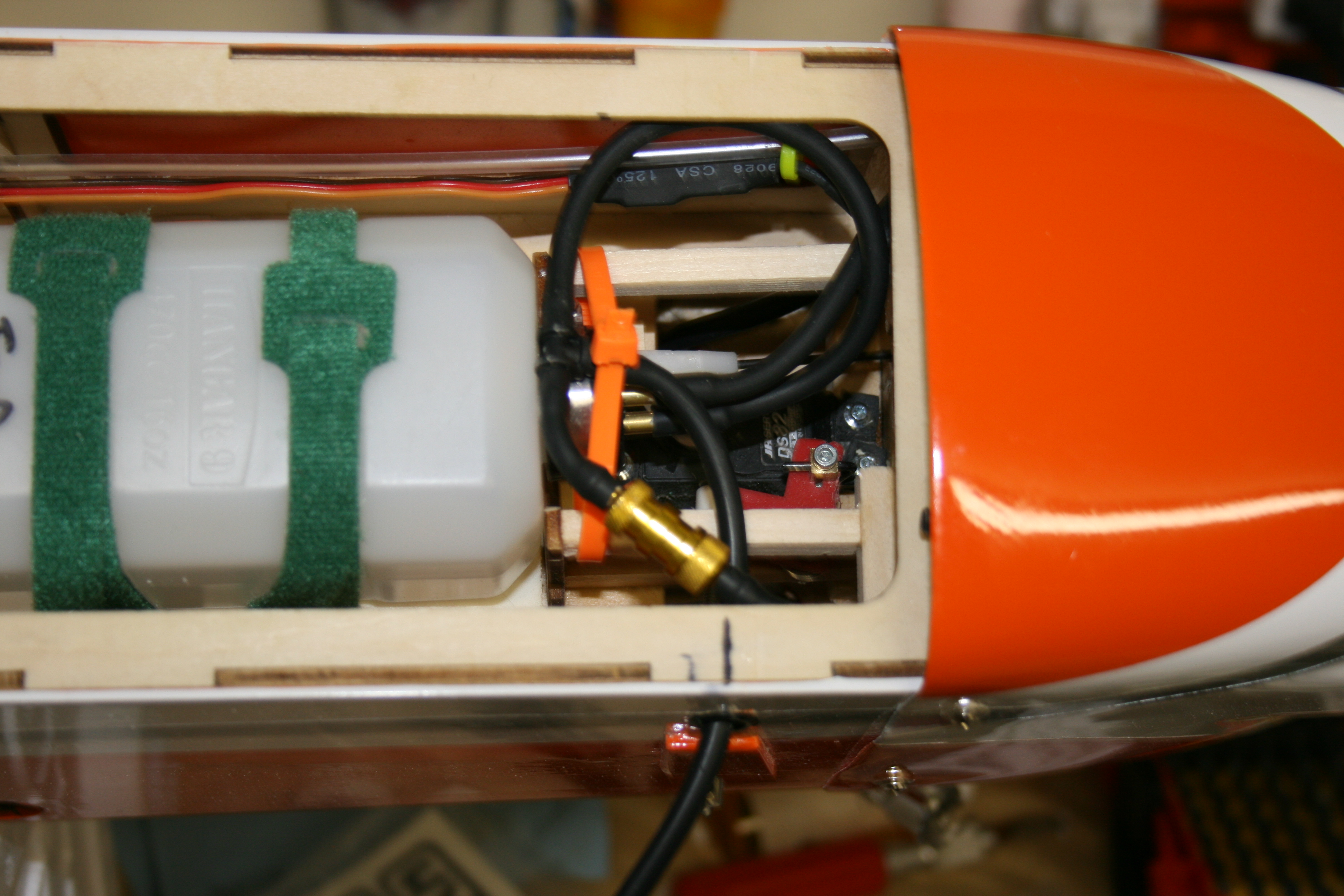
After suffering through the start of February (coldest on record) for Oklahoma anyway, I was able to get back in the shop and work on the 125. The ignition has been located behind the fuel tank and all necessary wiring put in place. Just a side note on this... If you ever get a 125 and are installing a DLE20, or probably any EI engine, it is possible that your wiring may be short. Mine was and after modifying a servo extension, it now is connected. No major modification except for the plug needing to be cleaned because of a tab on the outside. Once that was removed, all went together fine and rather than use the safety clips for the plugs, I used heat shrink tubing. Once the ignition was set, it was back to the fuel tank and lines. From the pictures, you can see that I have built a small block frame to hold the tubing away from the servo and choke lever. Final install was a fuel dot, with overflow vent in the fuse bottom which I have pictured. Installing the vent tubing really was easy since I created the access hatch. Then it was all back together and ain't she lookin' sweet? The fuel dot and choke lever are on the right side, easily accessable, and both work without any issue.
Next it is on to the receiver, battery, and optical kill switch. I am going to go with A123's (2200 MAH) from Hangtime as soon as I make sure what connections I want to order. I plan to put the optical kill switch light onto the instrument panel...cause...well where else should an instrument be?
Here are the pics. (Honestly trying to upload...process keeps locking up. Will try later.)
Last edited by hookedonrc; 02-15-2014 at 02:19 PM.
02-23-2014 | 12:07 PM
#47
Got my A123 (2500 MAH) battery via USPS yesterday from www.hangtimes.com from order to receipt of 3 days. What great service, and a great product as well. Anyway, I was at a stopping point until this came in, so I got a chance today to make more progress. I am also installing an Optical Kill Switch from Aerotech and with the battery here, I got started again. First step was to decide where to put the LED and it made sense to add it to the instrument panel. To avoid getting too close to the outside edge, I decided to use one of the existing instrument areas and began by drilling a very small hole. Wanted to make sure of location behind before I began to increase the size. It took some hand drilling, and filing in order to get it to fit properly and I finally got it right. Then it was time to run the connections and install the IBEC board so I made a small modification in the unused servo located at the front of the bay. Installed it using foam for cushioning and a zip tie because I am famous for having installed something to only have to remove it a day later, so I am ready.
It has become clear that space in the bay is at a premium with all the parts that need to be there. Servos, battery, kill switch, receiver, and wiring, so i am pausing to design and install a 2 level electronics area. The battery will go right behind the kill switch with the receiver sitting on a shelf just above. I will make it removable should I need to get at the servos and or battery....oh yes I will, you know I will. So here are the pics for today...time to watch Daytona...although they are in a rain delay.


It has become clear that space in the bay is at a premium with all the parts that need to be there. Servos, battery, kill switch, receiver, and wiring, so i am pausing to design and install a 2 level electronics area. The battery will go right behind the kill switch with the receiver sitting on a shelf just above. I will make it removable should I need to get at the servos and or battery....oh yes I will, you know I will.
So here are the pics for today...time to watch Daytona...although they are in a rain delay. Last edited by hookedonrc; 02-24-2014 at 07:13 AM.
02-23-2014 | 03:34 PM
#48
I decided that the delay in the race was too long, so went back to work. After deciding that a 2 shelf area is needed for the battery and receiver area, I went to work constructing one. I put it over the kill switch only to discover the battery is too thick and would keep the wing from fitting properly. So all I did was extend the bracing rearward until the battery was clear. By then, the ply piece was too small to cover the whole area, but that isn't a big deal as I can make a 2 piece shelf. I have added the most recent pics and will continue later.


