


SIG Rascal 110 ARF Build Thread

 08-05-2023, 05:20 AM
#77

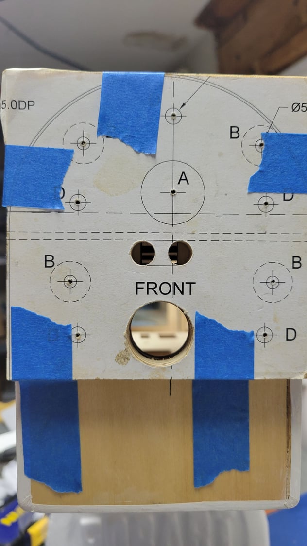
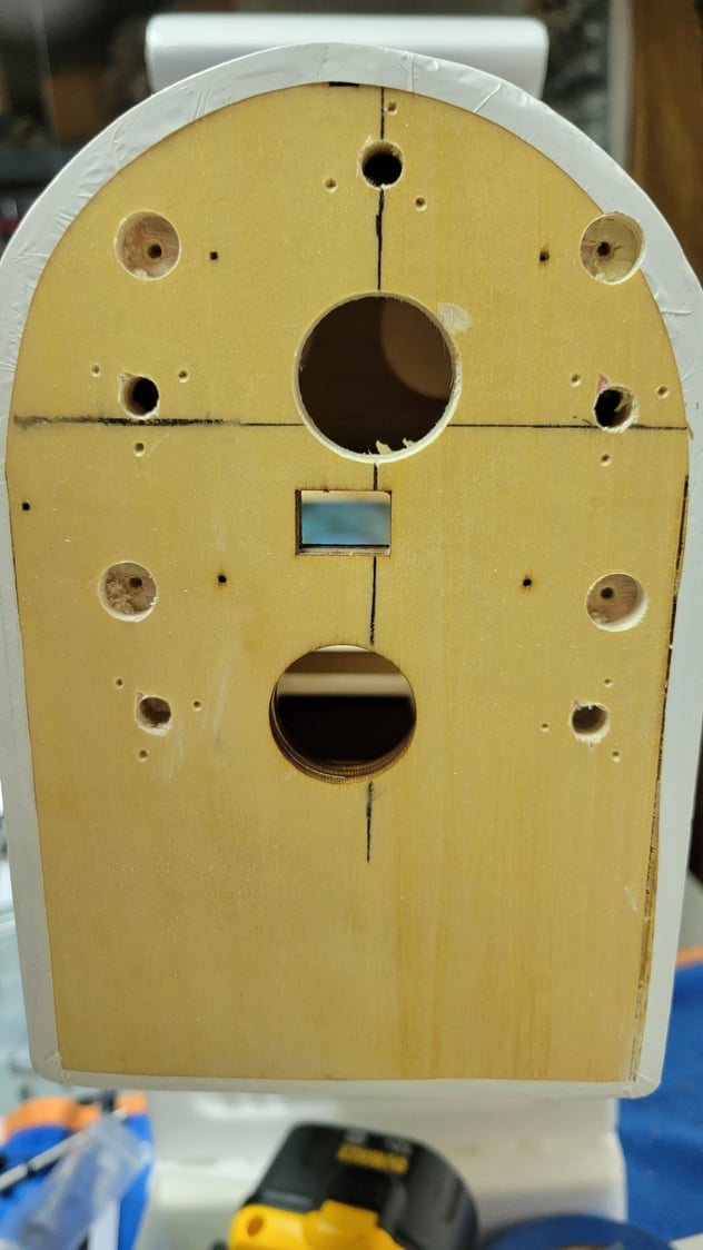
Tape the plate securely to the front of the fuselage. Make sure you align the thrust line marks both vertical and horizontal.
Drilling the firewall: Because you can’t realistically put this in a drill press, I like to use the Harry Higley drill guides to keep the holes square when using a hand drill.
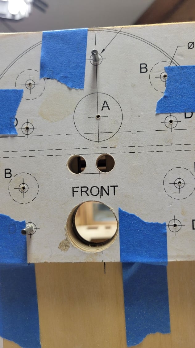
What I did next may seem a bit more complicated than it needs to be, but I’m a stickler for accuracy. I drilled (1) 1/8” hole through all at the top location “D”. I then pressed a 1/8” dowel pin in this location.
Check alignment again and drill another 1/8” hole at either of the bottom 2 “D” locations. Press in a 1/8” dowel pin here. The pins will prevent any shifting while drilling the remaining holes.
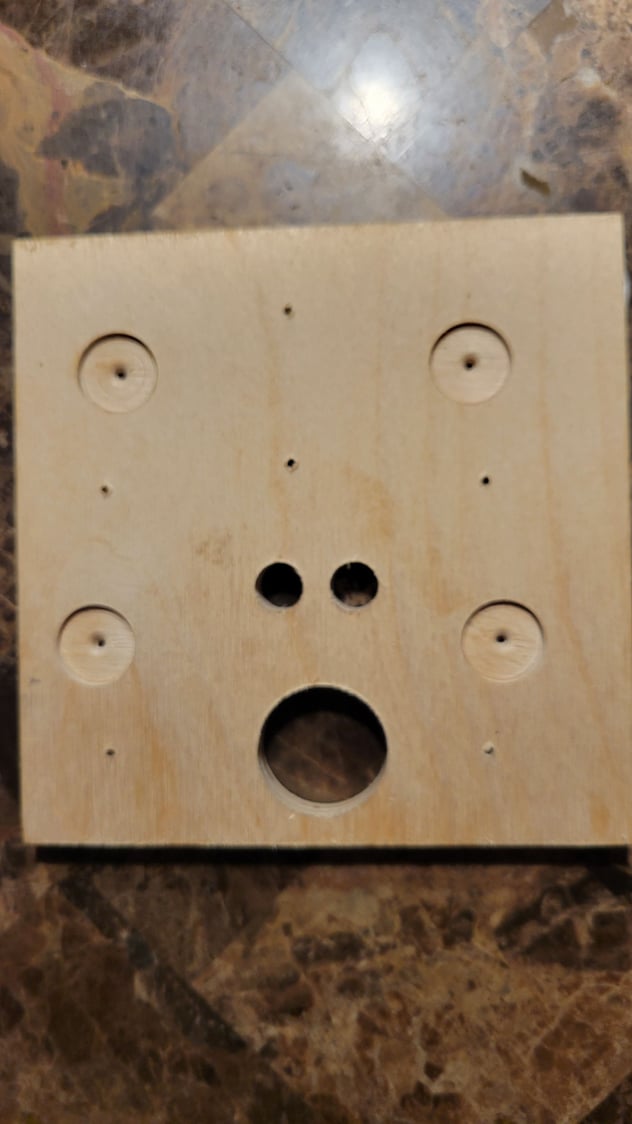
At this point, assuming all is still in alignment relative to the thrust lines, drill the remaining holes with a 3/32” bit.
Remove the engine plate and pins and verify that you have all the required holes before proceeding further.
Drilling the firewall: Because you can’t realistically put this in a drill press, I like to use the Harry Higley drill guides to keep the holes square when using a hand drill.
What I did next may seem a bit more complicated than it needs to be, but I’m a stickler for accuracy. I drilled (1) 1/8” hole through all at the top location “D”. I then pressed a 1/8” dowel pin in this location.
Check alignment again and drill another 1/8” hole at either of the bottom 2 “D” locations. Press in a 1/8” dowel pin here. The pins will prevent any shifting while drilling the remaining holes.
At this point, assuming all is still in alignment relative to the thrust lines, drill the remaining holes with a 3/32” bit.
Remove the engine plate and pins and verify that you have all the required holes before proceeding further.
 08-05-2023, 05:28 AM
#79
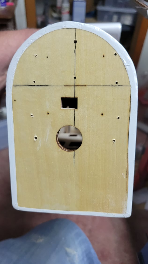
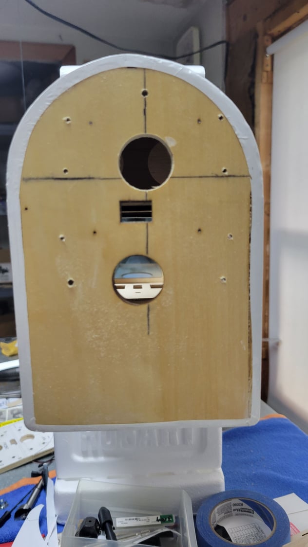
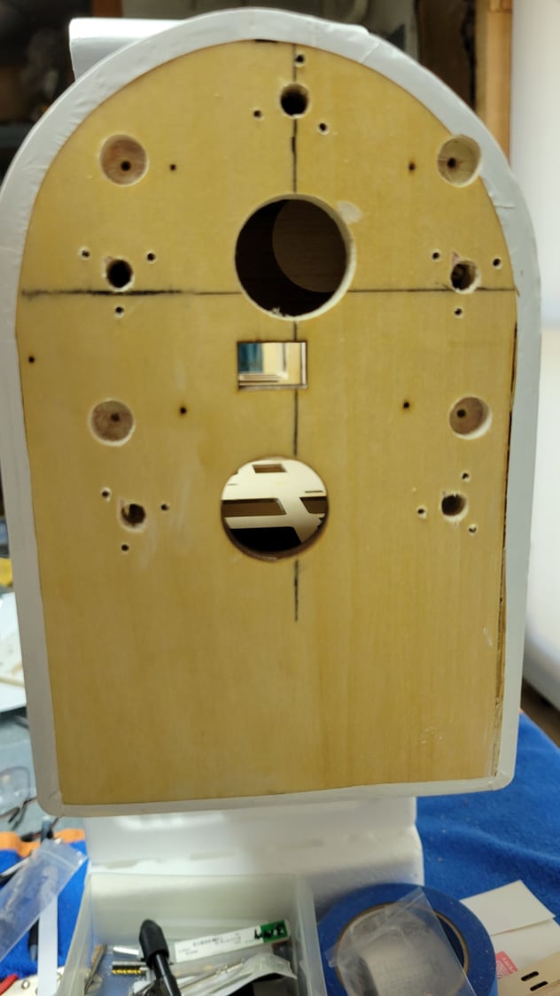
Using a 1” Forstner bit, drill through the firewall at the upper location of hole “A”. This will give some access to the area in the upper section behind the firewall. A note of caution: There is a structural member just above the rectangle cutout in firewall. The center of the hole should be about ľ” above the top of the rectangle cutout. More to come........
08-08-2023, 05:05 AM
#80
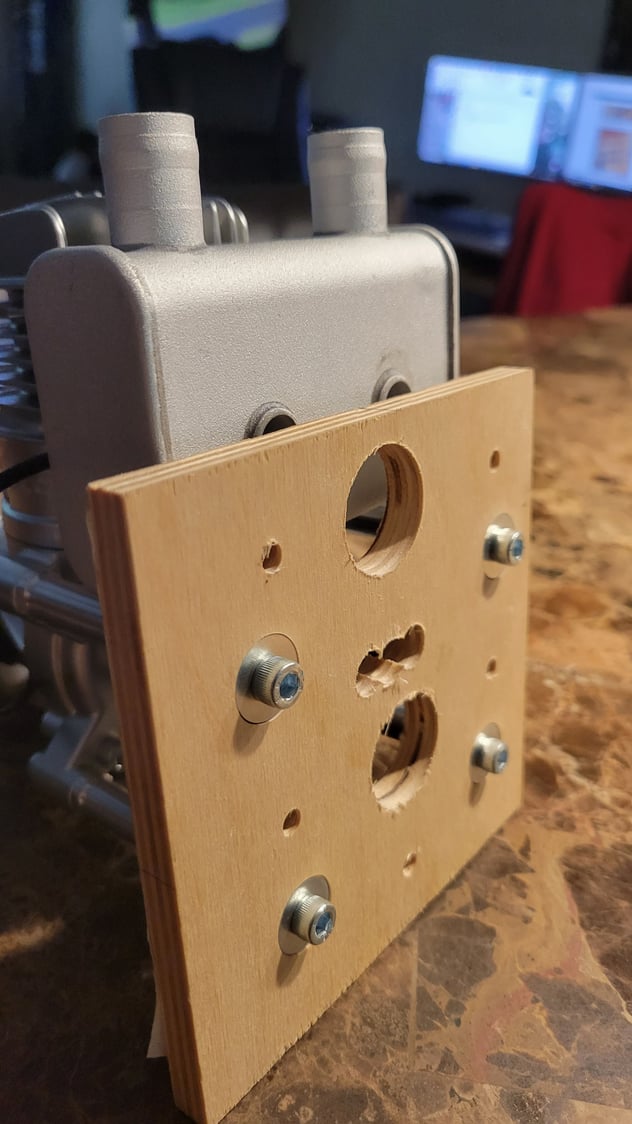
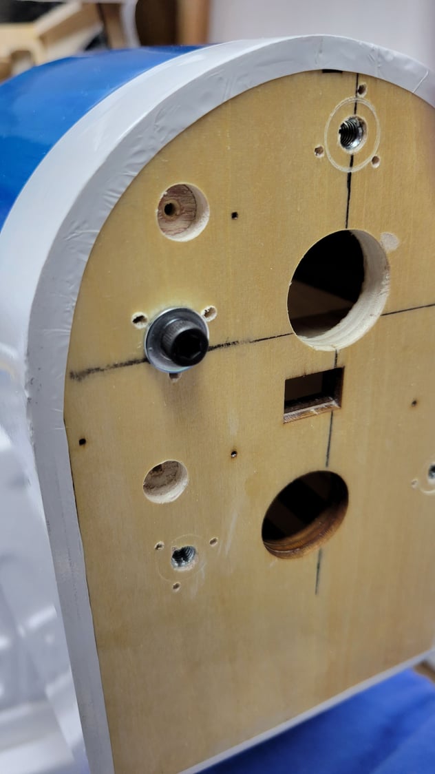
On the firewall, counterbore the (4) holes at “B” with a 3/8” Forstner bit to a depth of about .25. This will give clearance for the bolt heads from the standoffs.
Drill out the (5) holes “D” to Ľ” diameter on the firewall.
It’s been my experience that tee nuts don’t like to pull down flush in plywood unless you can pound them with a hammer. Since that is not possible here what I do is place the tee nut in the hole and tap it to mark the location of the barbs. Keep the drill square to the firewall and drill through at all locations. I used a 5/64” drill, but 3/32” would work just fine.
08-09-2023, 04:14 AM
#81
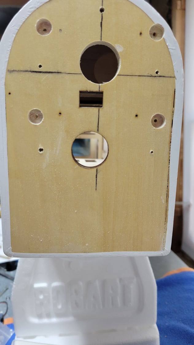
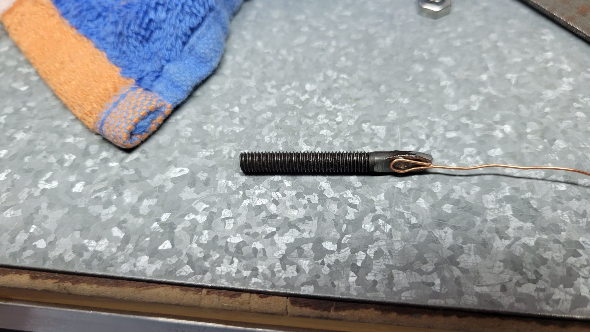
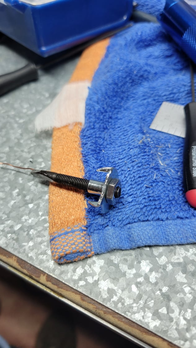
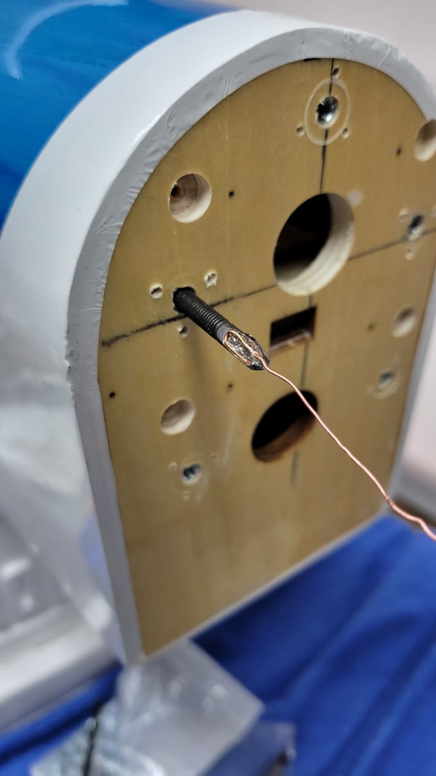
Installing the tee nuts is a bit tricky, but I made a tool out of a 10-32 bolt and glued a length of copper wire to it to thread it through from the backside of the firewall. I noted that the lower right location was close to some triangle stock on the backside, so I trimmed the tee nut for that location. The jam nut is put on just hand tight to hold the bolt in position such the flat side of the modified bolt aligns withe one of the barbs. That way you can know where the barbs are relative to the holes when it's behind the firewall. The idea is to form a "U" in the end of the copper wire to loop it in and out the desired hole. Apply some 30-minute epoxy to the flange and barrel of the tee nut and draw it into position with the wire. You might want to practice this without the epoxy first.
08-09-2023, 04:18 AM
#82
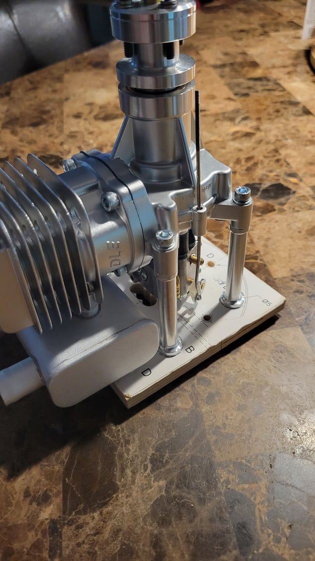
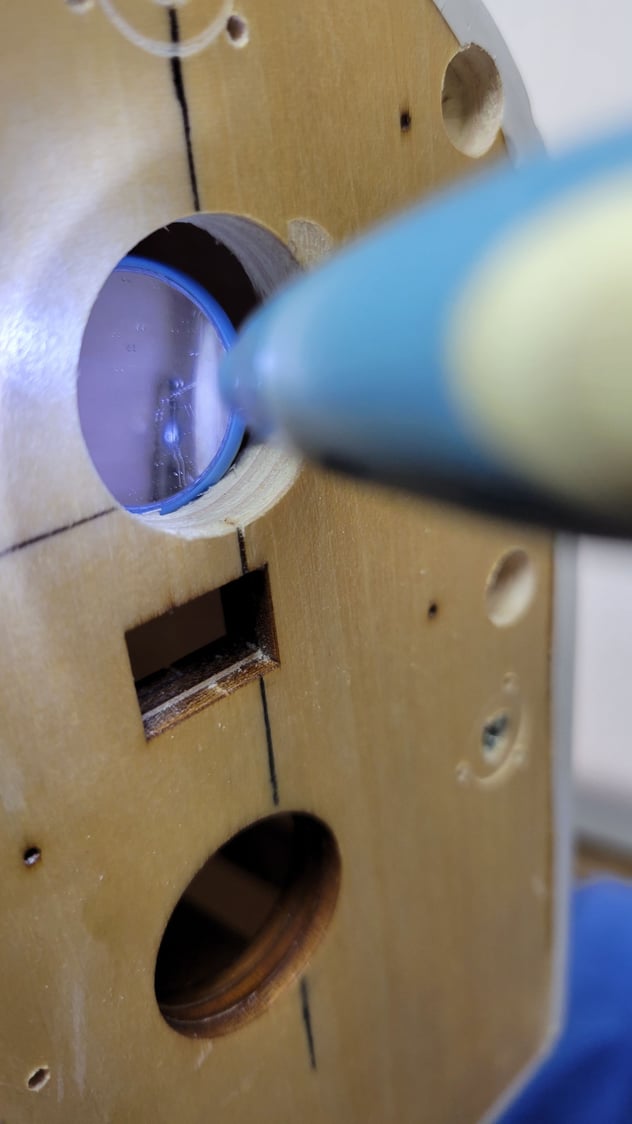
Carefully screw in the pilot bolt about a turn or 2 until it feels loose. with your finger on the nut, unscrew the pilot bolt and set aside. Run a 10-32 bolt with a large washer into the tee nut and tighten until it pulls up tight to the back of the firewall.
Check with an inspection mirror to make sure the tee nut is pulled in fully. Final check of the fit and you’re done except for working out the throttle pushrod location. I will give the plate a couple coats of polyurethane. Note the use of button head screws. I found that there was a slight interference between the bottom 2 bolts and the muffler. The button head screws cures that.
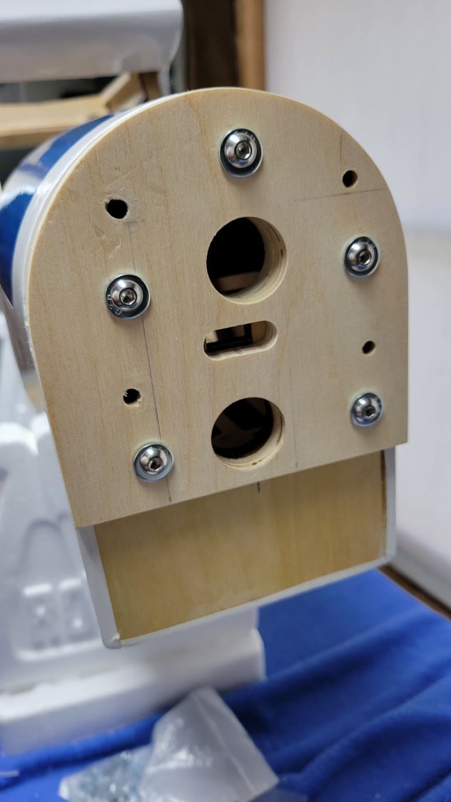
Check with an inspection mirror to make sure the tee nut is pulled in fully. Final check of the fit and you’re done except for working out the throttle pushrod location. I will give the plate a couple coats of polyurethane. Note the use of button head screws. I found that there was a slight interference between the bottom 2 bolts and the muffler. The button head screws cures that.
10-22-2023, 08:24 AM
#83
I recently was putting the finishing touches on the

Sig Rascal 110. I applied the decals using the Windex method. All went well until a couple of hours later and I found that there was a "blooming/blushing" look around the middle (see pic). Any ideas on how to fix this? I've never had this happen before.
Sig Rascal 110. I applied the decals using the Windex method. All went well until a couple of hours later and I found that there was a "blooming/blushing" look around the middle (see pic). Any ideas on how to fix this? I've never had this happen before.
