


SIG Rascal 110 ARF Build Thread
 06-19-2015, 09:26 AM
#1
Senior Member
Thread Starter

I bought a SIG Rascal 110 ARF last summer as soon as they came in. About a week ago, I bought the servos & various things to get her together. Everything in the picture below except for the "woodpecker", 15 X 5 XOAR propellers & black nylon 1/4-20 wing bolts is for the Rascal.
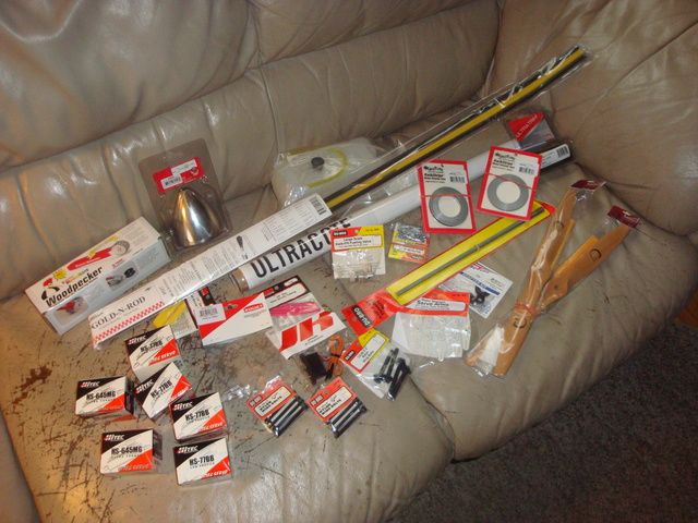
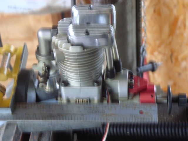
The goal it to build it as light as reasonably possible & power it W/a hopped up high compression Saito FA-180 burning glow fuel W/CDI. The engine should be capable of 8400+ RPM (static) W/an 18X8 prop so if I can keep the weight near 12#, it should have impressive vertical performance.
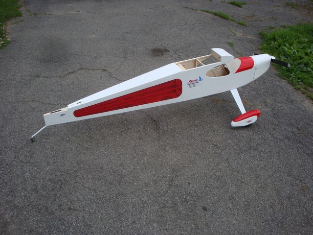
The 1st thing I did was pull the Ultracote from the bottom of the fuselage. I want to make a hatch just behind the firewall to access the CDI module. I may or may not install a 2nd hatch aft of the CG if I need to shift weight W/battery packs. I'm hoping to avoid that.
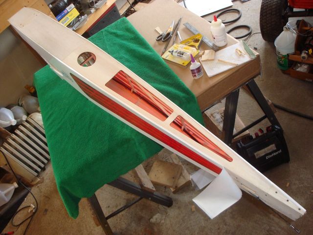
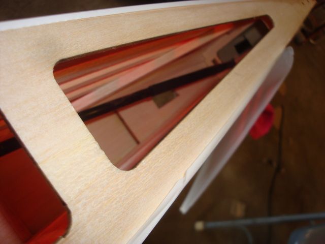
Another change I am making is to mount the elevator servo under the wing. I am using a Hitec HS-645MG for the elevator & rudder & wanted to avoid the weight in the tail.
I peeled back the Ultracote on the starboard side under the horizontal stabilizer. I then filed an oblong slot at the top of the factory servo mount hole to allow the installation of the outer tube for the Sullivan high stress nylon pushrod W/4-40 ends.
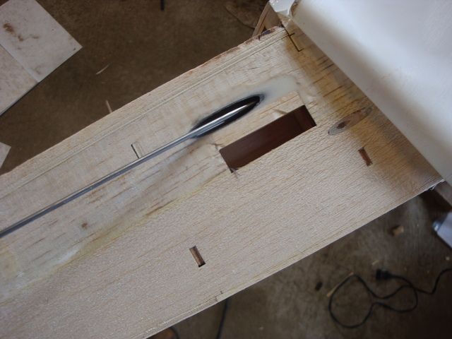
After gluing the tube in the hole W/CA & adding some balsa fill under it, I mixed up some micro-balloons & epoxy to fill around & anchor the tube.
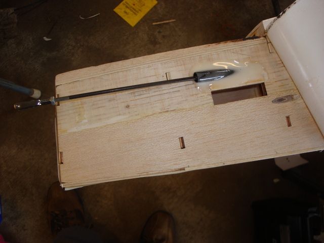
I made anchor blocks out of 1/4" balsa & glued them to locate the tube behind one of the fuselage stringers for aesthetic purposes.
By routing the tube to the opposite side of the fuselage, there is a very gentle curvature to the tube & the pushrod operates freely.
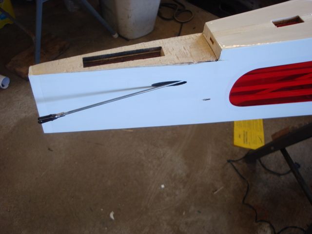
After letting the epoxy/micro-balloons set up overnight, I sanded the tube flush W/the fuselage.
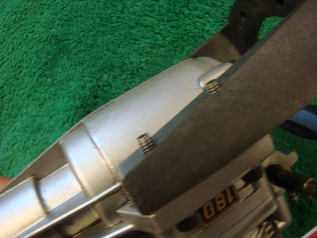
Here is the final result after re-attaching the Ultracote.
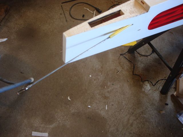
The large diameter semi-ridged nylon portion of the pushrod seen here is hidden a few inches inside the tube when attached to the elevator.
Next step is to mount the engine so I can plan out the hatch & location of the ignition module. I may also have to make modifications to the firewall to allow the muffler to point down & centered.
The goal it to build it as light as reasonably possible & power it W/a hopped up high compression Saito FA-180 burning glow fuel W/CDI. The engine should be capable of 8400+ RPM (static) W/an 18X8 prop so if I can keep the weight near 12#, it should have impressive vertical performance.
The 1st thing I did was pull the Ultracote from the bottom of the fuselage. I want to make a hatch just behind the firewall to access the CDI module. I may or may not install a 2nd hatch aft of the CG if I need to shift weight W/battery packs. I'm hoping to avoid that.
Another change I am making is to mount the elevator servo under the wing. I am using a Hitec HS-645MG for the elevator & rudder & wanted to avoid the weight in the tail.
I peeled back the Ultracote on the starboard side under the horizontal stabilizer. I then filed an oblong slot at the top of the factory servo mount hole to allow the installation of the outer tube for the Sullivan high stress nylon pushrod W/4-40 ends.
After gluing the tube in the hole W/CA & adding some balsa fill under it, I mixed up some micro-balloons & epoxy to fill around & anchor the tube.
I made anchor blocks out of 1/4" balsa & glued them to locate the tube behind one of the fuselage stringers for aesthetic purposes.
By routing the tube to the opposite side of the fuselage, there is a very gentle curvature to the tube & the pushrod operates freely.
After letting the epoxy/micro-balloons set up overnight, I sanded the tube flush W/the fuselage.
Here is the final result after re-attaching the Ultracote.
The large diameter semi-ridged nylon portion of the pushrod seen here is hidden a few inches inside the tube when attached to the elevator.
Next step is to mount the engine so I can plan out the hatch & location of the ignition module. I may also have to make modifications to the firewall to allow the muffler to point down & centered.
Last edited by SrTelemaster150; 06-19-2015 at 03:04 PM.


 06-19-2015, 01:14 PM
#5

Good looking work there. Bones are nicely laid out too.
Hey y'all, got a newbie question here - how do you detach something like ultracote in the first place without damaging it?
Hey y'all, got a newbie question here - how do you detach something like ultracote in the first place without damaging it?
06-19-2015, 02:58 PM
#6
Senior Member
Thread Starter
I left out the picture of me soldering the clevis to the blank end of the 4-40 pushrod.
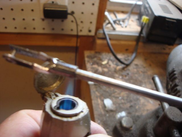
I like to solder one end & use a screw clevis on the other. That eliminates any possibility of the clevis backing off so jam nuts can be eliminated. The threaded rod will not back out of the nylon push tube. It is just like a nylock nut in that respect. The "metric" screw clevis from the kit was just the right size to slip over the blank end of the 4-/40 rod
I picked up some 3/16" X 3/8" basswood from the LHS to make a tray for the elevator servo & I'll use some 1/32" birch ply to make a mounting surface for they Rx. I had to go to the HDWE store to get some 10-32 blind nuts for the main gear. I am using 10-32 nylon wing bolts in lieu of the steel bolts to attach the main gear in the hopes that a hard noise down landing won't result in pulling the bottom of the fuselage apart.
I bought that little butane torch @ the local ACE Hardware store a while back. It's awesome for soldering landing gear, "Y" pushrods & clevises.
One fill is enough to do quite a bit of soldering. It fills W/a standard butane lighter fuel can. If I remember correctly, it was less than $5.
Last edited by SrTelemaster150; 06-19-2015 at 06:55 PM.
06-19-2015, 03:09 PM
#7
Senior Member
Thread Starter
As an ARF comes shipped, the Ultracote/Monokote isn't really ironed down tightly. That's why the instructions tell you to go over it W/an iron. If you are VERY careful, paying particular attention to inside corners, you can GENTLY pull the film up. It will reseal W/an iron.
 06-19-2015, 06:27 PM
#9

Here is how it feels to be on board..
https://www.youtube.com/watch?v=fPdTltljjyM https://www.youtube.com/watch?v=KRhXtg1xkxU https://www.youtube.com/watch?v=T5_OPlpSSO4
https://www.youtube.com/watch?v=fPdTltljjyM https://www.youtube.com/watch?v=KRhXtg1xkxU https://www.youtube.com/watch?v=T5_OPlpSSO4
Last edited by foodstick; 06-19-2015 at 06:31 PM.
06-19-2015, 08:40 PM
#10
GREAT videos, all 3!!!!!!!!!
Nice plane!!
Nice plane!!
06-20-2015, 04:48 AM
#11
Senior Member
Thread Starter
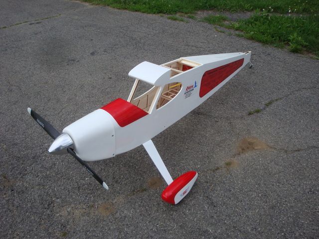
This isn't my plane obviously, but this might give someone that isn't familiar W/this bird some idea of the size.
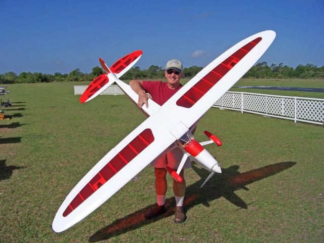
I'm going to nickname mine "Ultracote Overcast".
I'm going to nickname mine "Ultracote Overcast".
06-20-2015, 09:07 AM
#12
Senior Member
Thread Starter
I like the Dave Brown glass filled nylon mounts. I used one for quite some time on my 89" WS Dynaflite PT-19 W/an FA-150. They are light, exceedingly strong for the application & they tend to dampen the transmission of vibration to the airframe. I will be going to greater lengths in that last respect by using rubber "well nuts" in lieu of "T" nuts in the firewall.
More on that in the next post.
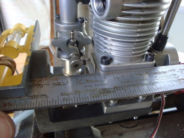
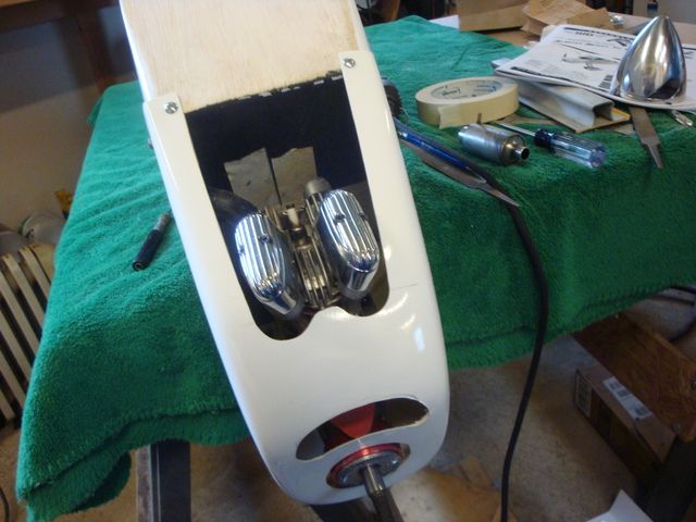
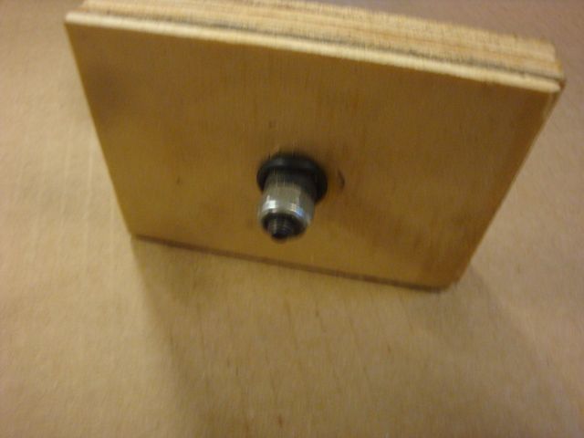
I started out by clamping the mount in the drill press vise to determine the 6" recommended distance form the firewall to the prop hub. (sorry for the out of focus shot, I didn't have the camera set for close-up)
After establishing the distance, I checked to assure that the engine was square to the base of the mount.
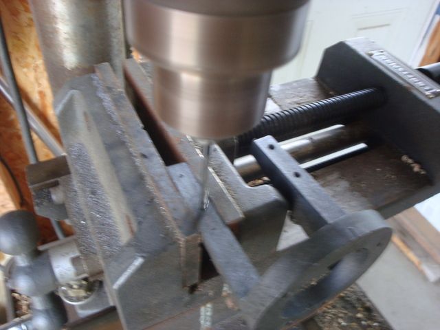
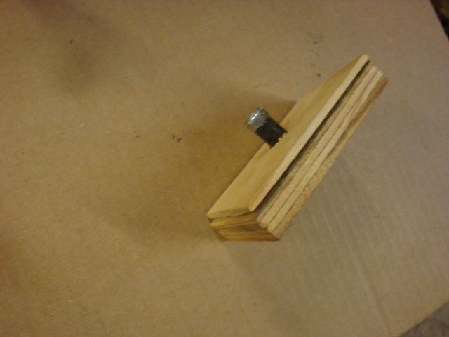
Using a transfer punch through the engine base, I marked the location of the hole on one beam only, then drilled the mount W/a #30 bit & tapped the holes for 8-32 screws.
After tightening the screws, I checked for alignment again.
With the screws tightened down I used the transfer punch on the other mount beam.
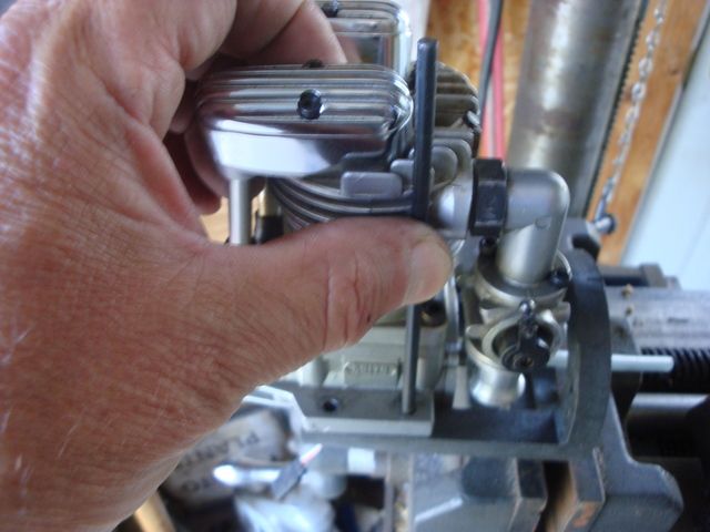
I then repeated the drill & tap operation on the remaining mount beam.
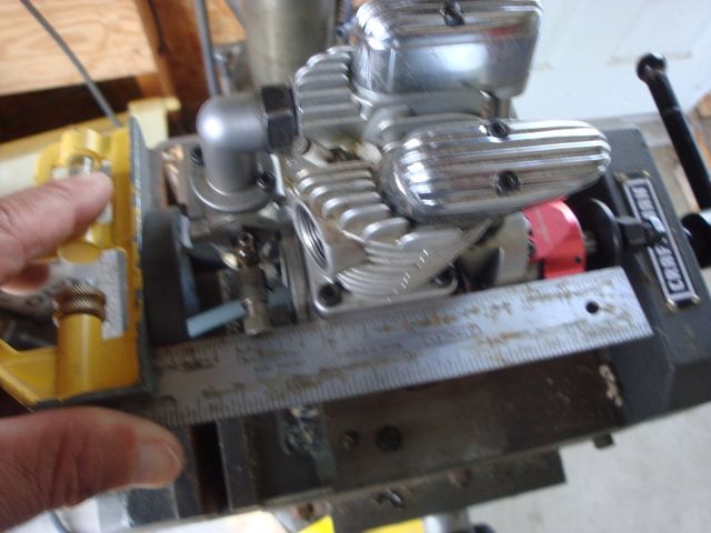
I'm headed to the local HDWE store to get 2 more 8-32 socket head screws. This afternoon I will go about laying out the hole locations on the firewall & go into further detail on the vibration dampening methods I use. The FA-180, while not as bad of a vibrator as a big gas single, it still shakes quite a bit. I have heard of firewall failures W/this bird when the firewall was punished W/a lot of high stress hovering & such W/an FA-180. Since this engine will be producing as much as 1HP more than a stock glow ignition FA-180, I think some added reduction in airframe stress is in order. This is a lightly constructed bird & I don't want to add more weight via heavy reinforcement
Better to reduce airframe stress in the 1st place than add weight by over building to withstand the strain.
Stay tuned.
More on that in the next post.
I started out by clamping the mount in the drill press vise to determine the 6" recommended distance form the firewall to the prop hub. (sorry for the out of focus shot, I didn't have the camera set for close-up)
After establishing the distance, I checked to assure that the engine was square to the base of the mount.
Using a transfer punch through the engine base, I marked the location of the hole on one beam only, then drilled the mount W/a #30 bit & tapped the holes for 8-32 screws.
After tightening the screws, I checked for alignment again.
With the screws tightened down I used the transfer punch on the other mount beam.
I then repeated the drill & tap operation on the remaining mount beam.
I'm headed to the local HDWE store to get 2 more 8-32 socket head screws. This afternoon I will go about laying out the hole locations on the firewall & go into further detail on the vibration dampening methods I use. The FA-180, while not as bad of a vibrator as a big gas single, it still shakes quite a bit. I have heard of firewall failures W/this bird when the firewall was punished W/a lot of high stress hovering & such W/an FA-180. Since this engine will be producing as much as 1HP more than a stock glow ignition FA-180, I think some added reduction in airframe stress is in order. This is a lightly constructed bird & I don't want to add more weight via heavy reinforcement
Better to reduce airframe stress in the 1st place than add weight by over building to withstand the strain.
Stay tuned.
Last edited by SrTelemaster150; 06-23-2015 at 10:57 AM.
06-21-2015, 05:53 PM
#13
Senior Member
Thread Starter
Spent a long day in the garage today. It was raining anyway so a good day to work on the Rascal.
I want to back up a bit first.
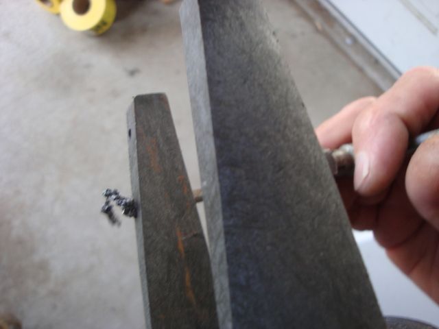
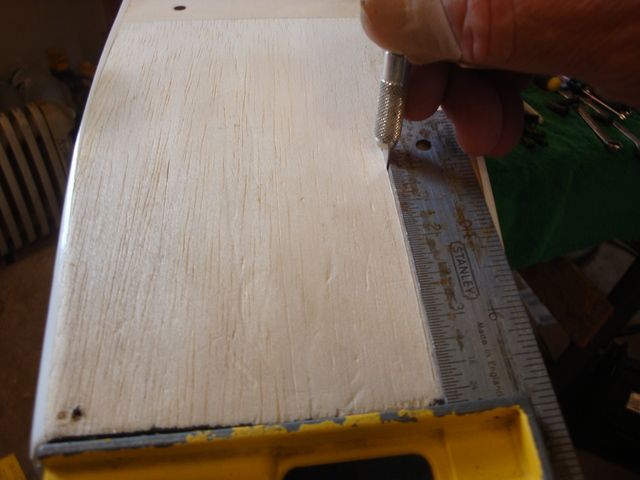
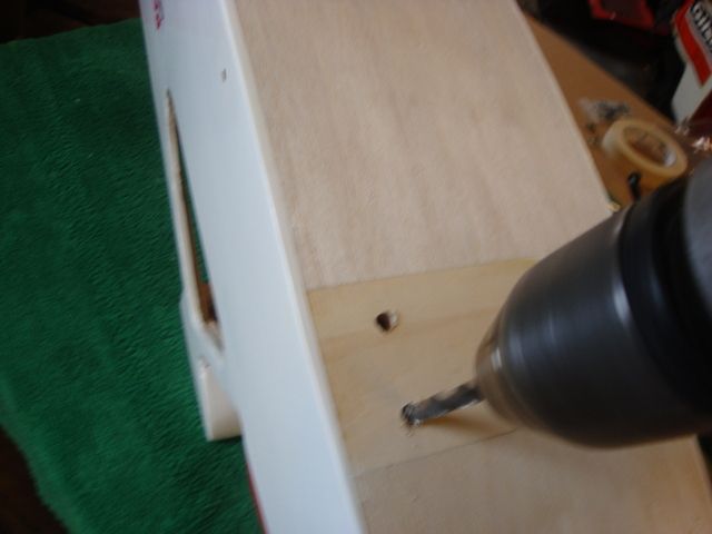
Yesterday, after I had uploaded the pictures, I chucked the 8-32 engine mount screws in the drill press & used a mill file to taper the ends to make a "lead". This will help prevent cross threading in the soft nylon. The nylon is plenty strong to hold the screws given the long thread section.
Now for the progress today.
I started out by laying out the thrust centerline W/masking tape.
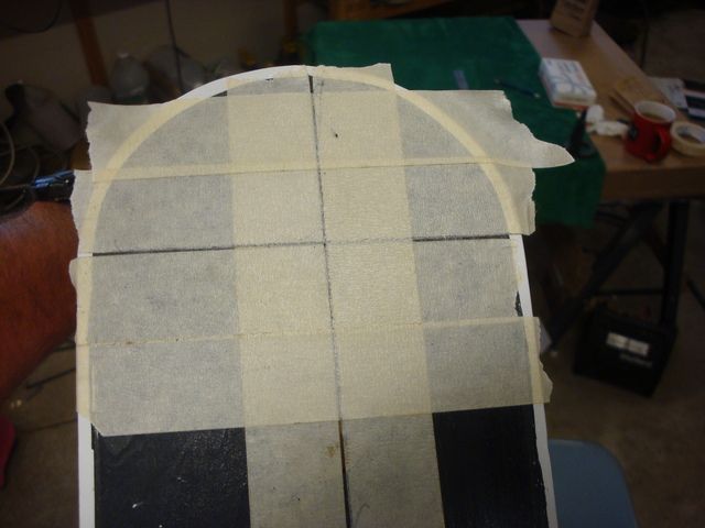
Then, I laid the mount over the centerlines & using the witness marks cast into the mount to locate it properly, I traced around the perimeter. I also cut the masking tape from the square hole that is in the firewall.
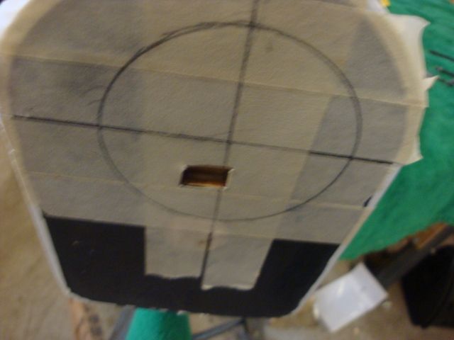
I used a piece of scrap 1/8" aluminum, a stove bolt & a wing nut to clamp the mount in place over the marks made on the tape.
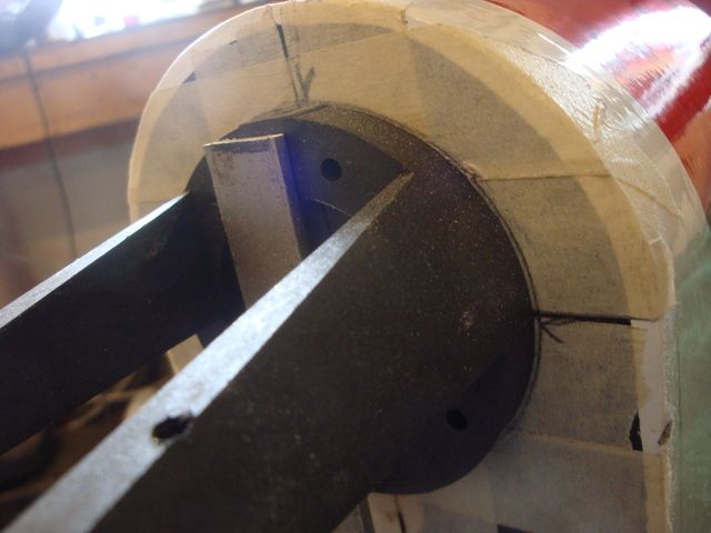
W/the engine clamped in place, I was then able to make cut-outs to the cowl.
As it turned out, I had to rotate the mount a few degrees clockwise to get the cylinder head centered in the bottom of the cowl.
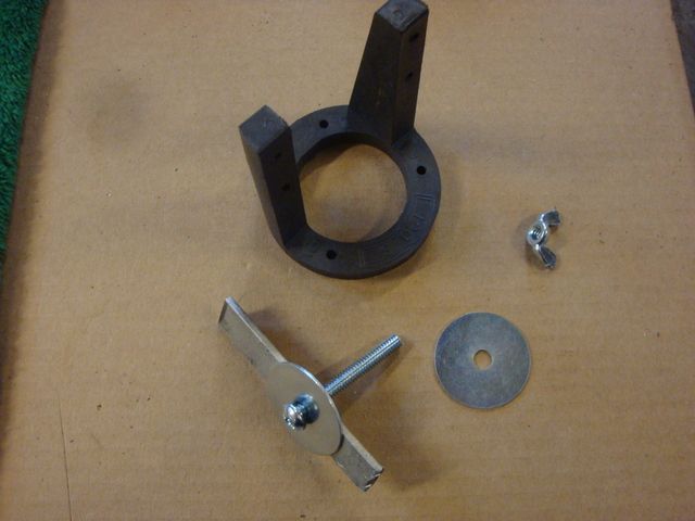
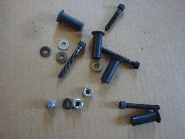
Here are the components needed to make the vibration dampening mount. There's probably about $6 worth of hardware there.
After I drilled the clearance holes form the 10-32 screws through the mount & firewall, I removed the clamped on mount & opened the holes up to 3/8" to clear the rubber well nuts & nylock nuts.
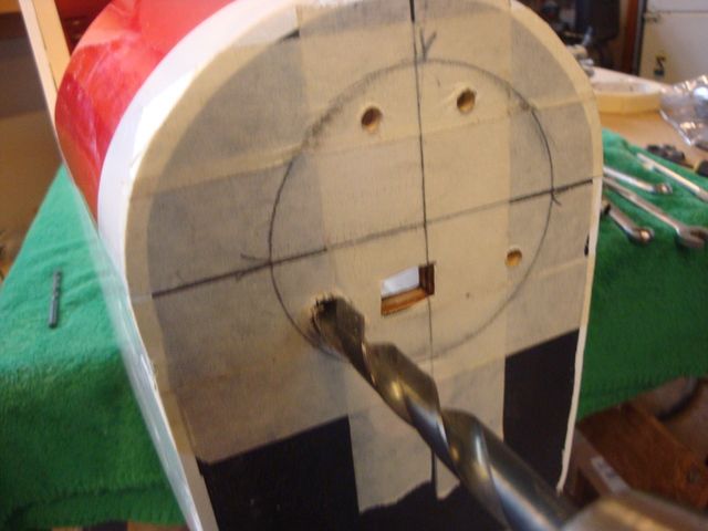
Here is the firewall with the holes prepped for the well nuts. I used a small grindstone to smooth out the edges of the holes.
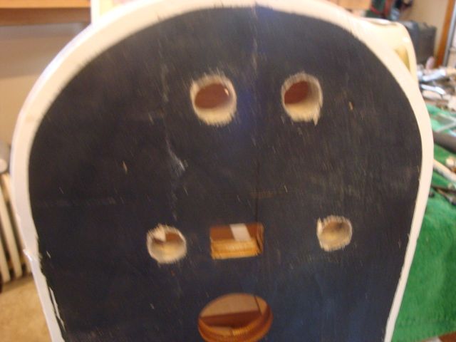
I cut a hatch opening from the firewall to the 1st cross member. This will be used to house the CDI module as well as allow access to the back of the firewall to hold the nuts as the mount is tightened down.
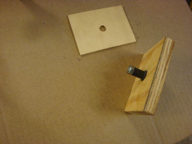
Somehow I lost the PIX of the assembled mount before I inserted it into the firewall. I did a mock-up W/some plywood. The 3/8" ply represents the mount, the 1/8" the firewall.
First you assemble the bolt & well nut & screw the nylock nut down finger snug onto the end of the well nut. You don't want to swell the side of the well nut. Just assemble finger snug.
Insert the assembled mount W/the well nuts & nyloc nuts into the prepped holes in the firewall. The nyloc nuts will be slightly tight so I used a plastic mallet to tap the screws through the firewall working each one a little at a time until the mount slips up against the firewall.
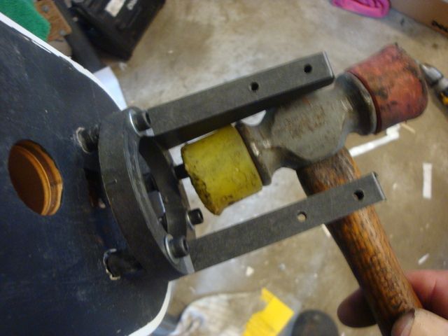
Now all you need to do is reach through the hatch to hold the nyloc nuts W/a 3/8" wrench while you tighten down the mount screws for the desired resilience in the mount as you hold the mount firmly against the firewall. I have my 180 tightened down so that there is perhaps 1/8" of movement @ the spinner when I grasp the engine firmly & twist it side to side. I will adjust the firmness as needed after the engine is fired up. The way the Dave Brown mount is situated, a ball end Allan wrench will access the mount bolts W/the engine mounted.
When tightened down snuggly, the rubber expands in the hole & mushrooms out behind the firewall to securely lock the assembly together.
Make sure there is @ least 3/8" of rubber protruding from the firewall before the nut is tightened down.
More to follow
I want to back up a bit first.
Yesterday, after I had uploaded the pictures, I chucked the 8-32 engine mount screws in the drill press & used a mill file to taper the ends to make a "lead". This will help prevent cross threading in the soft nylon. The nylon is plenty strong to hold the screws given the long thread section.
Now for the progress today.
I started out by laying out the thrust centerline W/masking tape.
Then, I laid the mount over the centerlines & using the witness marks cast into the mount to locate it properly, I traced around the perimeter. I also cut the masking tape from the square hole that is in the firewall.
I used a piece of scrap 1/8" aluminum, a stove bolt & a wing nut to clamp the mount in place over the marks made on the tape.
W/the engine clamped in place, I was then able to make cut-outs to the cowl.
As it turned out, I had to rotate the mount a few degrees clockwise to get the cylinder head centered in the bottom of the cowl.
Here are the components needed to make the vibration dampening mount. There's probably about $6 worth of hardware there.
After I drilled the clearance holes form the 10-32 screws through the mount & firewall, I removed the clamped on mount & opened the holes up to 3/8" to clear the rubber well nuts & nylock nuts.
Here is the firewall with the holes prepped for the well nuts. I used a small grindstone to smooth out the edges of the holes.
I cut a hatch opening from the firewall to the 1st cross member. This will be used to house the CDI module as well as allow access to the back of the firewall to hold the nuts as the mount is tightened down.
Somehow I lost the PIX of the assembled mount before I inserted it into the firewall. I did a mock-up W/some plywood. The 3/8" ply represents the mount, the 1/8" the firewall.
First you assemble the bolt & well nut & screw the nylock nut down finger snug onto the end of the well nut. You don't want to swell the side of the well nut. Just assemble finger snug.
Insert the assembled mount W/the well nuts & nyloc nuts into the prepped holes in the firewall. The nyloc nuts will be slightly tight so I used a plastic mallet to tap the screws through the firewall working each one a little at a time until the mount slips up against the firewall.
Now all you need to do is reach through the hatch to hold the nyloc nuts W/a 3/8" wrench while you tighten down the mount screws for the desired resilience in the mount as you hold the mount firmly against the firewall. I have my 180 tightened down so that there is perhaps 1/8" of movement @ the spinner when I grasp the engine firmly & twist it side to side. I will adjust the firmness as needed after the engine is fired up. The way the Dave Brown mount is situated, a ball end Allan wrench will access the mount bolts W/the engine mounted.
When tightened down snuggly, the rubber expands in the hole & mushrooms out behind the firewall to securely lock the assembly together.
Make sure there is @ least 3/8" of rubber protruding from the firewall before the nut is tightened down.
More to follow
Last edited by SrTelemaster150; 06-22-2015 at 04:30 AM. Reason: Ad Title
06-21-2015, 06:10 PM
#14
Senior Member
Thread Starter
After getting the engine mounted & the cowl cut for clearances, I went after the landing gear.
I wanted to use 10-32 nylon wing bolts to anchor the main gear for break-away action in case of a botched landing.
After removing the metric factory "T" nuts, I drilled out the holes to 1/4" to accommodate the 10-32 "T" nuts. I pulled them in W/some steel 10-32 bolts before substituting the nylon examples.
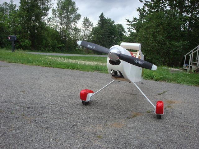
After assembling the wheels/pants as well as installing the tail wheel, she can now stand on her own 3 feet.
I wanted to use 10-32 nylon wing bolts to anchor the main gear for break-away action in case of a botched landing.
After removing the metric factory "T" nuts, I drilled out the holes to 1/4" to accommodate the 10-32 "T" nuts. I pulled them in W/some steel 10-32 bolts before substituting the nylon examples.
After assembling the wheels/pants as well as installing the tail wheel, she can now stand on her own 3 feet.
06-22-2015, 08:13 AM
#15
Foodstick, I love your green and white Rascal! I built the Rascal C and used the same color scheme. I added some gold penstripping where the green meets the white and around the windows it really popped that way.
Telemaster, I like to drill and tap the engine mount too but I'm a belt and suspenders type and add a nylock or a nut and split washers to the bottom.
Mike
Telemaster, I like to drill and tap the engine mount too but I'm a belt and suspenders type and add a nylock or a nut and split washers to the bottom.
Mike
06-22-2015, 09:32 AM
#16
Senior Member
Thread Starter
In the past I have used nylocs on the bottom (top actually since the engine will be mounted inverted) of the beam. I'm going to monitor the mount bolts closely & will add the nyloks if needed. The split washers won't do much since the bottom of the beam is tapered. I already have them under the socket head.
06-22-2015, 02:36 PM
#18
Senior Member
Thread Starter
Not only jugs poking out, but carburetors & velocity stacks!
https://www.youtube.com/watch?v=vdmLu13UJzs
Last edited by SrTelemaster150; 06-22-2015 at 02:45 PM.
06-22-2015, 06:51 PM
#19
I was so interested in one, they had one at the SIG fly in in the stash of planes for sale. I just had to remind myself, I already have more planes than I can fly at any one time. Besides, it NEEDS a twin on it to look the part. That is one big plane! I dont have one(Stupid me passed up a 300 for $300)
07-14-2015, 01:18 PM
#20
Senior Member
Thread Starter
The first step is to mount a Perry Oscillating pump to the back of the crankcase. I am going to mount my 32oz fuel tank a bit aft so that it is centered on the CG. This will allow a constant CG in level flight regardless of the fuel level in the tank. Muffler pressure will still be employed & the pump will assist making fuel level & tank location less critical. I employed the same set-up on my Dynaflite PT-19 & it would pull through giants loops W/O a hick-up.
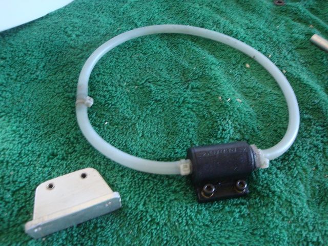
Here is the pump & bracket I made from some 1/8" aluminum angle.
I avoid using the back plate screws as a mount opting to make "studs" & employ nylock nuts. I started by threading some old nuts on the 3mm X 20mm socket head screws & bottoming them out while using red Lock-Tite on the screws to anchor them securely.
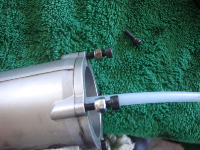
After cutting off the heads W/a diamond wheel on my Dremel, I smoothed the ends of the studs to remove any burrs & backed the nuts off to further clean the threads. The nuts were discarded since the heat of cutting off the heads melted the nylock inserts.
I then installed the bracket W/new nylock nuts. Note that the 20mm length was perfect to allow just enough of the stud to protrude from the nuts to assure the nylock insert was engaged fully.
Next step is the Ignition module installation.
Here is the pump & bracket I made from some 1/8" aluminum angle.
I avoid using the back plate screws as a mount opting to make "studs" & employ nylock nuts. I started by threading some old nuts on the 3mm X 20mm socket head screws & bottoming them out while using red Lock-Tite on the screws to anchor them securely.
After cutting off the heads W/a diamond wheel on my Dremel, I smoothed the ends of the studs to remove any burrs & backed the nuts off to further clean the threads. The nuts were discarded since the heat of cutting off the heads melted the nylock inserts.
I then installed the bracket W/new nylock nuts. Note that the 20mm length was perfect to allow just enough of the stud to protrude from the nuts to assure the nylock insert was engaged fully.
Next step is the Ignition module installation.
07-14-2015, 01:22 PM
#21
Senior Member
Thread Starter
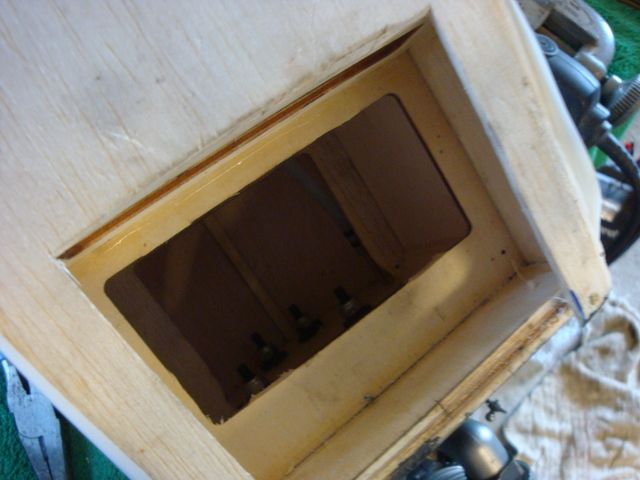
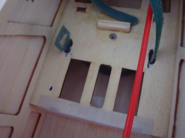
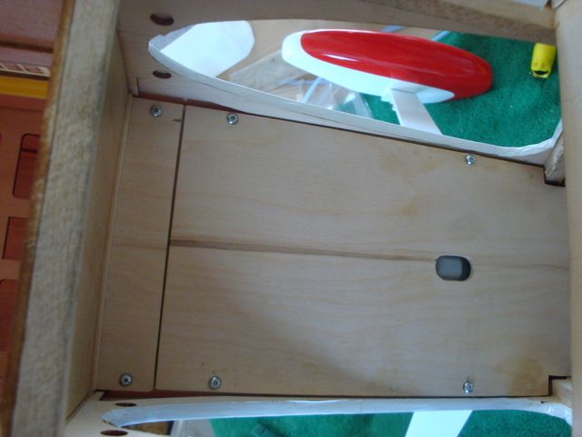
Having previously cut a hatch access in the bottom of the fuselage, a bit more surgery was required to allow easier access to the area behind the firewall. I cut the webs from the lite ply horizontal brace.
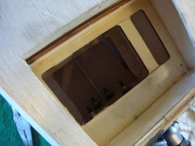
This, along with widening the hatch to the width of the cowl opening allowed plenty of room for access.
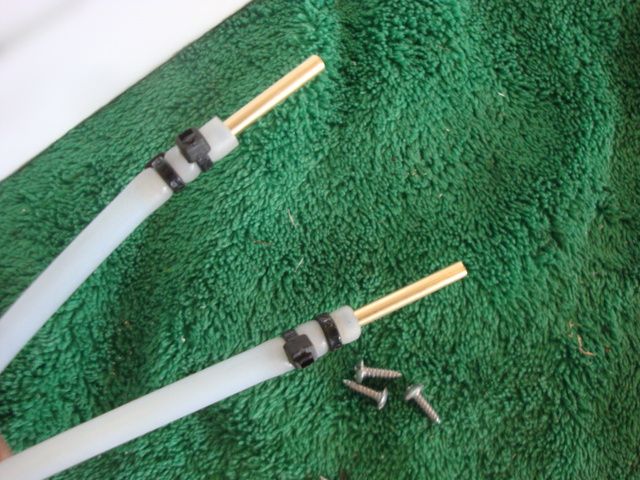
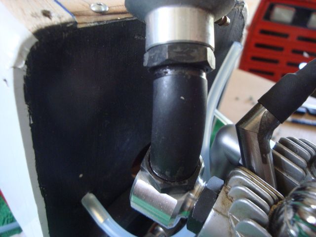
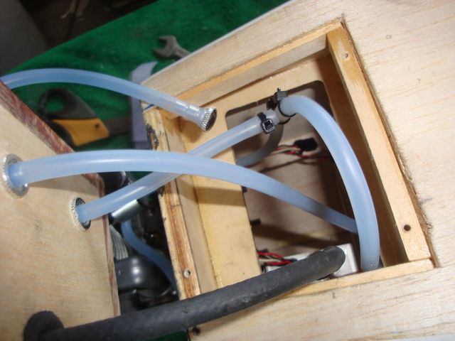
I also installed firewall penetrations for the fuel line & muffler pressure in at this time. I cut 1 1/2" long sections of 1/8" brass tubing & inserted them 5/8" into the medium fuel line & secured them W/double cable ties. 1/8" holes were drilled in the appropriate locations in the firewall & an Allen socket driver was used to fish the tube into the holes from behind. I secured the tube penetrations W/CA.
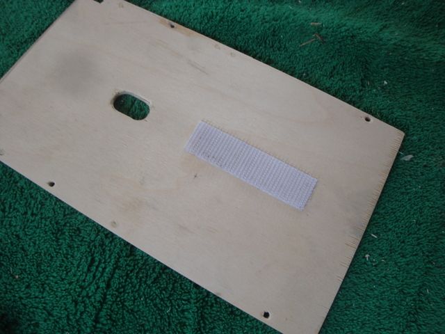
Having that out of the way, I finalized the location of the ignition module to put the least amount of stress on the spark lead as possible. I applied three pieces of hook section Velcro to the inside of the fuselage on the port side. I covered a generous section, much larger than actually needed to assure that I would not pull edges up when removing the module. The module was wrapped in such a way that the loop sections extended around the edges for similar reasons. Once the module is pressed into the hook sections of Velcro, it makes for a secure yet vibration isolating mount. That is a C&H Electronics Mk-I Syncro-Spark module made in 1997. It had only been used for bench testing. This will be its 1st ride in an airframe.
I used some 1/4" X 3/8" basswood to frame the opening to restore some of the structural rigidity that was compromised by cutting the hatch opening & web removal.
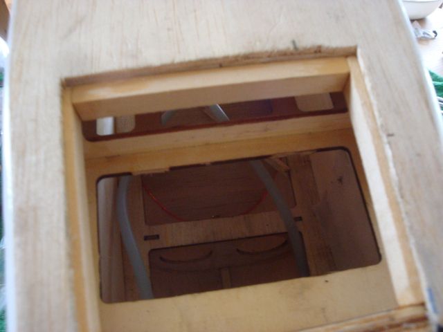
I am employing 1/8" birch ply for the hatch & when it is anchored W/2 screws in the bottom of the firewall & 2 more in the rear cross member that was added, structural rigidity should be as good or better than original. Note the rubber grommet at the spark lead penetration.
Stay tuned for the Installation & plumbing of the 32oz Sullivan tank W/overflow lines for both 16oz & 32oz fill.
This, along with widening the hatch to the width of the cowl opening allowed plenty of room for access.
I also installed firewall penetrations for the fuel line & muffler pressure in at this time. I cut 1 1/2" long sections of 1/8" brass tubing & inserted them 5/8" into the medium fuel line & secured them W/double cable ties. 1/8" holes were drilled in the appropriate locations in the firewall & an Allen socket driver was used to fish the tube into the holes from behind. I secured the tube penetrations W/CA.
Having that out of the way, I finalized the location of the ignition module to put the least amount of stress on the spark lead as possible. I applied three pieces of hook section Velcro to the inside of the fuselage on the port side. I covered a generous section, much larger than actually needed to assure that I would not pull edges up when removing the module. The module was wrapped in such a way that the loop sections extended around the edges for similar reasons. Once the module is pressed into the hook sections of Velcro, it makes for a secure yet vibration isolating mount. That is a C&H Electronics Mk-I Syncro-Spark module made in 1997. It had only been used for bench testing. This will be its 1st ride in an airframe.
I used some 1/4" X 3/8" basswood to frame the opening to restore some of the structural rigidity that was compromised by cutting the hatch opening & web removal.
I am employing 1/8" birch ply for the hatch & when it is anchored W/2 screws in the bottom of the firewall & 2 more in the rear cross member that was added, structural rigidity should be as good or better than original. Note the rubber grommet at the spark lead penetration.
Stay tuned for the Installation & plumbing of the 32oz Sullivan tank W/overflow lines for both 16oz & 32oz fill.
08-08-2015, 05:56 PM
#22
Senior Member
Thread Starter
Things have been crazy around the homestead & I haven't been able to get much done. Over the last 2 days I made a little progress.
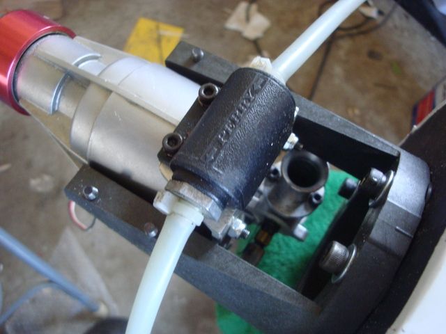
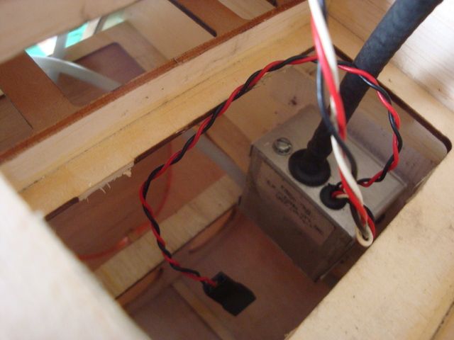
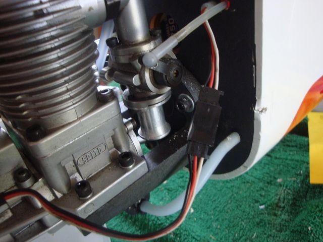
I wanted to make a vibration proof penetration of the firewall for the Hall Affect lead. Since the lead itself was longer than needed to reach the firewall, I clipped it & installed new plastic Futaba "J" connectors.
Before pushing the terminals into the plastic portion of the connector, I threaded them through some fuel tubing & pushed it through the firewall.
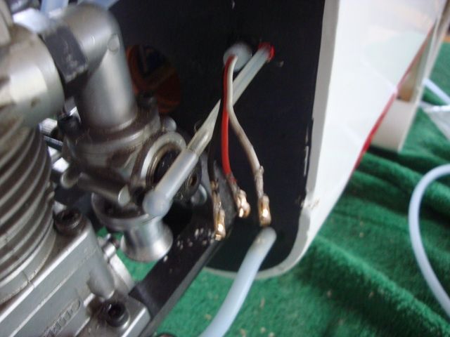
After installing the plastic ends the connector will tuck neatly in behind the carburetor.
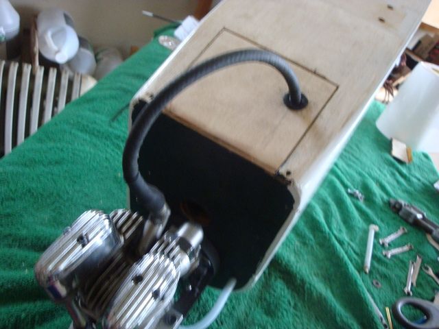
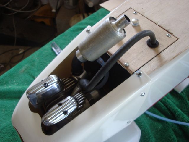
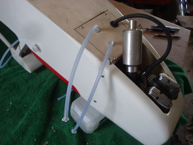
I also was able to employ a 90* adaptor from Turboheader to make a neat, tidy muffler installation through the bottom of the cowl opening.
Next we'll move on to the fuel tank plumbing.
I wanted to make a vibration proof penetration of the firewall for the Hall Affect lead. Since the lead itself was longer than needed to reach the firewall, I clipped it & installed new plastic Futaba "J" connectors.
Before pushing the terminals into the plastic portion of the connector, I threaded them through some fuel tubing & pushed it through the firewall.
After installing the plastic ends the connector will tuck neatly in behind the carburetor.
I also was able to employ a 90* adaptor from Turboheader to make a neat, tidy muffler installation through the bottom of the cowl opening.
Next we'll move on to the fuel tank plumbing.
08-08-2015, 05:58 PM
#23
Senior Member
Thread Starter
Now we address the fuel tank & plumbing the duel level overflow lines.
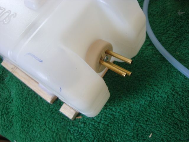
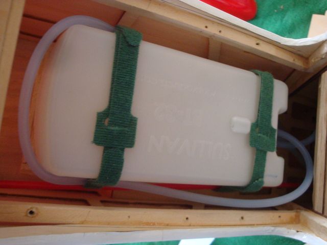
I uses 3 tank lines. The 2 on the top are the standard clunk & vent lines but the one in the center bottom is an overflow line that barely goes into the tank just beyond the stopper. Its purpose is to allow 1/2 of the 32oz tank to be filled to a consistent 16oz.
The vent line is "T"ed & the 2 lines exit the hatch under the chin.
The rear line overflows at just a smidge over 16oz, the front line is the full 32oz overflow through the vent.
I started making provision to secure the tank over the CG by using a Dremel tool to make oblong holes in the deck to allow a Velcro strap to be fished through for securing the tank. I also glued a 5/16" square block that will serve as the front limit to keep the fuel tank from shifting forward.
I made tray from 1/32" birch ply with more 5/16" block to cradle the rear & sides of the tank.
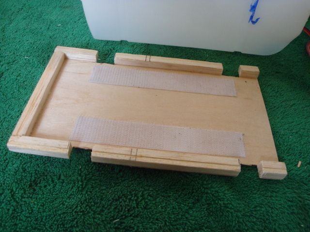
A basswood "key" block was fashioned to fit loosely into an existing cutout in the deck.
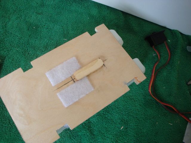
Sticky back Velcro is used to help secure the tank from excess shifting.
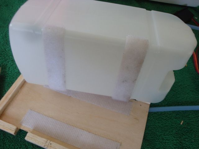
Another Velcro strap is used to secure the back of the tray to the tank. the back of the tray floats off the end of the deck.
Then, the Velcro strap previously fished under the deck to tie the whole thing down. Note that the vent line is looped behind the tank to prevent fuel siphoning when the plane is in a nose down attitude.
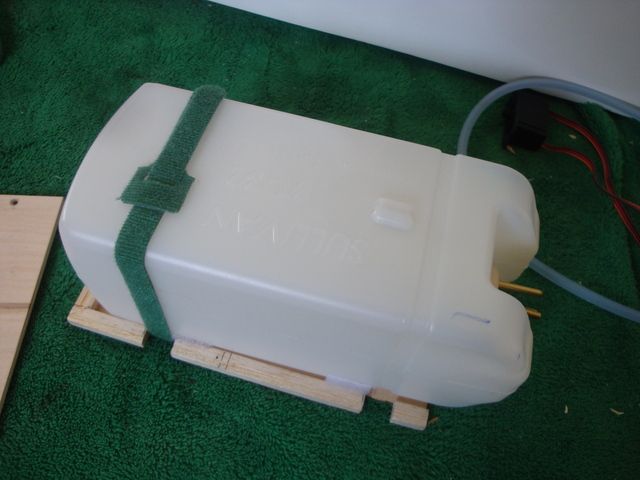
I fashioned a top plate from 1/8" lite ply to hold the whole thing down. Note the cut out for the vent blister.
Finally, the plate is secured W/#4 button head screws into the basswood rails. The deck is too long to be fished in & out of the cabin, so a short section of deck was fashioned & screw applied at the rear.
I uses 3 tank lines. The 2 on the top are the standard clunk & vent lines but the one in the center bottom is an overflow line that barely goes into the tank just beyond the stopper. Its purpose is to allow 1/2 of the 32oz tank to be filled to a consistent 16oz.
The vent line is "T"ed & the 2 lines exit the hatch under the chin.
The rear line overflows at just a smidge over 16oz, the front line is the full 32oz overflow through the vent.
I started making provision to secure the tank over the CG by using a Dremel tool to make oblong holes in the deck to allow a Velcro strap to be fished through for securing the tank. I also glued a 5/16" square block that will serve as the front limit to keep the fuel tank from shifting forward.
I made tray from 1/32" birch ply with more 5/16" block to cradle the rear & sides of the tank.
A basswood "key" block was fashioned to fit loosely into an existing cutout in the deck.
Sticky back Velcro is used to help secure the tank from excess shifting.
Another Velcro strap is used to secure the back of the tray to the tank. the back of the tray floats off the end of the deck.
Then, the Velcro strap previously fished under the deck to tie the whole thing down. Note that the vent line is looped behind the tank to prevent fuel siphoning when the plane is in a nose down attitude.
I fashioned a top plate from 1/8" lite ply to hold the whole thing down. Note the cut out for the vent blister.
Finally, the plate is secured W/#4 button head screws into the basswood rails. The deck is too long to be fished in & out of the cabin, so a short section of deck was fashioned & screw applied at the rear.
08-09-2015, 01:08 PM
#24
Senior Member
Thread Starter
The throttle & rudder servos are pretty much as per the plans.
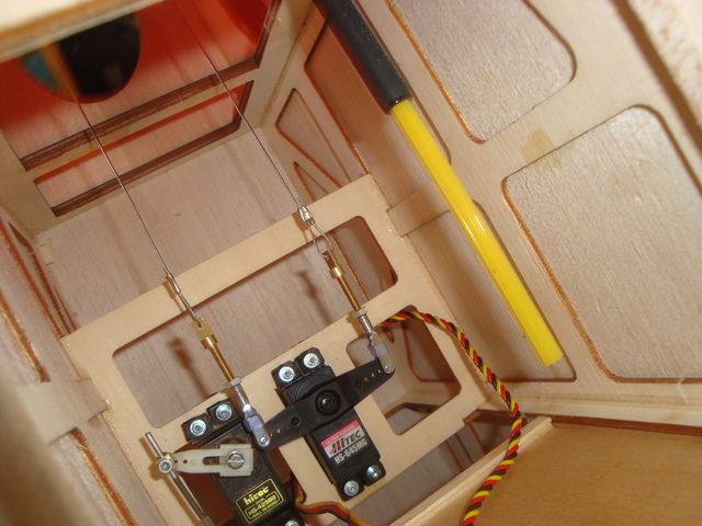
I deviated a bit on the rather heavy high torque metal gear elevator servo opting to mount it amidships rather than in the rear of the fuselage under the horizontal stabilizer. A Sullivan high stress 4-40 flexible pushrod was employed & it was routed high in the fuselage to run next to one of the stringers for aesthetic purposes. This required a mount to be fabricated high under the wing saddle. I used some 3/8" x 1/2" basswood to fabricate a double "H" section frame.
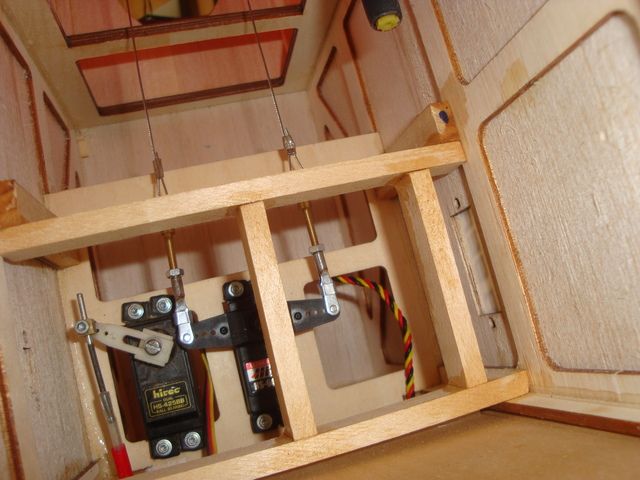
The spacing was such that the pushrod centers just inboard of the last hole in the heavy duty servo arm.
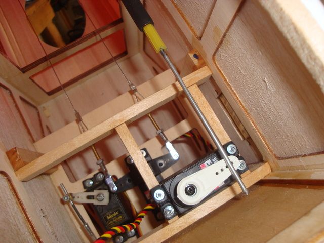
In the morning I'll get the horizontal & vertical stabilizers mounted, install the control surfaces, finish up the pull/pull cables on the rudder, establish the finished length of the elevator pushrod & solder a clevis on the servo end.
It will then be time to tackle the wings & I have several projects/modifications to do. The servo trays need to be modified slightly for the low profile 77 oz in servos, I need to fabricate a custom "Y" harness for the flaps, custom length servo extensions for the ailerons & I need to wire one of the flap servos for reverse operation to eliminate the need for a servo reversing "Y" harness.
I deviated a bit on the rather heavy high torque metal gear elevator servo opting to mount it amidships rather than in the rear of the fuselage under the horizontal stabilizer. A Sullivan high stress 4-40 flexible pushrod was employed & it was routed high in the fuselage to run next to one of the stringers for aesthetic purposes. This required a mount to be fabricated high under the wing saddle. I used some 3/8" x 1/2" basswood to fabricate a double "H" section frame.
The spacing was such that the pushrod centers just inboard of the last hole in the heavy duty servo arm.
In the morning I'll get the horizontal & vertical stabilizers mounted, install the control surfaces, finish up the pull/pull cables on the rudder, establish the finished length of the elevator pushrod & solder a clevis on the servo end.
It will then be time to tackle the wings & I have several projects/modifications to do. The servo trays need to be modified slightly for the low profile 77 oz in servos, I need to fabricate a custom "Y" harness for the flaps, custom length servo extensions for the ailerons & I need to wire one of the flap servos for reverse operation to eliminate the need for a servo reversing "Y" harness.