


Laser Cut DB40 Build
 12-08-2013 | 07:44 AM
#1

Thread Starter
Member
Joined: Nov 2012
Posts: 68
Likes: 0
Received 0 Likes
on
0 Posts
From: Center Point, AL
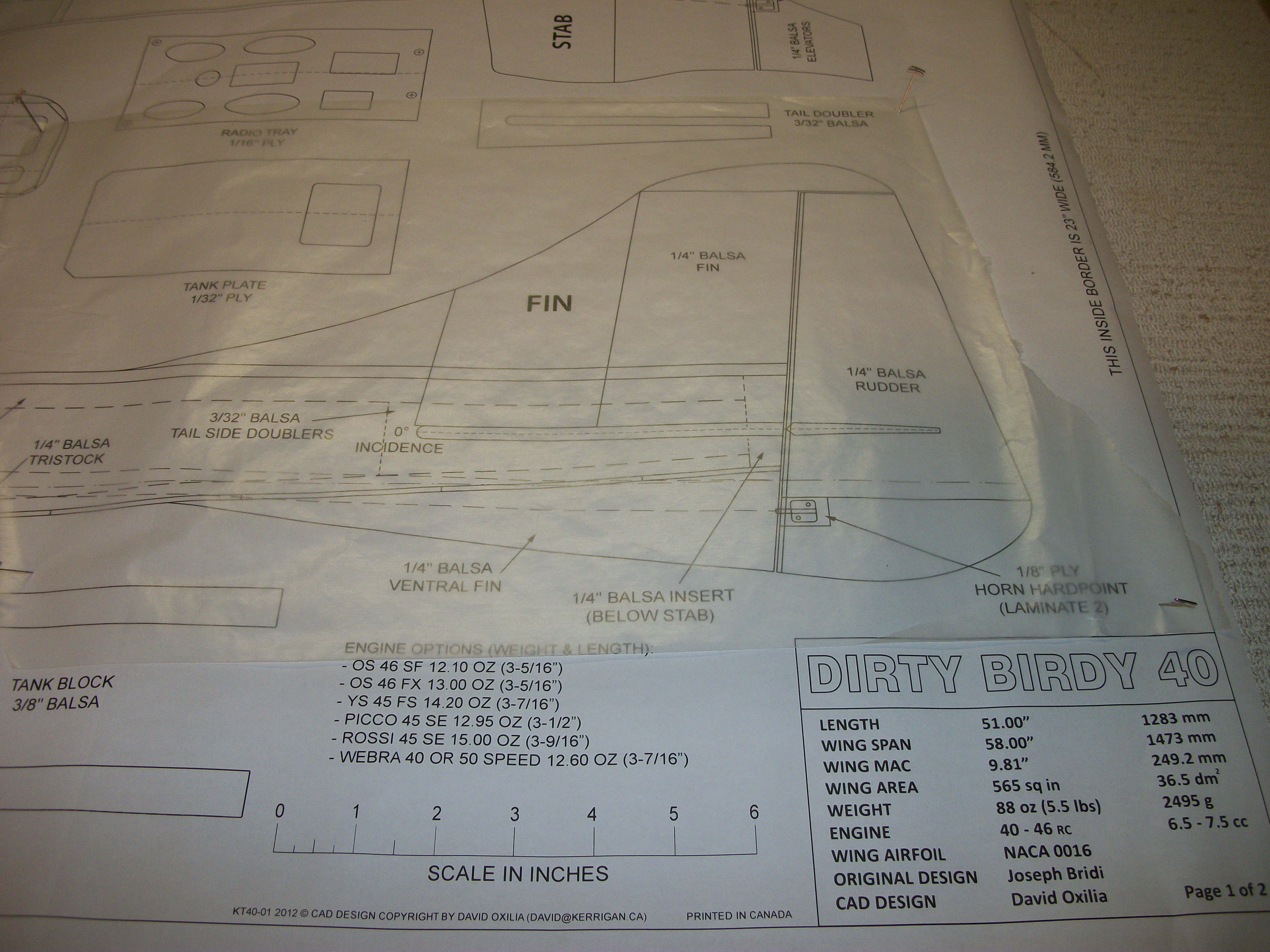
This is the laser cut short kit by David Oxilia I am building this winter. The kit has been on a shelf waiting for my Super Chipmunk to be finished, but because my builds are generally long, this might take a while. I've always wanted to fly pattern and love the looks of the planes, when I got a chance to buy this I jumped at it and plan on flying this in CPA events with a pipe and retracts using a Aviastar .46 for power... yes, you read correct...it is big and heavy and made in China, but I have one in the box so it will see some time in the nose until I can get a more traditional engine. I am taking donations for the YS now though and can be talked out of it...
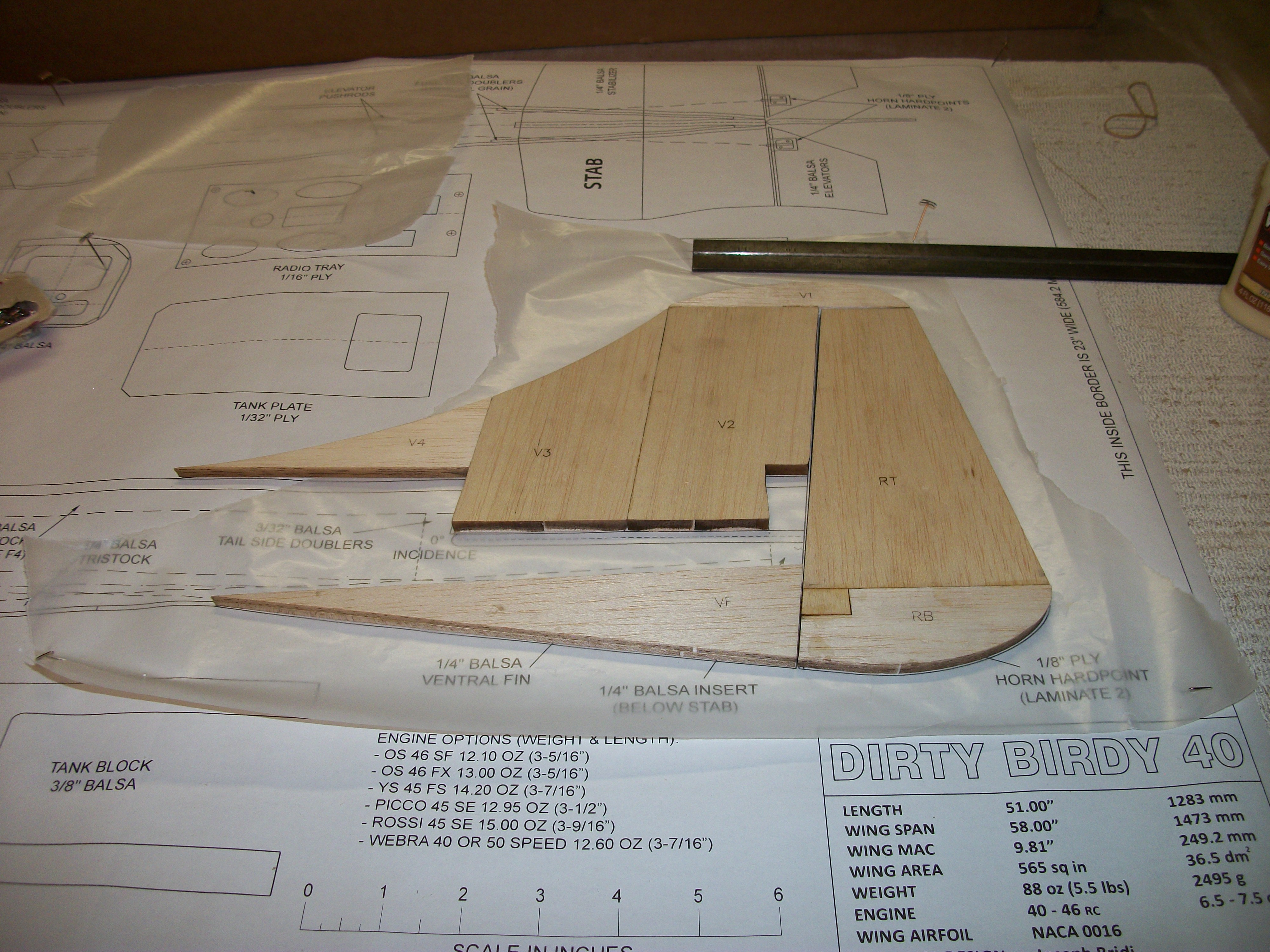
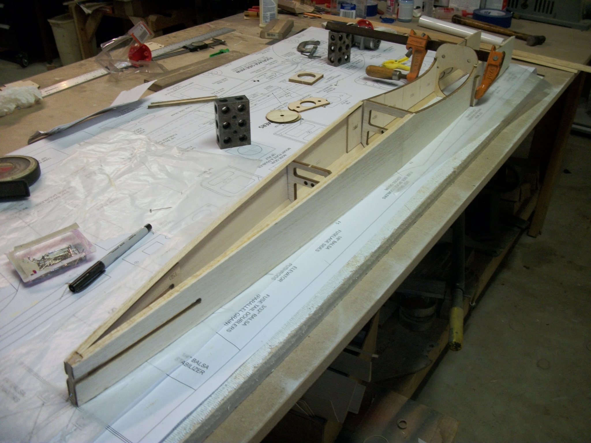
I started with the vertical stab and rudder just because the parts were literally falling out of the stock sheet. I found that all of the cuts are clean and most need no help coming off the sheet at all, a little sand paper clean up and they are ready to glue.
Next, I laminated the side panels and glued the tri-stock in place. Once the glue set I set the sides up and sanded them to level everything up.
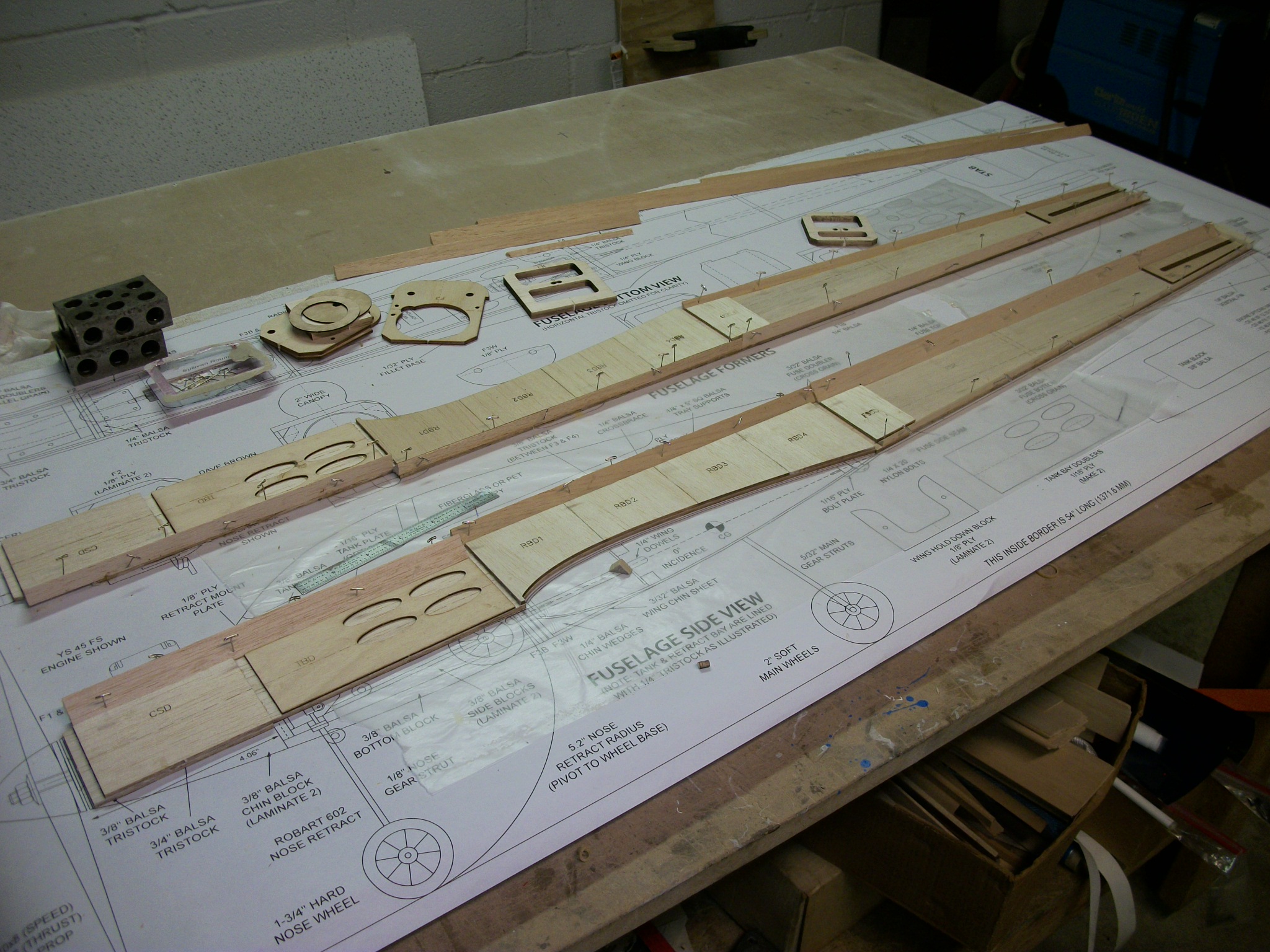
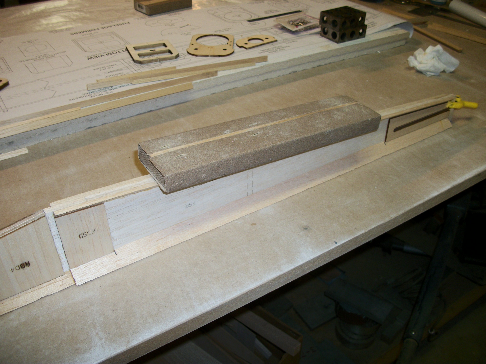
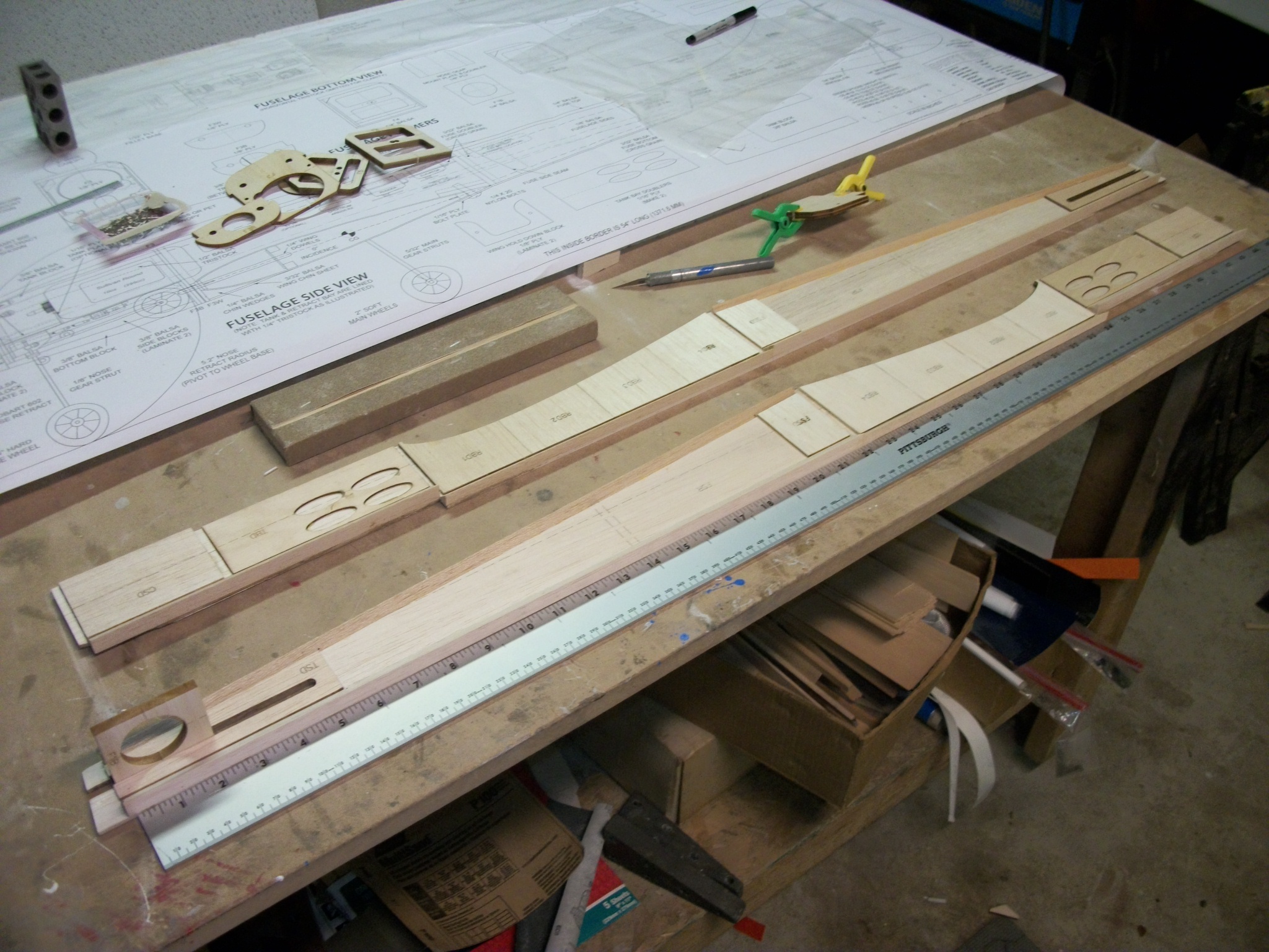
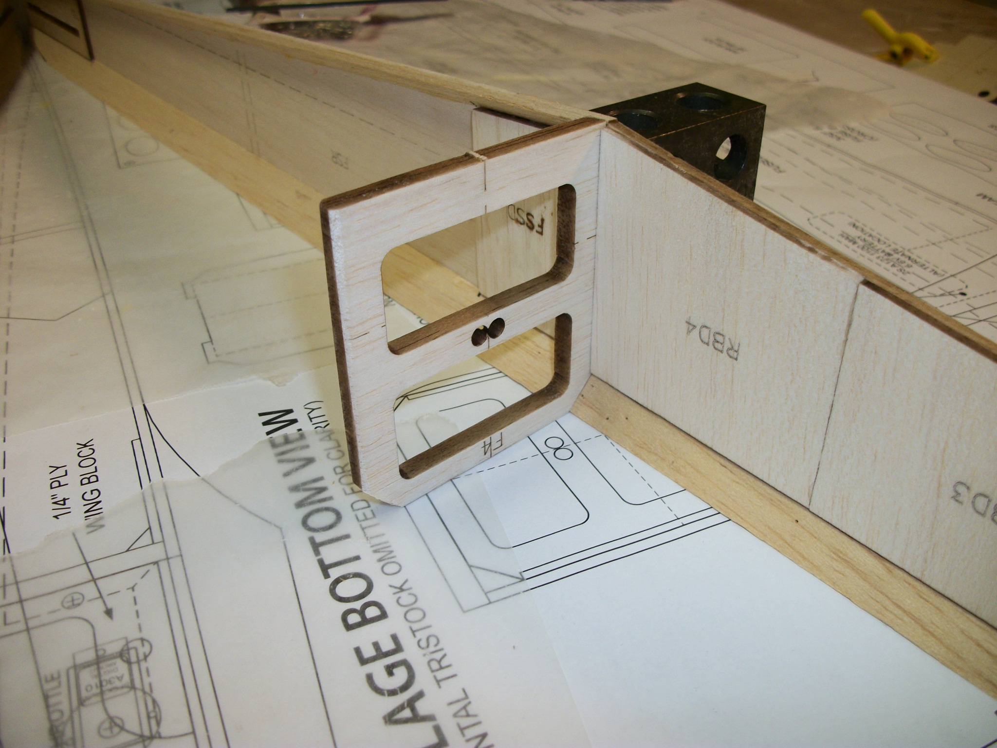
Once I was satisfied with the panels I test fit the bulkheads and made a balsa wedge for joining at the aft end. After the glue had set I then wet the panels with water and pulled them together to set the shape as shown in the image on the right.
I started with the vertical stab and rudder just because the parts were literally falling out of the stock sheet. I found that all of the cuts are clean and most need no help coming off the sheet at all, a little sand paper clean up and they are ready to glue.
Next, I laminated the side panels and glued the tri-stock in place. Once the glue set I set the sides up and sanded them to level everything up.
Once I was satisfied with the panels I test fit the bulkheads and made a balsa wedge for joining at the aft end. After the glue had set I then wet the panels with water and pulled them together to set the shape as shown in the image on the right.
 12-08-2013 | 08:12 AM
#2

My Feedback: (3)
Dave,
great to see you at it and thanks for showing us your build.
One issue I ran into when framing up the fuse was the cowl side doublers (CSD). I found it a bit tricky to pull the nose together on to F1B, the nose ring backplate, with the doublers already bonded to the sides. If they aren't already glued and for other builders, I'd suggest bringing the sides together on to F1B and adding the doublers afterward. A little hot water on the outsides of the doublers will help them curve to the inner contour of the sides. After they're in place, the tristock can be added to the cowl area. I see that you have the cowl top tristock in place already and that will make closing up the cowl tricky as well. You can just sand it off if it's giving you trouble and then add it back in once the sides are pulled together.
Depending on the engine/motor installation, the cowl can be built up in a number of ways so I won't elaborate further on it. However, with a 2-stroke, it is generally either upright or side mounted depending on where one wants the muffler/pipe to run. Fuel draw shouldn't be an issue with either type of mount pattern.
Although I changed the radio tray to 1/8" lite ply in the production run kits, the plans show it as being 1/16" ply. The lite ply was just more practical and weighs the same. The extra thickness will have to be taken into account when installing the tray in the model so that the elevator servo base is flush with the fuse top (paper thickness offset) and the pushrod sleeves align with the holes in F4. My proto kit uses the 1/16" tray and when I tried to use the 1/8" on the same tray rails, it put the servo output to high up for proper pushrod alignment. I went back to the 1/16" and just backed the servo mount point with some 1/8" ply for the servo screws. You might want to do this regardless with the lite ply try for a little added servo screw retention. Note that this is required regardless for the rudder servo which must be offset from the elevator servo so the P-P cables clear the pushrods.
I'd suggest using Sullivan CF pushrods for the elevators but plastic sheath pushrods are fine too.
Looking good!
David
Last edited by doxilia; 12-08-2013 at 08:41 AM.
12-08-2013 | 08:37 AM
#3
My Feedback: (3)
Another little detail which I don't believe made it into your kit run is the tank mount. There is the thin 1/32" ply tray to separate out the tank compartment from the retract bay. During my build, I decided that I didn't need this separation and made the access and fit of the gear in that area more complicated. Instead, I made a simply rectangular 1/16" ply bulkhead of sorts to support the Sullivan round tank neck. This works well with tanks that have a protruding neck such as the RST. One can make the bulkhead so that it closes off the fuel line "box" under the retract plate extending to the fuse top or simply square it off at the height of the tristock. I left mine open so that I could have access to the fuel line area (wanted to make sure if a spill did happen, I could get to the area).
In short, the thin bulkhead gets epoxied to the back end of the retract plate and the tristock on the bottom (really the top). The fuel tank is then simply slid into place and held there by a rubber band and two eyelets screwed into the back of F3 (or whatever other system you can fashion). A ring of silicon caulk can be added between the tank and its bulkhead plate to help dampen vibration. As a side benefit, the bulkhead supports the rear of the retract plate. I added tristock to the sides of the plate and bulkhead for a stiff retract/tank box.
The picture below shows better what I'm talking about.
I hope these tips/ideas are of some help.
David
12-08-2013 | 11:14 AM
#4
Thread Starter
Member
Joined: Nov 2012
Posts: 68
Likes: 0
Received 0 Likes
on
0 Posts
From: Center Point, AL
Hi David
Thanks for the information regarding the tank installation and sides, I've already glued the CSD to the sides so I'll try and bend it over a couple day period by keeping it pulled together and wetting it till it pulls together.
Dave
Thanks for the information regarding the tank installation and sides, I've already glued the CSD to the sides so I'll try and bend it over a couple day period by keeping it pulled together and wetting it till it pulls together.
Dave
12-12-2013 | 04:35 PM
#5
Thread Starter
Member
Joined: Nov 2012
Posts: 68
Likes: 0
Received 0 Likes
on
0 Posts
From: Center Point, AL
This is how I'm trying to pull the sides to the spinner plate. I've sprayed h2o inside and out with pressure from the clamp to pull it together. I'll let it dry and close it some more to see what happens.
12-13-2013 | 11:54 AM
#6
My Feedback: (3)
Dave,
Coming along nicely!
Make sure you use plenty of H20 (hot preferably) and/or windex/ammonia to get the outside of the wood nice and elastic. The biggest obstacle is likely the tristock you have in the cowl so make sure it doesn't split off from the sides behind the FW. Also, you will want to bring the sides up to the F1B 1/4" rectangular balsa former. F1B glues in between the fuse sides and butts up against the cowl cheek doublers. Once F1B and the sides are aligned and glued together, you're set. You just have to install your engine using the F1 nose ring and F1S 1/16" ply spacer to put the spinner at the correct place.
BTW, I noticed your FW is not drilled for your mount yet. I strongly recommend you do that now before you join the cowl cheeks to F1B. Ideally the mount gets installed and the FW drilled while it is still loose. You're still in time though.
David
12-13-2013 | 03:42 PM
#7
Thread Starter
Member
Joined: Nov 2012
Posts: 68
Likes: 0
Received 0 Likes
on
0 Posts
From: Center Point, AL
Hi doxilia,
No worries, nothing is glued. I was just seeing if I had to cut the tristock out, which I do because it's just bending at the firewall and not a nice smooth radius. I'm waiting for the retracts and servos to show up so I can see what it's all going to look like before anything is glued.
Dave
No worries, nothing is glued. I was just seeing if I had to cut the tristock out, which I do because it's just bending at the firewall and not a nice smooth radius. I'm waiting for the retracts and servos to show up so I can see what it's all going to look like before anything is glued.
Dave
12-13-2013 | 09:52 PM
#9
Thread Starter
Member
Joined: Nov 2012
Posts: 68
Likes: 0
Received 0 Likes
on
0 Posts
From: Center Point, AL
Servos will be the Spektrum as recommended in the parts list as well as the E-flight retracts, are they still a good combination in your opinion? I want to see how the nose retract bolts in and how it fits with the tank in.
12-14-2013 | 11:05 AM
#10
My Feedback: (3)
Dave,
the servos are fine and a good choice. At least that's what I'm using.
The e-tracts I haven't tried in that size. There are some comments about the nose gear being a little delicate on the electronic side when used with glow engines - due to vibration. I think if you take a little time to insure the wiring is well soldered, protected from vibration and you mount the unit with some sort of damping means, you should be ok. Of course, if one uses an electric motor, then there is no issue.
What engine/motor were you going to use again?
I have used the smaller 10-15 and 15-25 e-tracts and they have been reliable, even with glow engines.
David
12-14-2013 | 12:34 PM
#11
Thread Starter
Member
Joined: Nov 2012
Posts: 68
Likes: 0
Received 0 Likes
on
0 Posts
From: Center Point, AL
Hey David
I've got a Aviastar .46 that Sig sells. I thought that I would give it try since I haven't heard too much negative except for a bad carb seal, but that would mess with any engine. I can get a Macs header that fits and run a pipe on it, should be interesting. I've never run retracts so I like the simplicity of the E-flight and if they fail from no fault of mine I won't install them on a glow engine again. I cut the tristock off the cowl area and I'm now in the process of fitting and gluing formers.
Thanks for your help.
Dave
12-30-2013 | 04:23 PM
#12
Thread Starter
Member
Joined: Nov 2012
Posts: 68
Likes: 0
Received 0 Likes
on
0 Posts
From: Center Point, AL
Hey guys
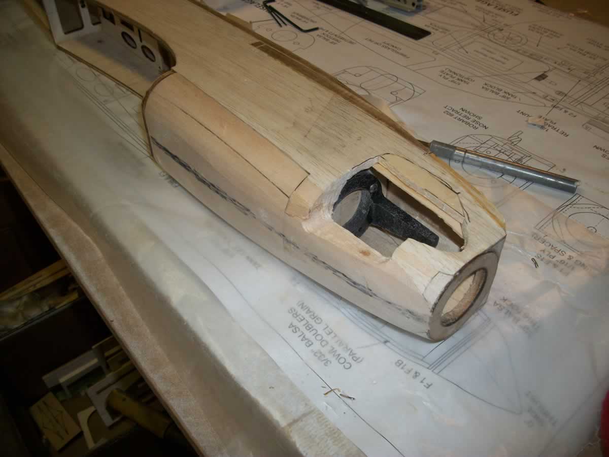
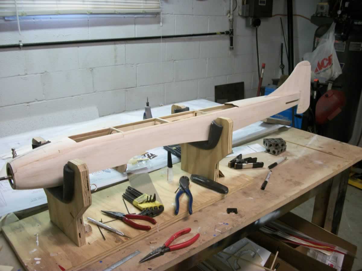
I took advantage of some time off work and did a little work on the DB40. As can be seen in the pics, I'm building this one with a side mount engine that will sport a Mac's header and pipe exhaust system. I built a Sportster 40 ~80ish that had a built up cowl similar to this construction and was trying to remember what I did back then to make this easier, ha! I'm sure there's an easier way to do this but here's what I'm doing.
I installed the engine mount to check for clearance and glued in the cowl chin tri-stock then proceeded to butcher the sidewall.
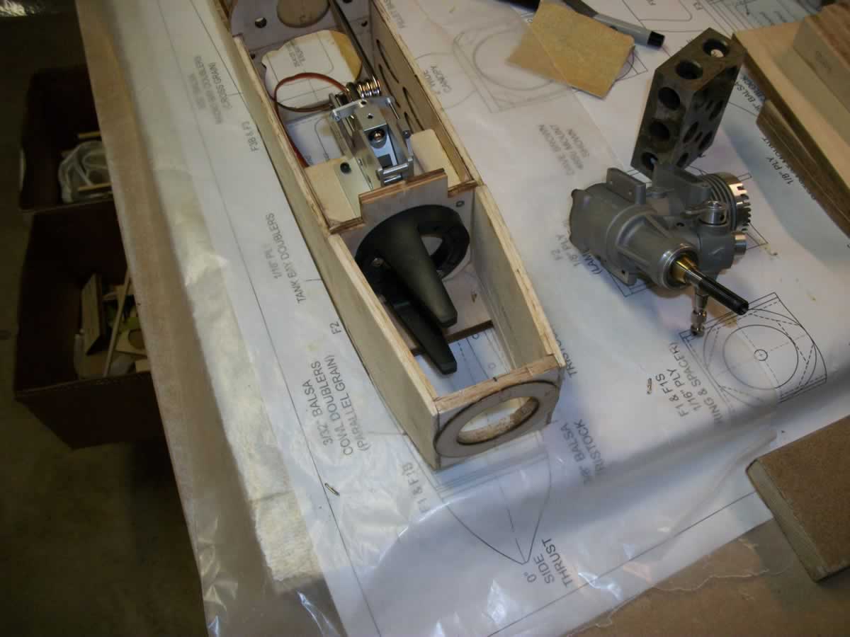

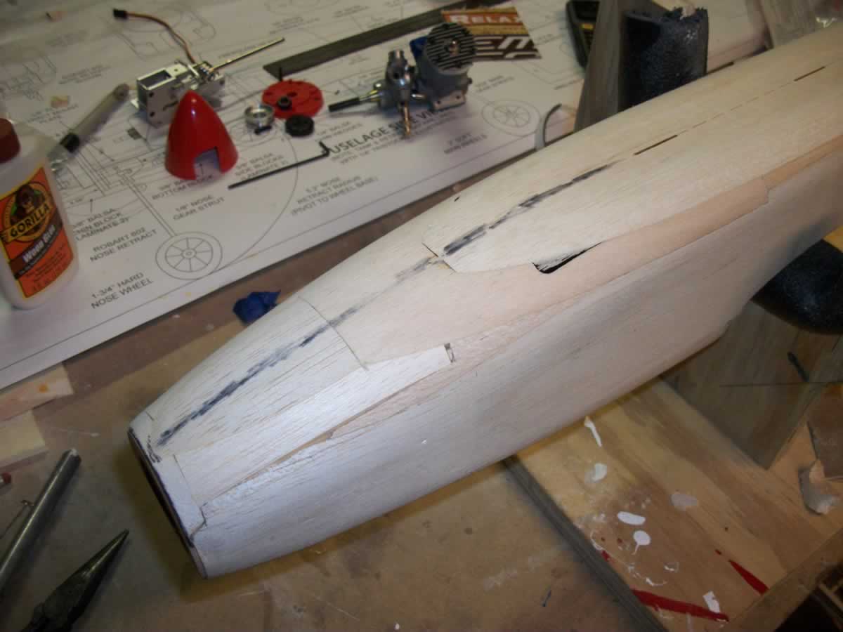
The engine sitting in place and some preliminary whittling on the cowl after temporarily gluing the upper and lower balsa blocks in place.
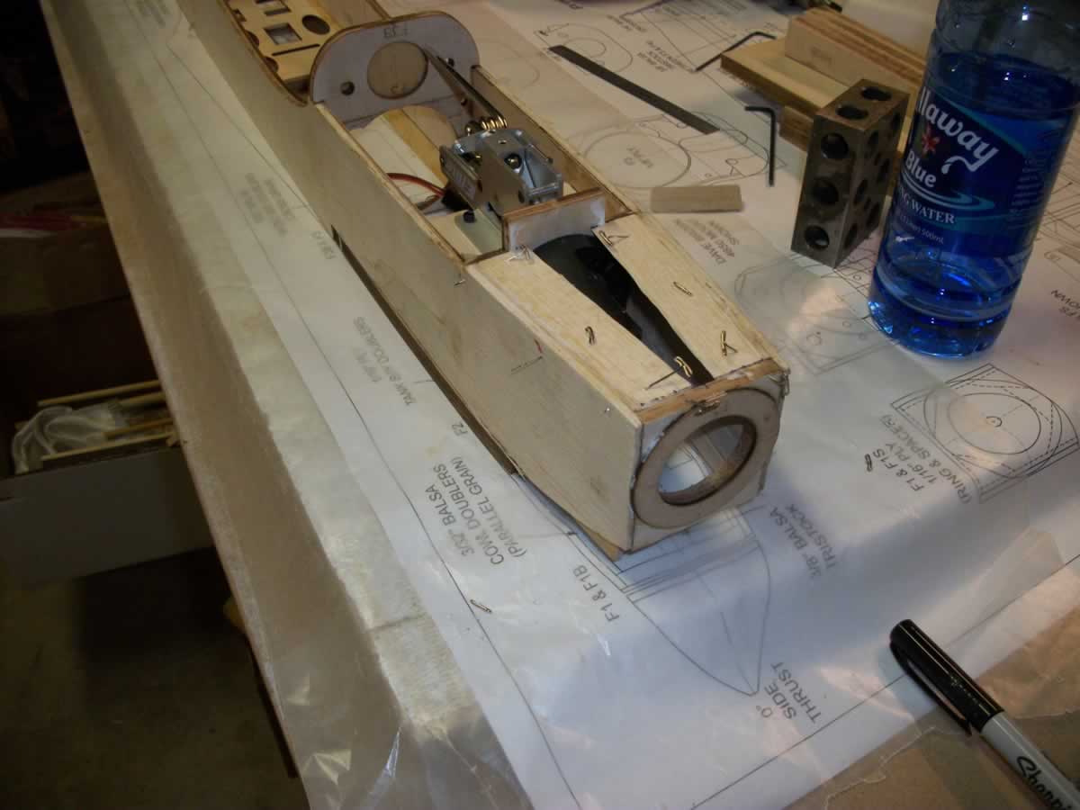
I got everything roughed in but somehow went a little overboard on the sanding, easy fix though.

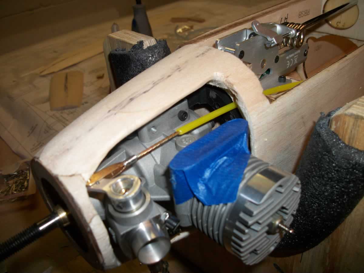
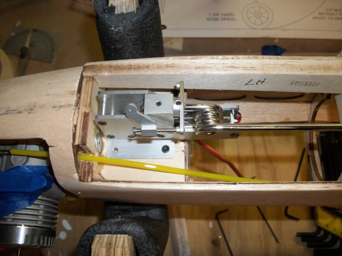
With the gear and retract in place I ran the throttle cable and did some more pondering on the steering linkage.
I took advantage of some time off work and did a little work on the DB40. As can be seen in the pics, I'm building this one with a side mount engine that will sport a Mac's header and pipe exhaust system. I built a Sportster 40 ~80ish that had a built up cowl similar to this construction and was trying to remember what I did back then to make this easier, ha! I'm sure there's an easier way to do this but here's what I'm doing.
I installed the engine mount to check for clearance and glued in the cowl chin tri-stock then proceeded to butcher the sidewall.
The engine sitting in place and some preliminary whittling on the cowl after temporarily gluing the upper and lower balsa blocks in place.
I got everything roughed in but somehow went a little overboard on the sanding, easy fix though.
With the gear and retract in place I ran the throttle cable and did some more pondering on the steering linkage.
12-31-2013 | 01:42 PM
#14
Thread Starter
Member
Joined: Nov 2012
Posts: 68
Likes: 0
Received 0 Likes
on
0 Posts
From: Center Point, AL
Hi David
It's a big hole there I agree, I'll rebuild it once the header is in place like you said. Progress is easy when your on vacation and the weather sucks!
It's a big hole there I agree, I'll rebuild it once the header is in place like you said. Progress is easy when your on vacation and the weather sucks!
12-31-2013 | 09:13 PM
#16
Thread Starter
Member
Joined: Nov 2012
Posts: 68
Likes: 0
Received 0 Likes
on
0 Posts
From: Center Point, AL
David
Happy New Year to you and all our fellow R/C flyers as well.
The nose gear strut diameter is 4mm. I haven't been able to operate the gear yet, but the quality looks good and strong. Hopefully the electronics will hold up a reasonable amount of flights. I've built roughly eight airplanes, but this is my first pattern plane or retract installation and I'm thoroughly enjoying the quality of the wood and clean cuts.
Here's to a prosperous new year, Cheers!
Dave
01-18-2014 | 03:23 PM
#17
Thread Starter
Member
Joined: Nov 2012
Posts: 68
Likes: 0
Received 0 Likes
on
0 Posts
From: Center Point, AL
Hey all,
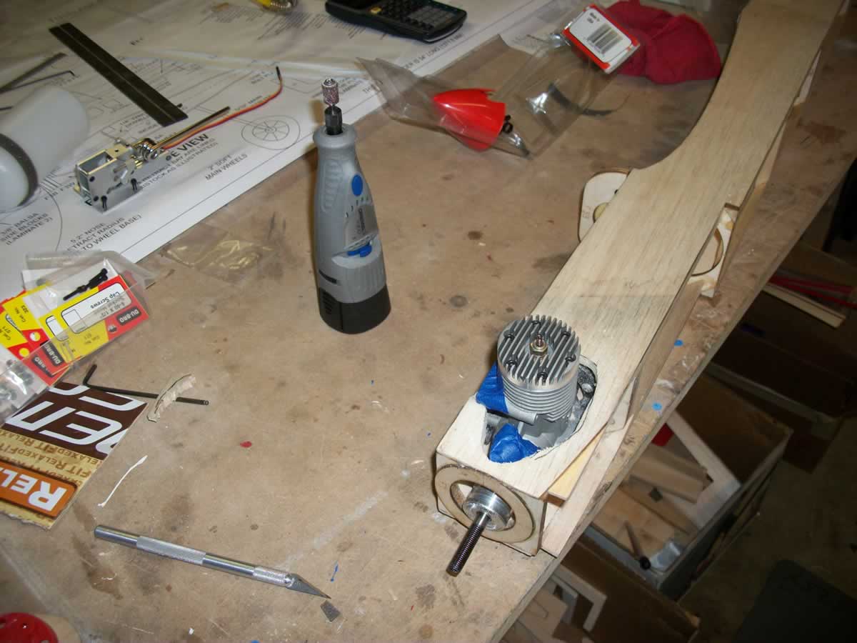
Found some time to work on the DB40 and got to thinking about isolating the the E-Fight retracts. I found isolators (grommets) on the net with a 5/32" ID 3/16" tall with a 3/32" groove for a 1/4" hole.
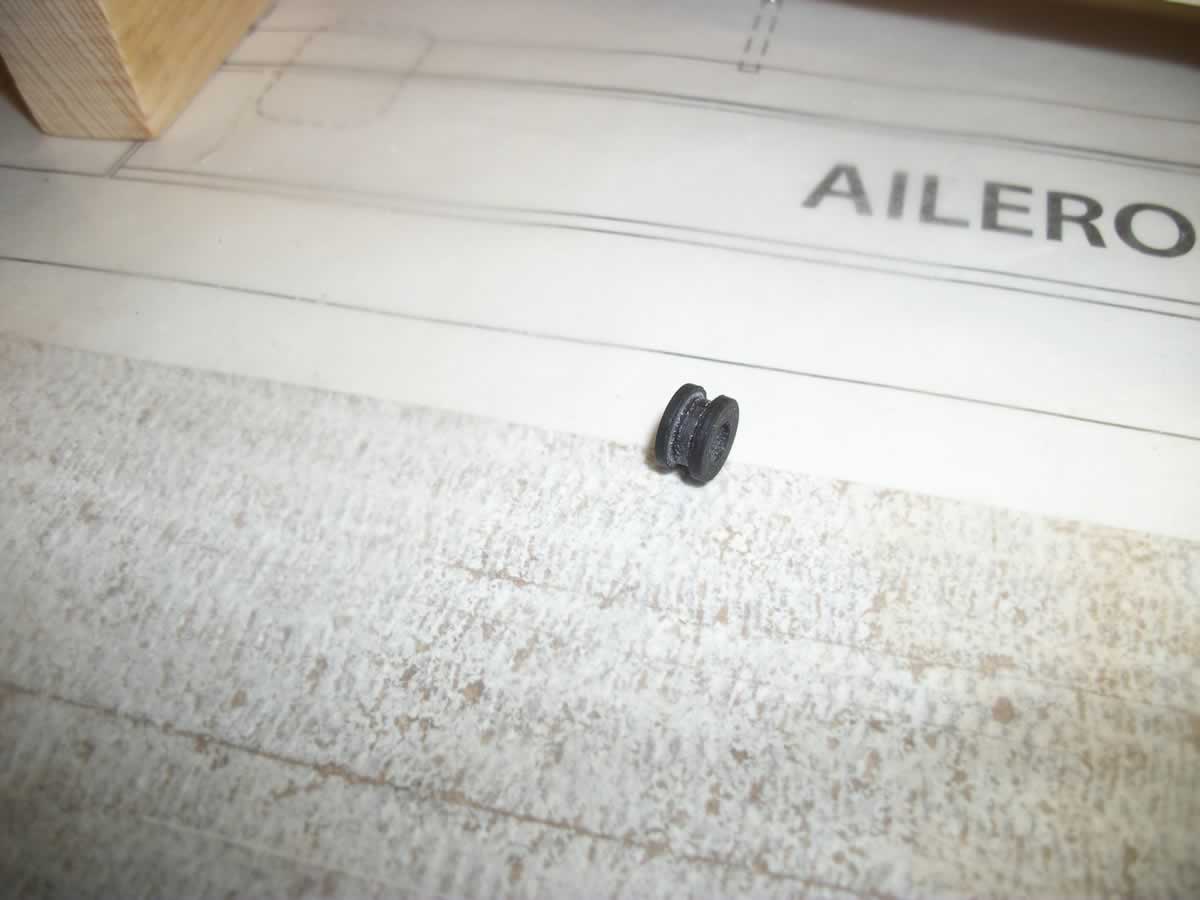
I just happened to have some 1/8" ID brass tube with a 5/32" OD so I clamped a cutter in the vise and while spinning the tube in the drill chuck I cut spacers to 3/16" long. The only bad thing is I had to open the holes in the retracts to 1/4"
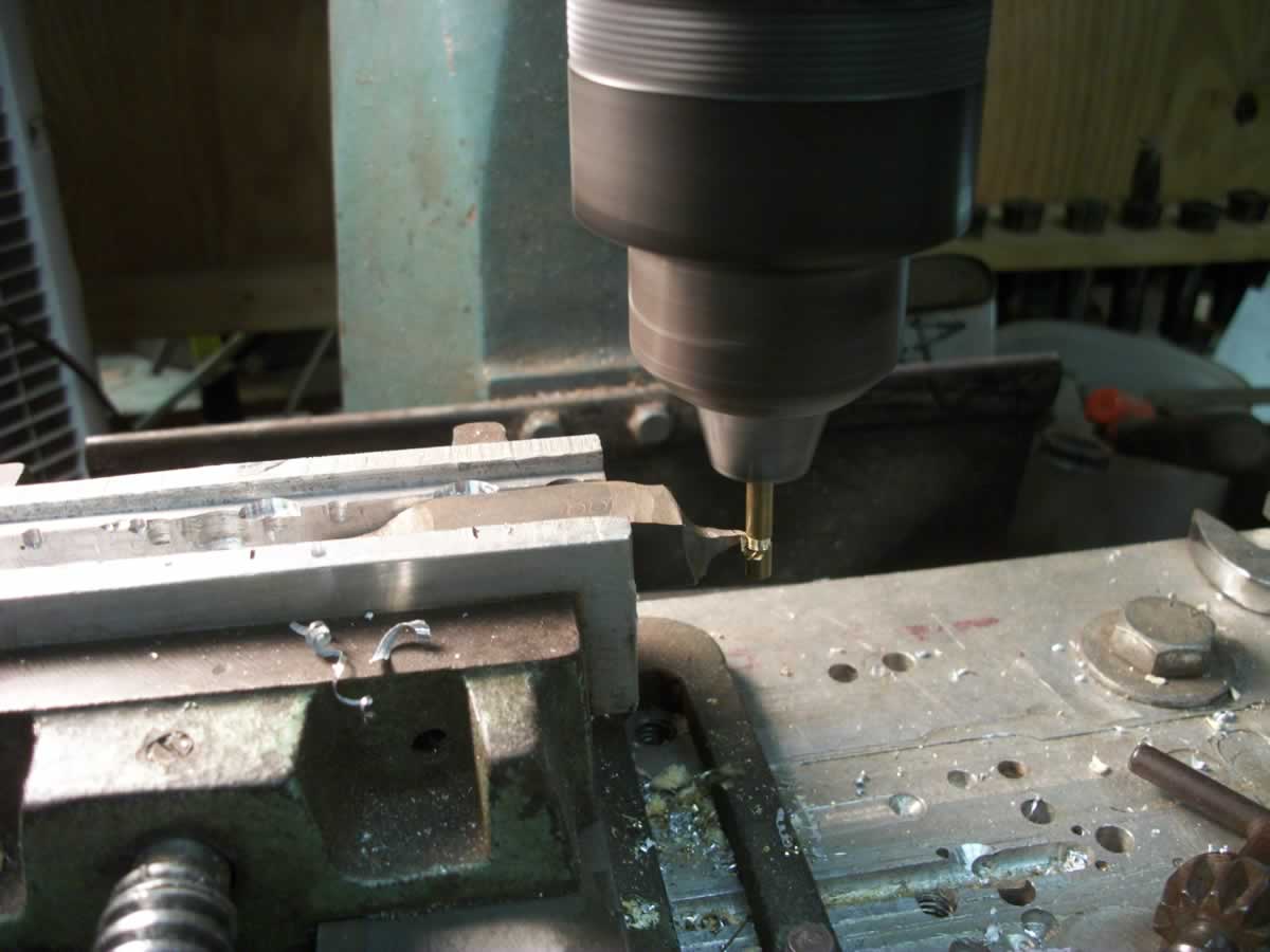
I hope that I can get some life out of these retracts by making this modification and plan on mounting the mains the same.
Oh, and I started on the right wing panel. I found some 1/4" carbon rods (also on the net) and made a wing jig out them and 1x2 board. So far they look good and straight.
Cheers!
Found some time to work on the DB40 and got to thinking about isolating the the E-Fight retracts. I found isolators (grommets) on the net with a 5/32" ID 3/16" tall with a 3/32" groove for a 1/4" hole.
I just happened to have some 1/8" ID brass tube with a 5/32" OD so I clamped a cutter in the vise and while spinning the tube in the drill chuck I cut spacers to 3/16" long. The only bad thing is I had to open the holes in the retracts to 1/4"
I hope that I can get some life out of these retracts by making this modification and plan on mounting the mains the same.
Oh, and I started on the right wing panel. I found some 1/4" carbon rods (also on the net) and made a wing jig out them and 1x2 board. So far they look good and straight.
Cheers!
01-19-2014 | 10:39 AM
#18
My Feedback: (3)
Dave,
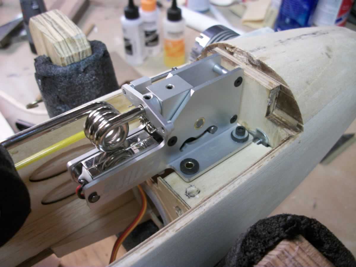
nice job on the NG mounting. I shaped the side blocks to contour and then hollowed them out on the inside except for the contact point area with the formers. It just gives more space to work on the NG installation/removable and steering mechanism.
David
nice job on the NG mounting. I shaped the side blocks to contour and then hollowed them out on the inside except for the contact point area with the formers. It just gives more space to work on the NG installation/removable and steering mechanism.
David
01-20-2014 | 05:42 AM
#19
Thread Starter
Member
Joined: Nov 2012
Posts: 68
Likes: 0
Received 0 Likes
on
0 Posts
From: Center Point, AL
Thanks David
I need to solder a washer onto the brass spacers to keep them from pressing into the ply. When I drilled the holes I wasn't thinking ahead far enough by drilling it from the backside just deep enough for the blind nut, then clearance the rest of the way through. I won't make the same mistake before I glue the mount blocks into the wings. The right wing panel came out of the jig with a slight bow of <1mm tip to root at the spar. I'm not sure if I should worry about that, but I may try and get it out anyway before I start on the left panel. Thoughts on that anyone?
Dave
04-11-2014 | 01:58 PM
#20
My Feedback: (3)
Hey Dave,
I am doing another run of kits this month and was wondering if you had made any progress on your build. Your thread is the only kit build reference at the moment so I'm referring others to it.
Thanks again for taking the time to post your build.
Cheers, David
I am doing another run of kits this month and was wondering if you had made any progress on your build. Your thread is the only kit build reference at the moment so I'm referring others to it.
Thanks again for taking the time to post your build.
Cheers, David
04-14-2014 | 09:46 AM
#21
Thread Starter
Member
Joined: Nov 2012
Posts: 68
Likes: 0
Received 0 Likes
on
0 Posts
From: Center Point, AL
Hey David
I've mounted the main gear and now working on the aileron servo mounting, I will take a few shots and post them later. I ordered the 3040(?) aileron servos back in November and they just arrived last week. So it's been in mostly just starring at wings figuring out the best way to mount aileron servos. Do you have any images of how you mounted them?
So anyway, now it's spring and outdoor projects are calling for my attention and it may be a little minute before I get back on it.
Dave
04-14-2014 | 11:55 AM
#22
My Feedback: (3)
Hey David
I've mounted the main gear and now working on the aileron servo mounting, I will take a few shots and post them later. I ordered the 3040(?) aileron servos back in November and they just arrived last week. So it's been in mostly just starring at wings figuring out the best way to mount aileron servos. Do you have any images of how you mounted them?
So anyway, now it's spring and outdoor projects are calling for my attention and it may be a little minute before I get back on it.
Dave
I've mounted the main gear and now working on the aileron servo mounting, I will take a few shots and post them later. I ordered the 3040(?) aileron servos back in November and they just arrived last week. So it's been in mostly just starring at wings figuring out the best way to mount aileron servos. Do you have any images of how you mounted them?
So anyway, now it's spring and outdoor projects are calling for my attention and it may be a little minute before I get back on it.
Dave
good to hear that you've been making progress. I look forward to the picture updates.
Yea, the suggested servos, the Spektrum A5030's, are very popular and great mini servo's. In fact, they seemed to be unavailable anywhere for the entire time you mention. They were sold out for good reason, they have excellent specs and perform well. I'm glad they finally came in as it means that Spektrum must have produced a new batch and hopefully they will be widely available again. Spektrum has also been expanding their line of servos with HV versions of the existing ones and a few new ones. There is now an A5060 as well which is an impressive mini servo (albeit at 3 times the retail price), which can put out 118 oz in of torque when powered on 2s lipo's. Transit time is still 0.11 sec/60 degrees. These servos are excellent candidates for even rudders on 60-120 size classics. I'll probably try one on the rudder of my next 60 size build.
Another pretty good servo in the mini class, at least on paper, is the Tactic TSX25. It is also a mini servo slightly larger and heavier than the A5030 but it produces a great deal of torque, north of 90 oz in, at 6V. They are a tad slower than the Spektrum's but still pretty fast compared to many others in the mini category. I have purchased 5 of them to try out in a 50 or 60 size classic. I'll have further info once I receive them and check them out. By the way, these servos are all coreless, dual ball bearing digital servos.
Just quickly you mentioned 3040's which are also a Spektrum servo but they are micro metal gear servos. Any of the 3000 series servos (4 of them) would be well suited for carburetor controls, retract valves and steering of nose gears but don't use them on control surfaces of 40 size models. I wouldn't use them on the controls of 25 size models either (the 4000 series are there for that). They can be used on controls of foamy's and maybe 10-15 size classic glow models with narrow controls. I'd consider using them on ailerons of such a model but would still go with 4000's on the tail.
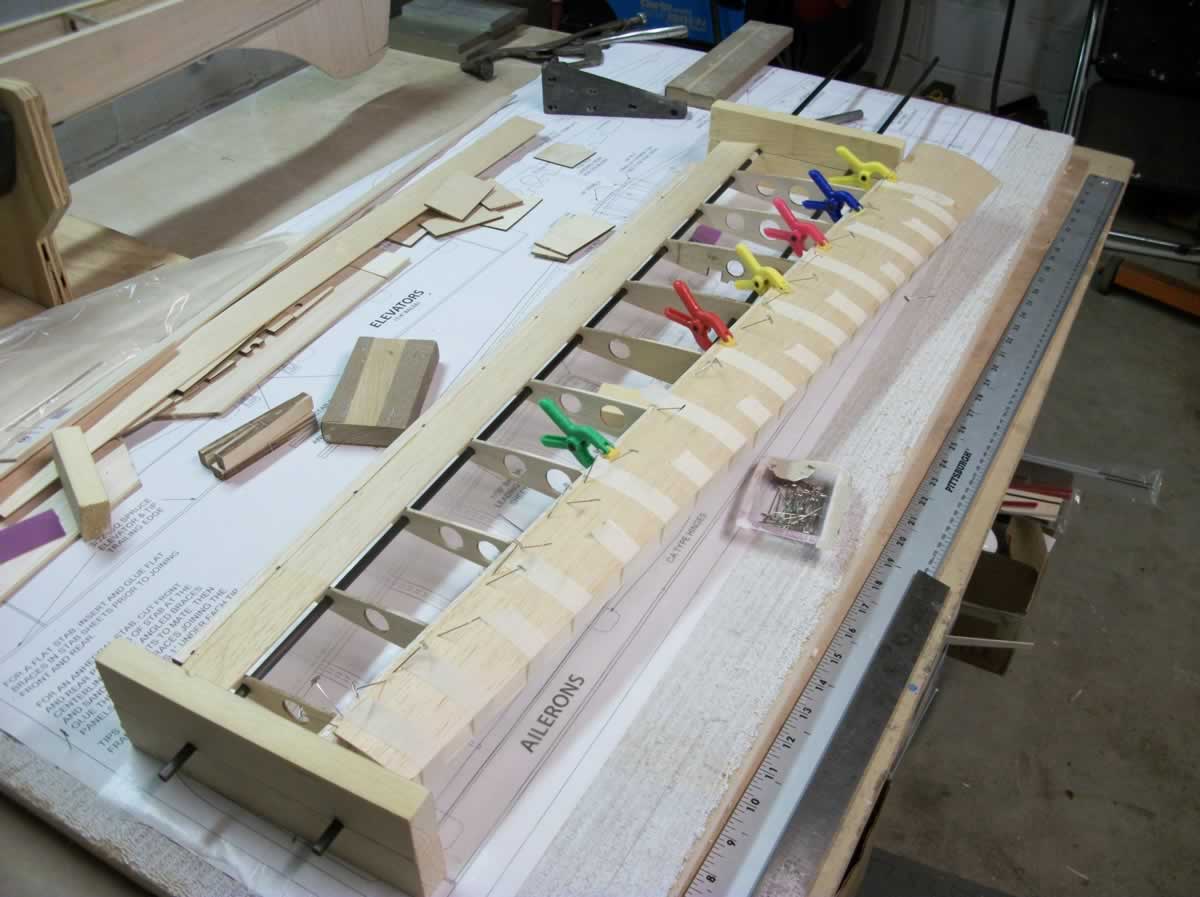
Speaking of ailerons, there are basically two ways I do individual aileron servo installations - either the servo is mounted upright with the servo wheel exposed on the surface of the wing bottom or the servo is side mounted so a servo arm protrudes through a hatch also mounted between rib bays on the underside. On the DB40 I suggested mounting the servos upright against the inside of rib R5. This puts the servo and control horn roughly at 1/3 of the aileron span and right beside a hinge - take a look at the plans for reference. What I usually do is cut a couple of lengths of 1/4" (or 3/8") square hardwood wide enough to span the servo width. The plans show rails that are 9/16" long. I then mark the rails for the servo holes to be drilled positioning the servo in the middle. Once mounted on the rails, I cut two rectangular pieces of 3/32" (or 1/8") balsa with their bases flush with the servo bottom. They are width sized to span the length of the servo and rail assembly and I generally cut them oversize height wise so the servo wheel needs to be removed when framing up the balsa box. With the two sides glued to the servo rails and level on a table top with the servo bottom, you can then cap the ends with more 3/32" balsa cut from the same length used for the sides. I keep the grain vertical so its easy to cut the sides. Finally, I usually also cap off the bottom of the pocket, primarily as it keeps the pocket square and gives it more strength. The entire pocket can be sanded smooth once glued up.
The servo pocket then gets glued up against a wing rib and against the spar shear web on the back of the spars (see plans). Unless the spar is square with the ribs (e.g., in a Kaos), you need to sand the front of the pocket at an angle so that it mates well against the shear web. In order to provide some material for sanding to an angle, I typically add another piece of 3/32" balsa to the front of the pocket or simply built up the front piece with 3/16" scrap - whatever scrap wood you have for these pockets does the trick.
Last but not least, I glue the pockets in so that the servo wheel is almost flush with the wing sheeting. Actually, placing it so the wheel is 1/8" higher than the rib works well. This allows for the 1/16" sheeting plus another 1/16" for the clevis attachment of the pushrod. The more concealed the servos the better. Mounting the servos laterally is more work and requires more material but is also a tad more elegant as it conceals the servo entirely leaving only the arm protruding from a slot in the 1/16" mounting plate. I tend to prefer the vertically mounted approach as it allows tthe servo to be installed/removed easily and doesn't require additional hardware and exposed screws to mount the plates to the wing. It really comes down to personal preference though. Both work equally well.
I have some pictures of the vertical mount somewhere but I can't seem to locate them. I might just take some others to post.
I hope this helps.
David
09-21-2014 | 06:51 AM
#24
My Feedback: (3)
Dave,
any updates on your build?
BTW, your Super Chipmunk avatar..., it has a great resemblance to the MK SC120 that I re-designed for e-power. It appears to have long aerobatic moments unlike most scaled down versions I have seen including the original MK version. Is that an ARF or a build from a kit (e.g., the Goldberg kit). Nice!
Cheers, David
Last edited by doxilia; 09-21-2014 at 06:54 AM.
09-22-2014 | 05:24 PM
#25
Thread Starter
Member
Joined: Nov 2012
Posts: 68
Likes: 0
Received 0 Likes
on
0 Posts
From: Center Point, AL
Hi David
I haven't made any progress lately because work has gotten in the way too often. Add summer activities and it's a recipe for idle builds. I will crank it back up when it gets to be lousy weather. Thanks for asking!
The Chipmunk is a Goldberg kit. It took a year to build it and I haven't flown it yet. The inverted Saito .90 is needing some help with idle so I'm installing a on-board glow system.
Dave
Last edited by soliex; 09-22-2014 at 05:27 PM.

