


Bj craft immortal

 05-19-2018 | 09:05 AM
#27

My Feedback: (3)
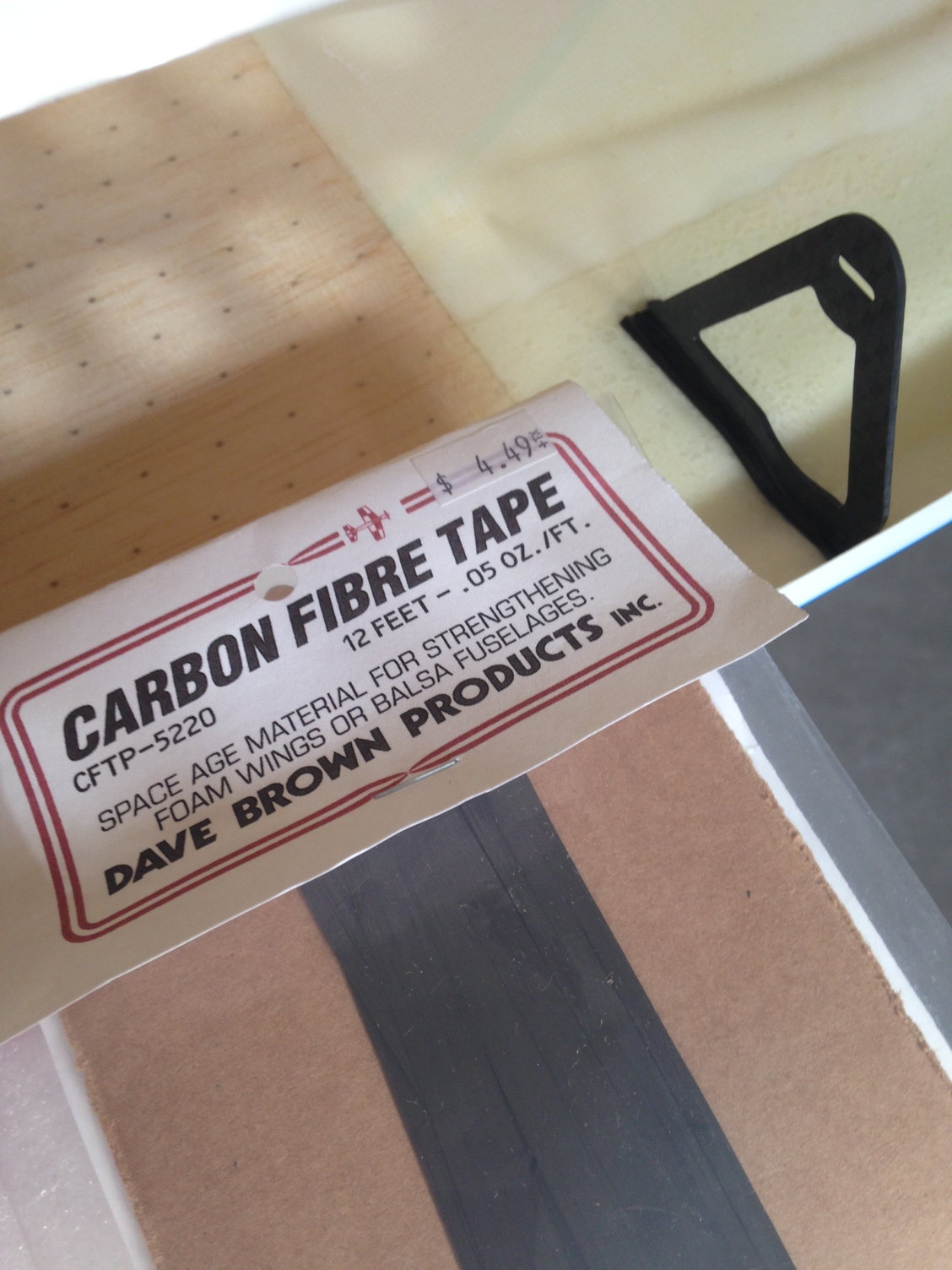
Would buying CF bonded plywood do the same thing for the rudder tray, just one step?
Carbon Fiber Poplar Plywood Core Sheets
or
Carbon Fiber Herex Foam Core Sheets
or
Carbon Fiber Balsa Plywood Core Sheets
I think these are from PT Model over in Europe
I too have an unopened package of Radio South CA hinges from back in the 80�s
They are still available ...
Pro-Hinges ? radiosouthrc.com
05-21-2018 | 11:47 AM
#28
Thread Starter
My Feedback: (1)
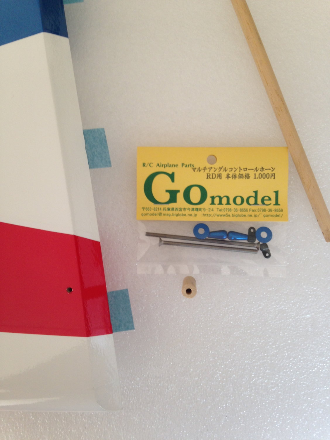
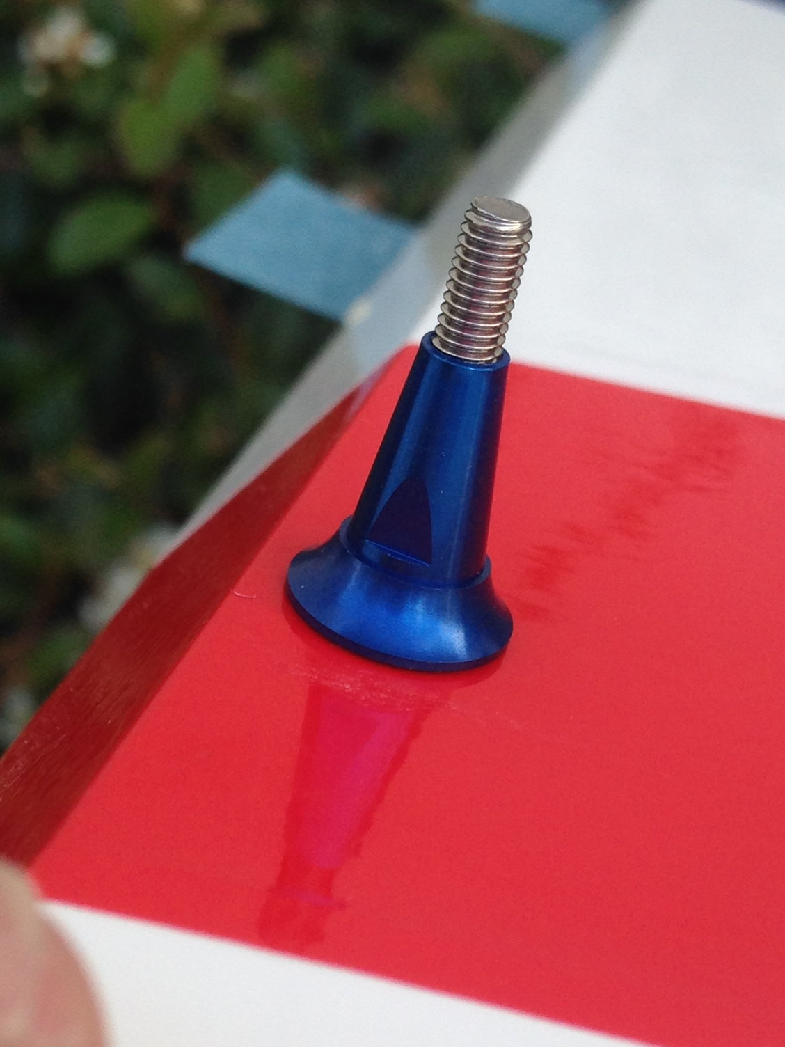
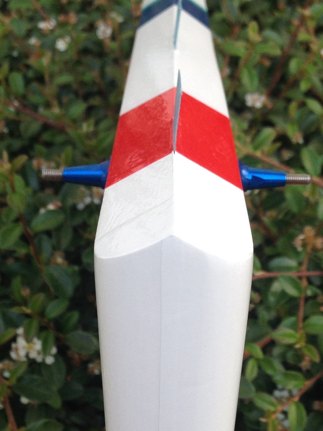
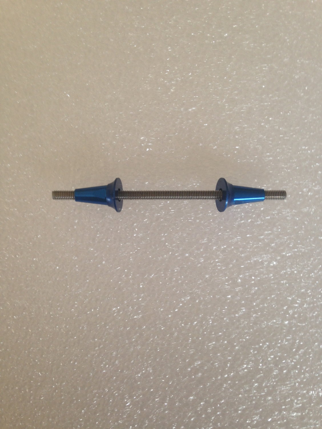
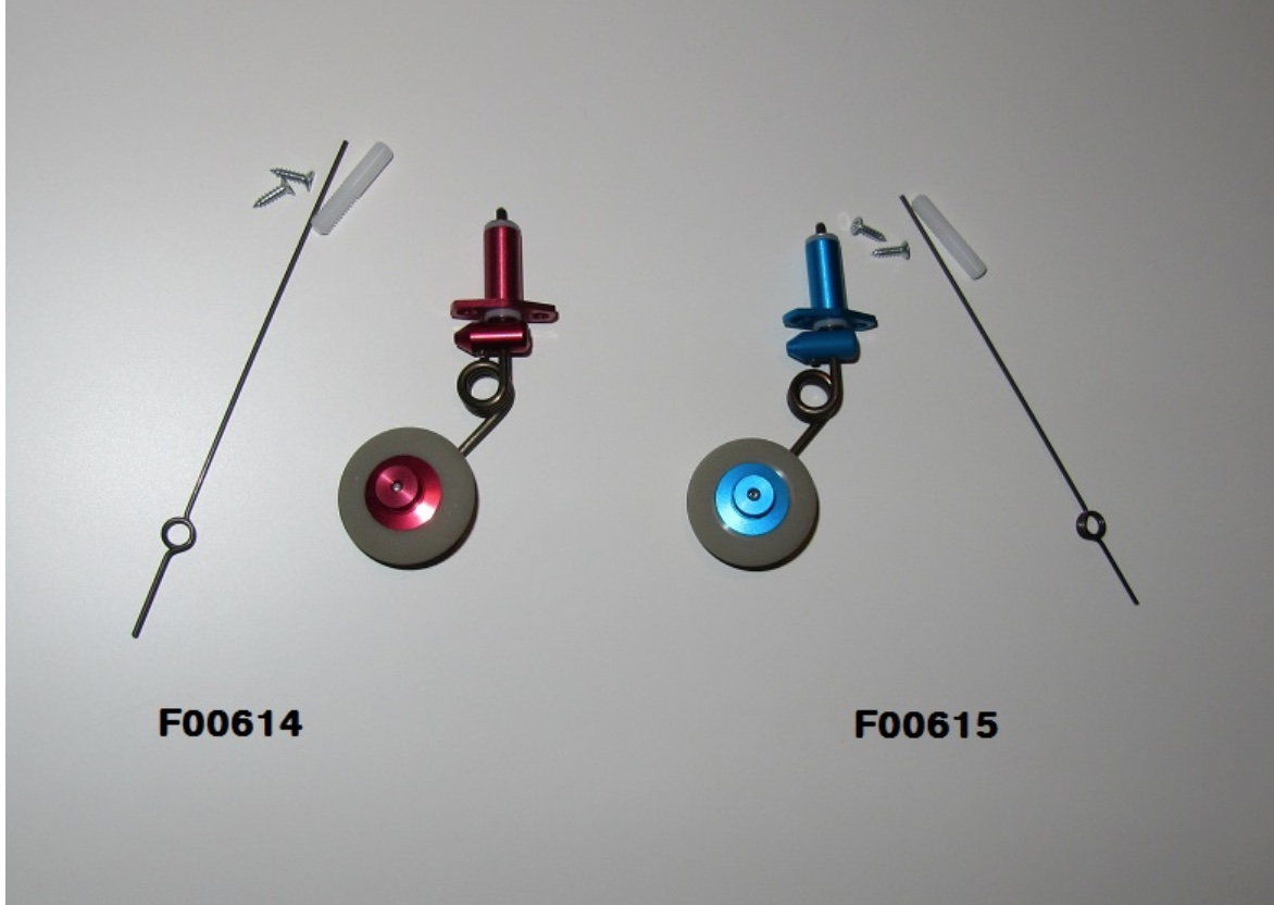
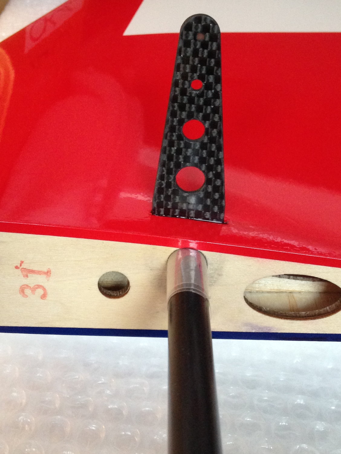
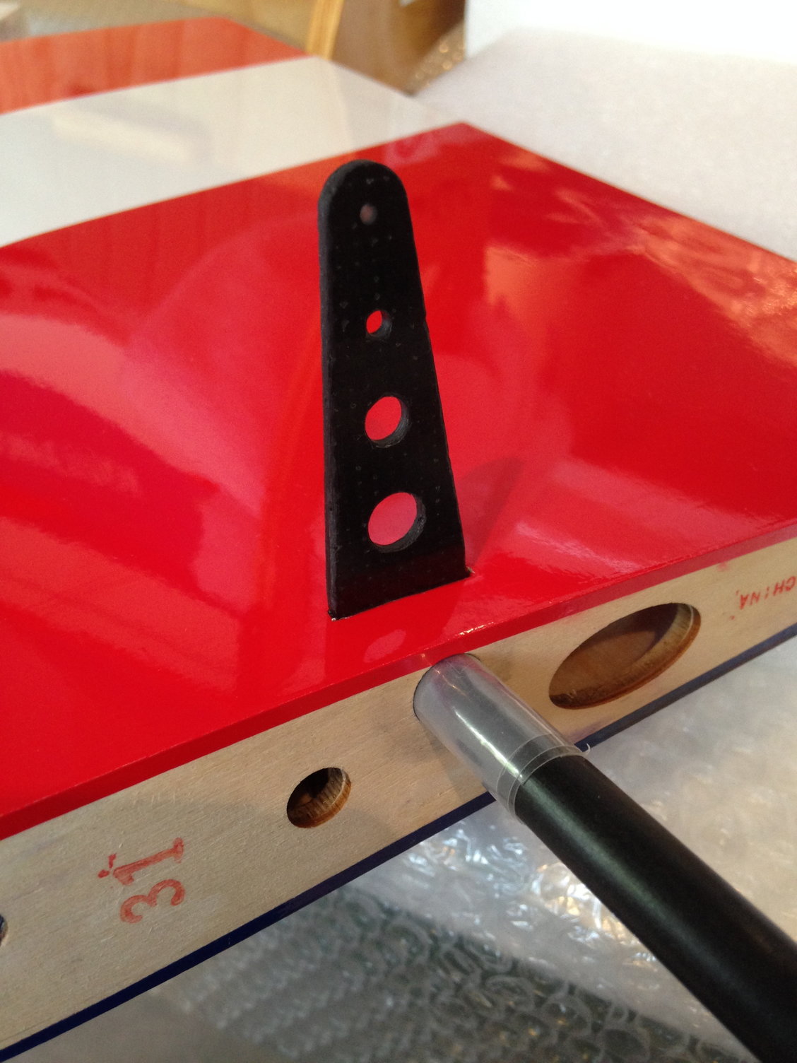
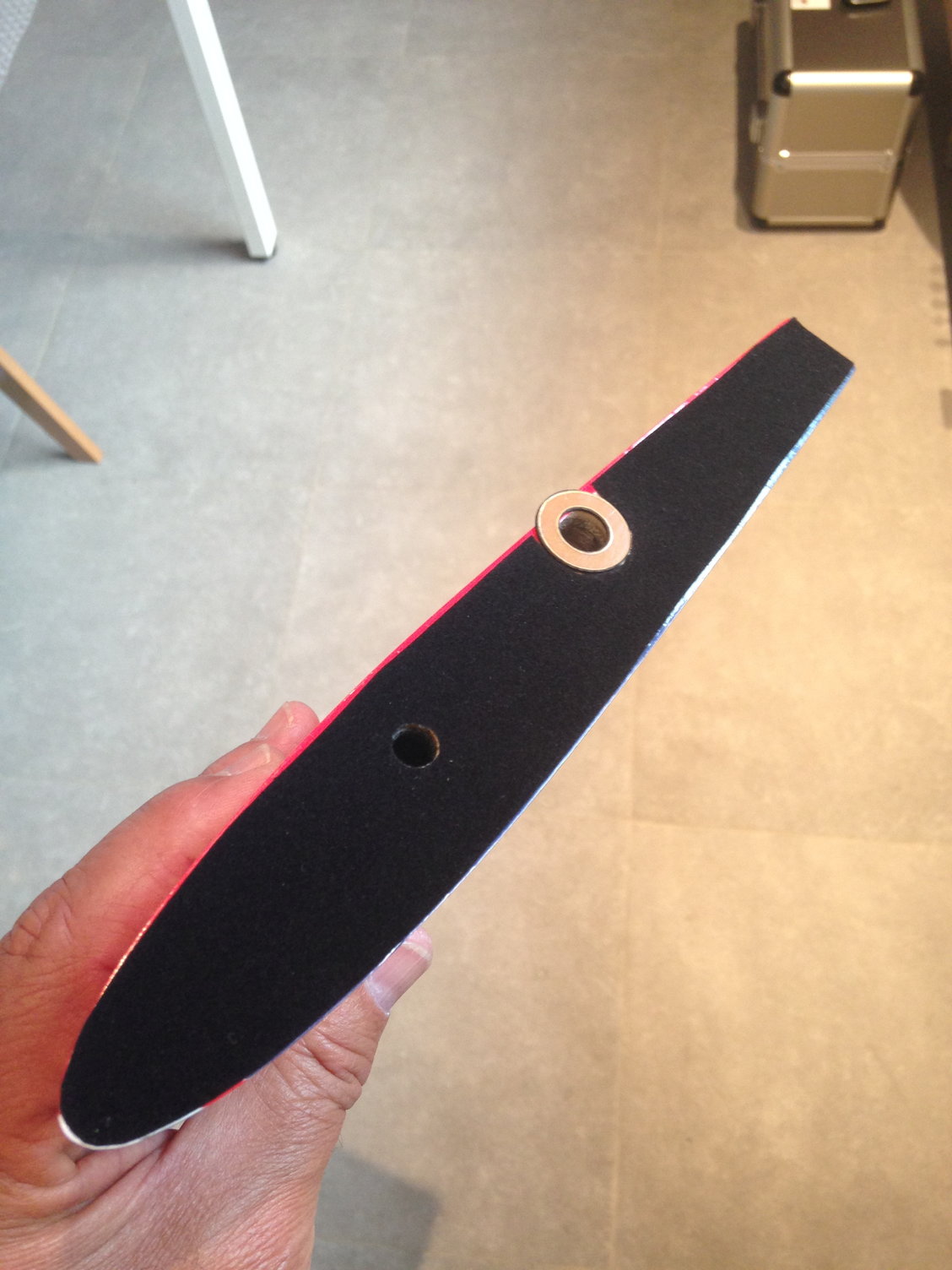
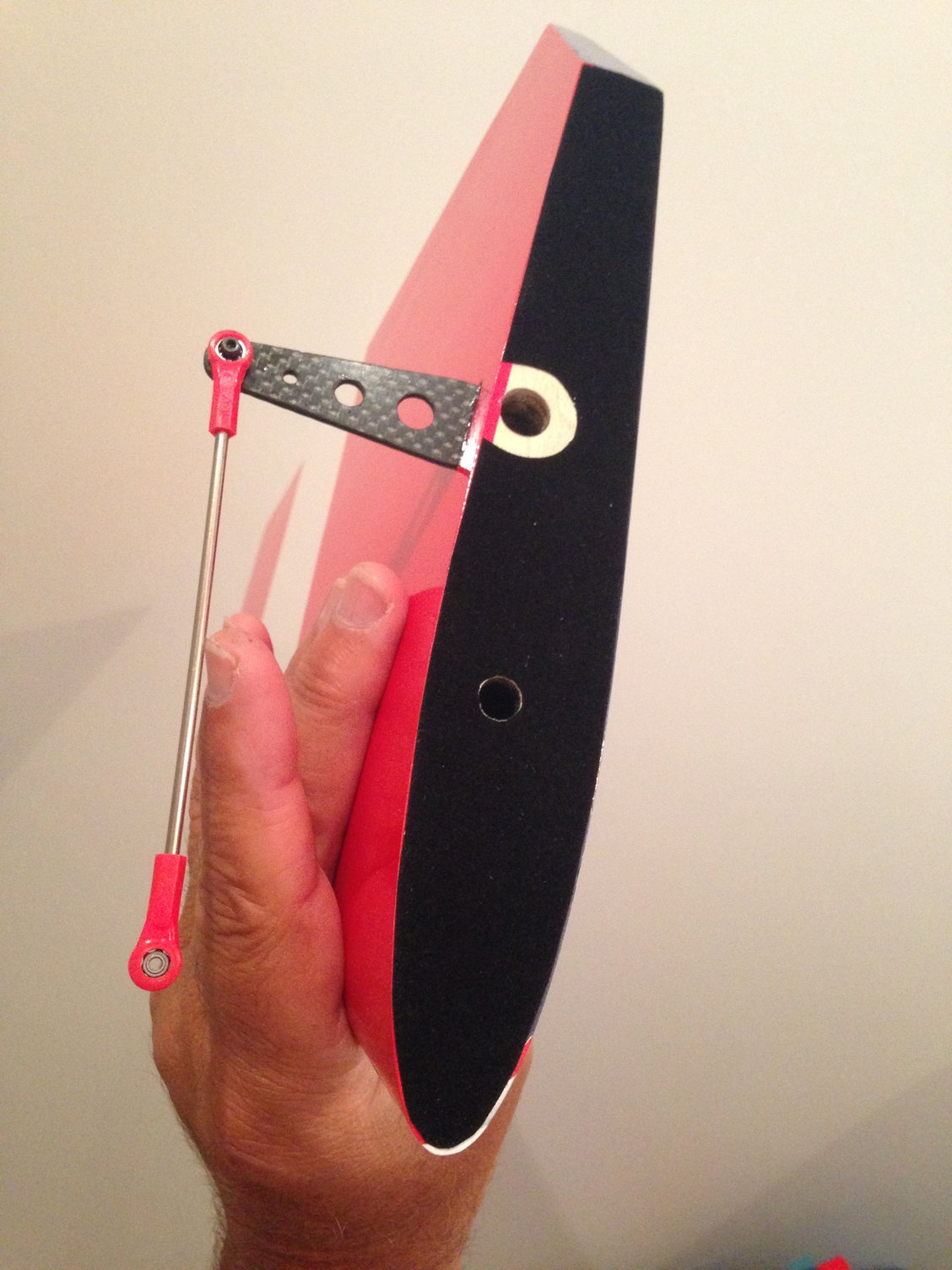
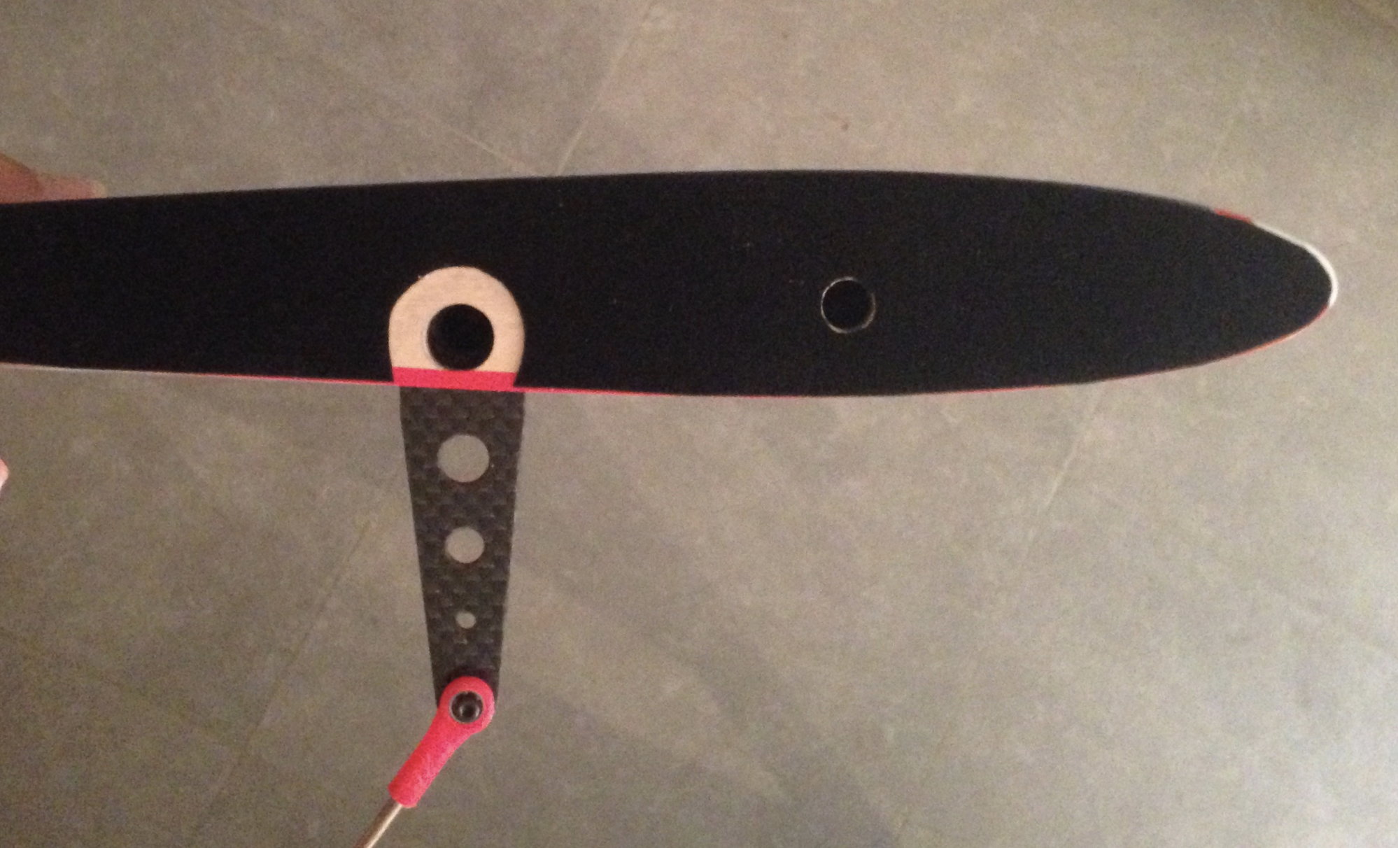
Instead of using the rudder horns coming with the kit, I have chosen to use a rudder GO MODEL set.
That's a nice set, you can secure with a small flat key
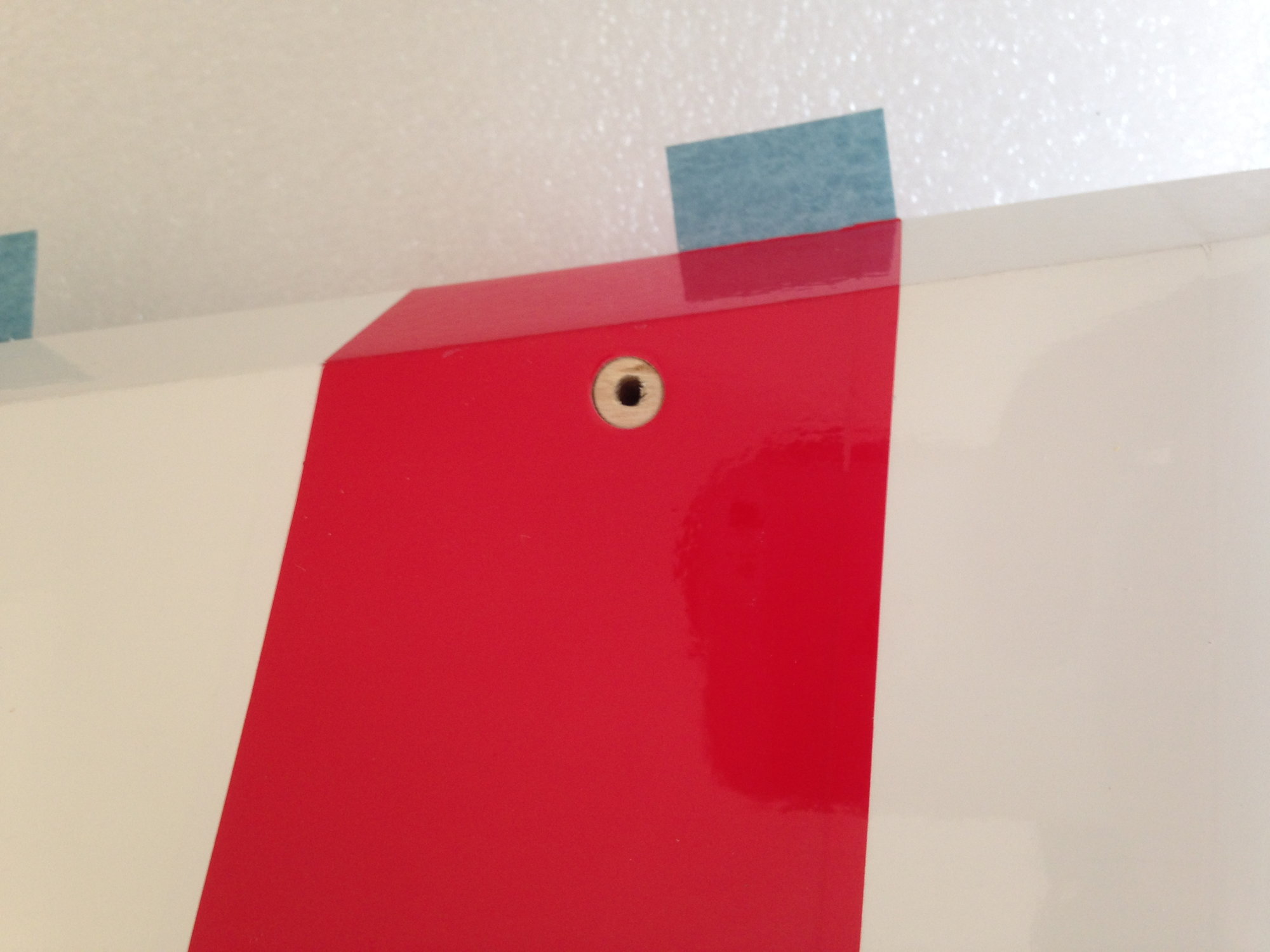
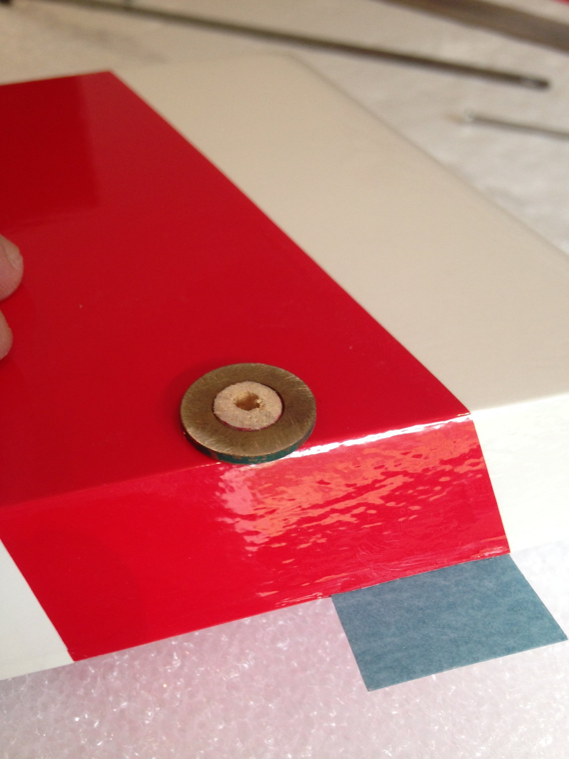
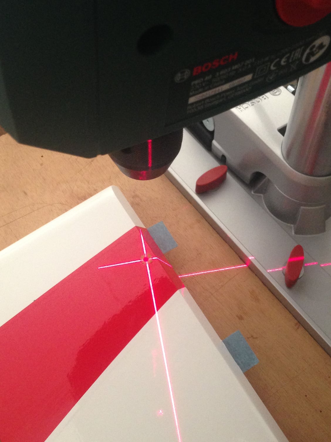
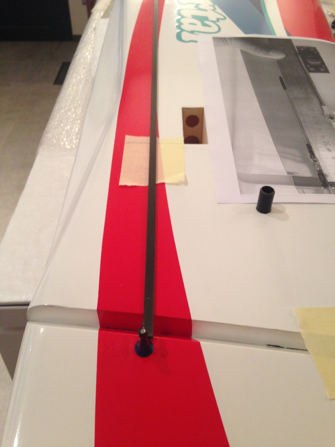
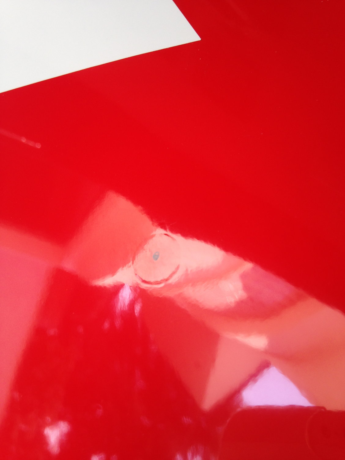
I drilled a 3mm hole in a 8 mm diameter hard wood dowel.
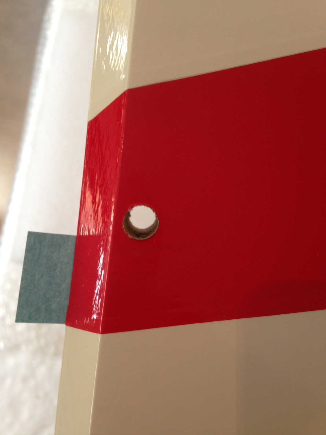
Then drilling the rudder with a 8mm bit need some attention. So I started with a 3mm hole, to be sure everything is square, went to 6 mm then 8 mm.
Before gluing the dowel with epoxy, I used a large washer to sand the dowel parallel and flush to the surface, without damaging the covering.

That's a nice set, you can secure with a small flat key
I drilled a 3mm hole in a 8 mm diameter hard wood dowel.
Then drilling the rudder with a 8mm bit need some attention. So I started with a 3mm hole, to be sure everything is square, went to 6 mm then 8 mm.
Before gluing the dowel with epoxy, I used a large washer to sand the dowel parallel and flush to the surface, without damaging the covering.
Last edited by J-P; 05-21-2018 at 12:07 PM.
05-21-2018 | 05:44 PM
#29

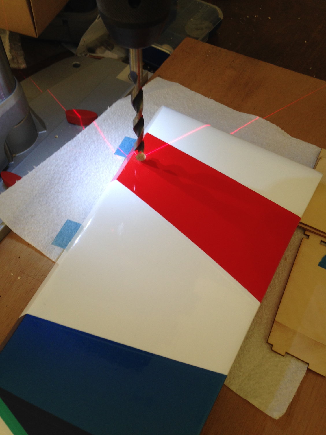
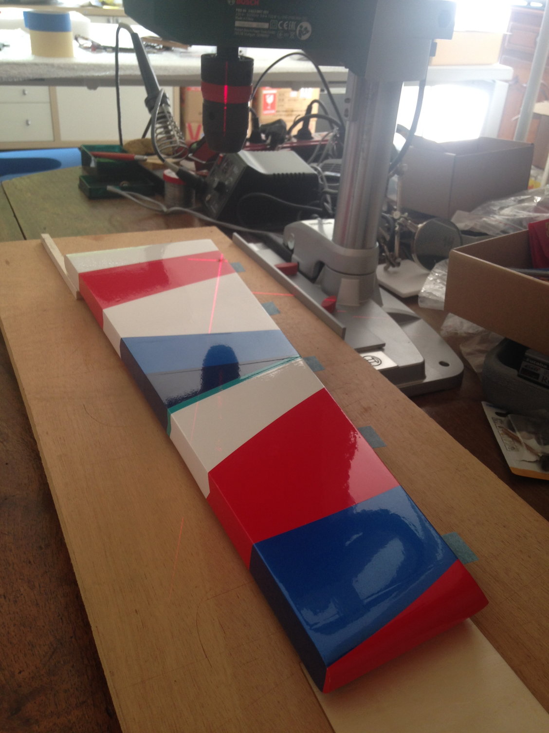
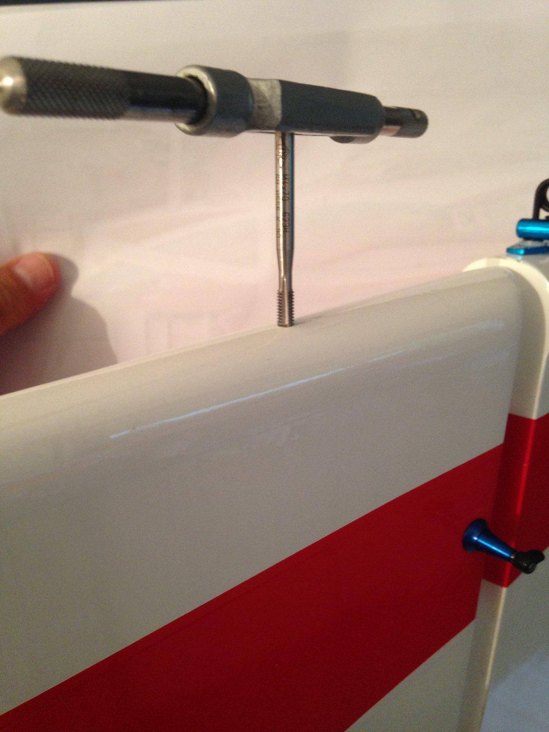
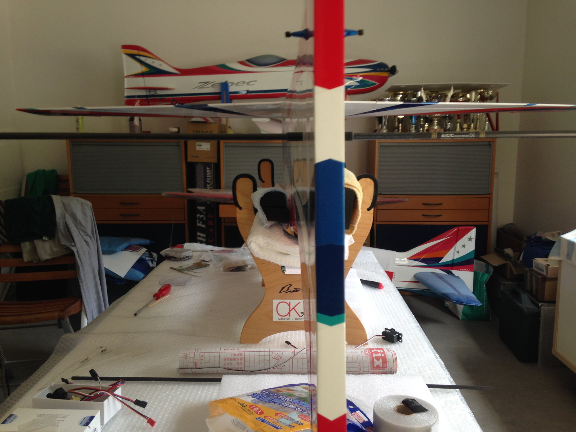
That laser trick looks great. Can you maybe describe a bit more how you set it up? Does that ensure that the hole is perpendicular to the rudder or just center the drill bit? Thanks.
05-22-2018 | 03:37 AM
#30
Thread Starter
My Feedback: (1)
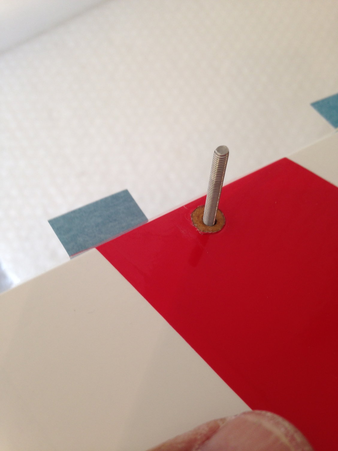
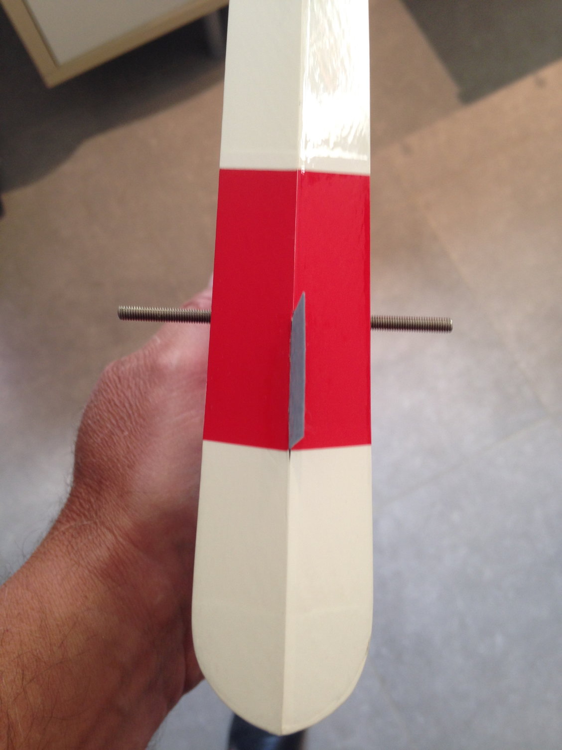
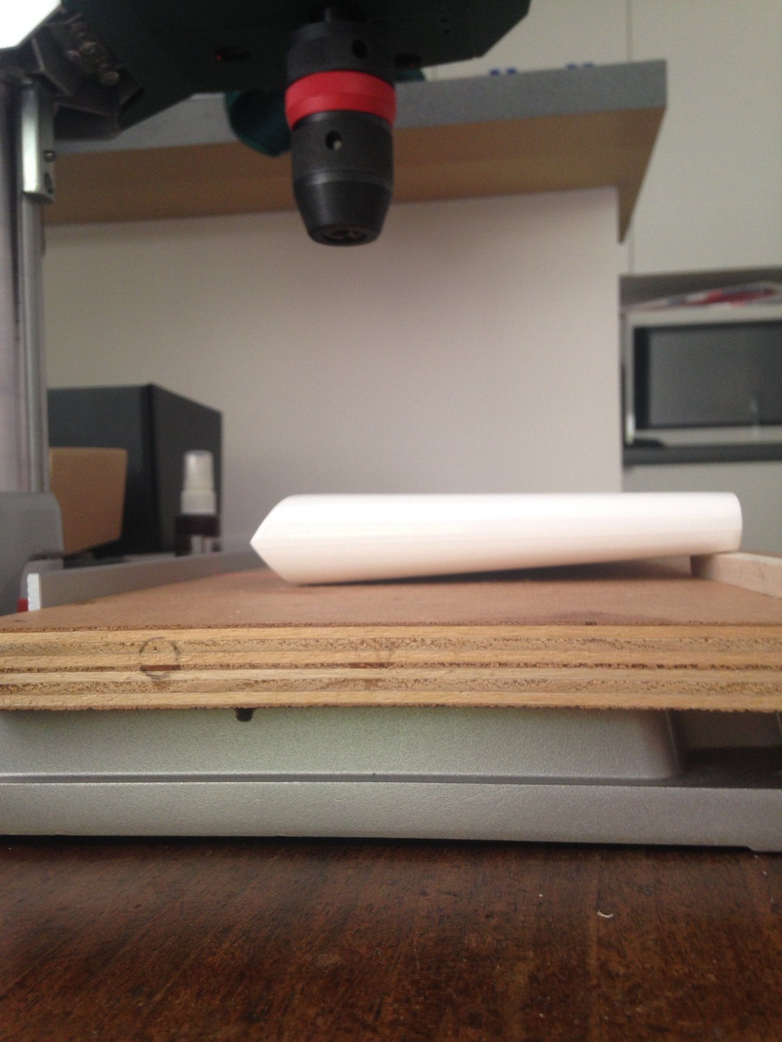
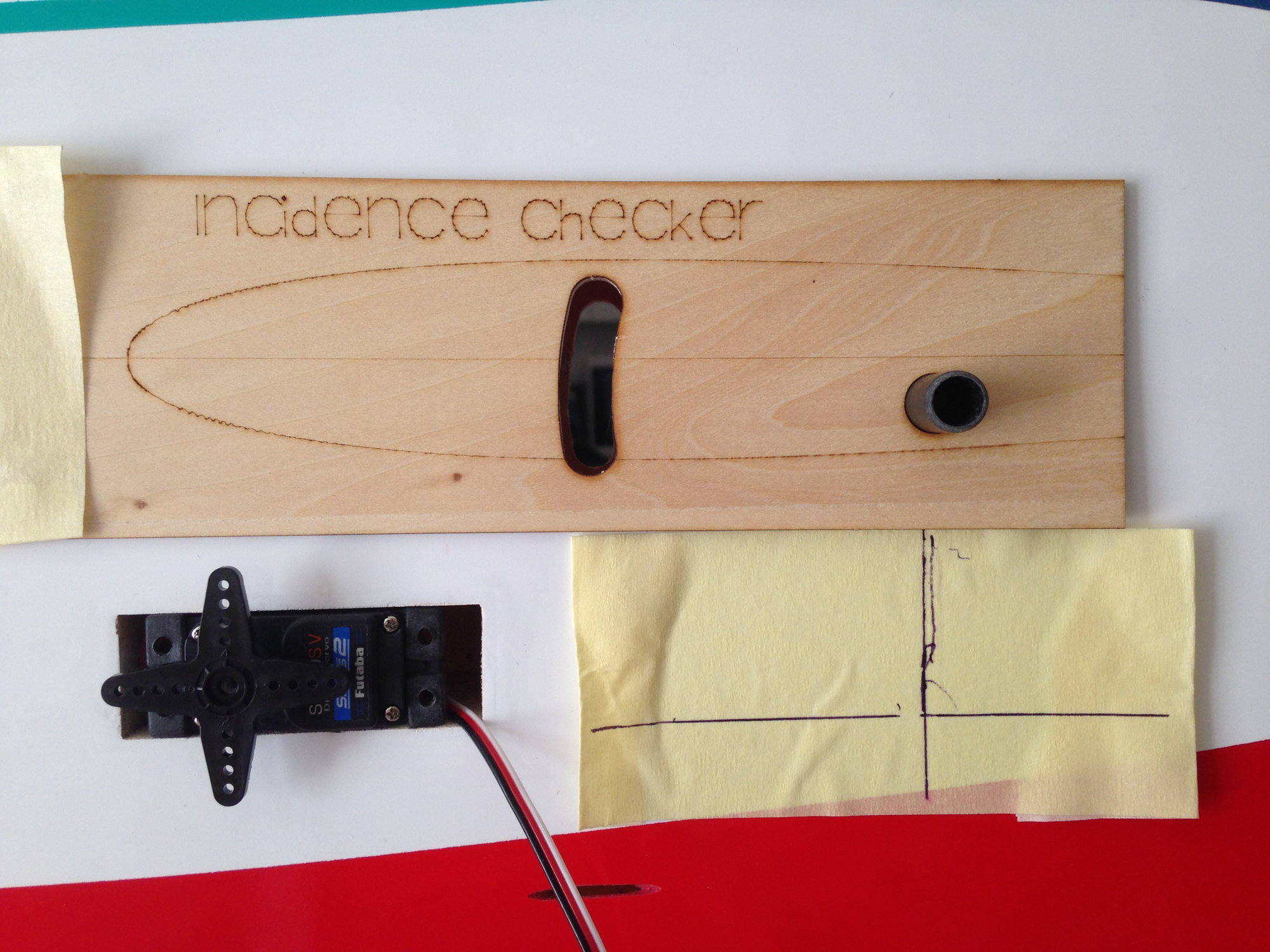
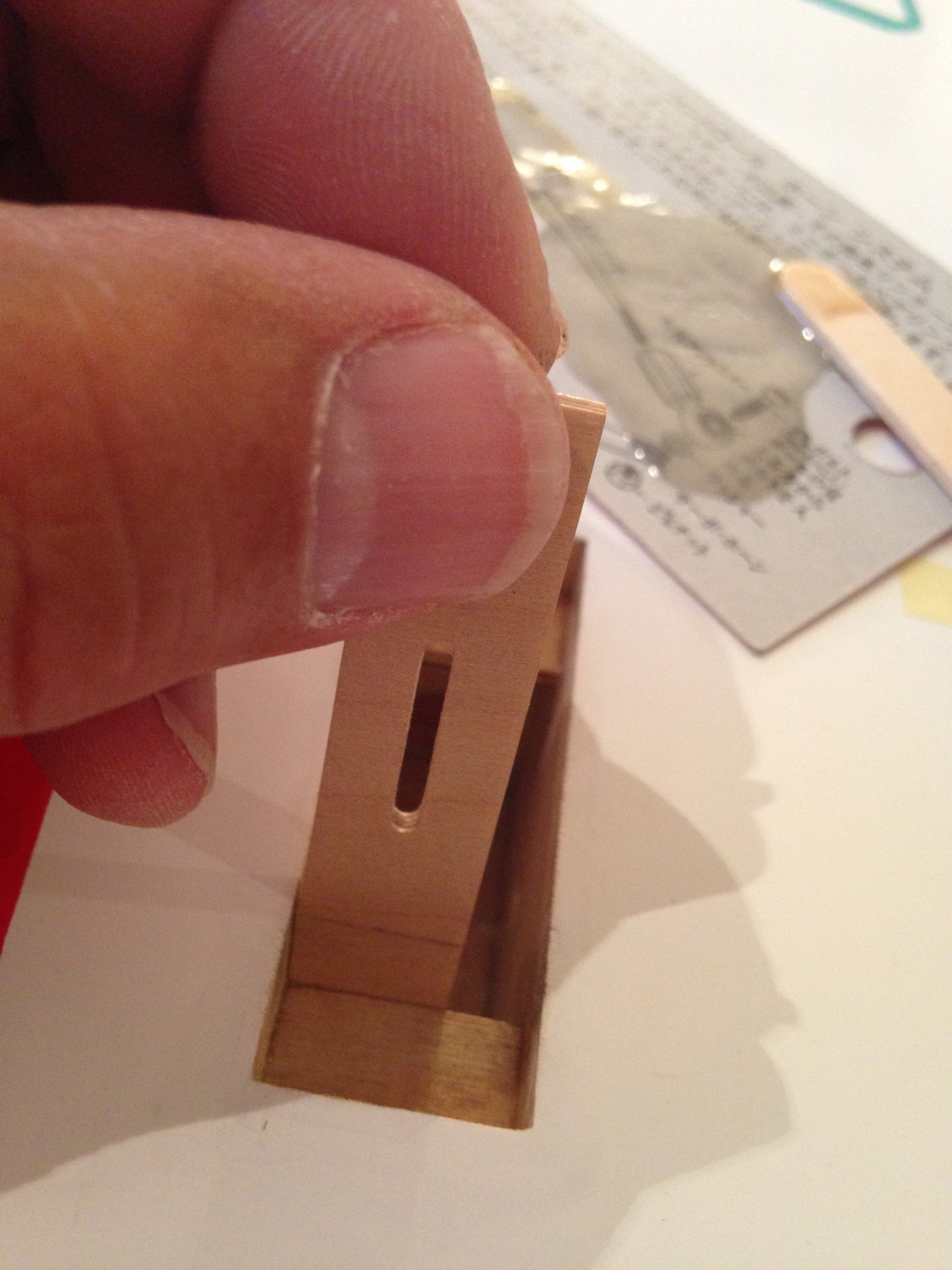
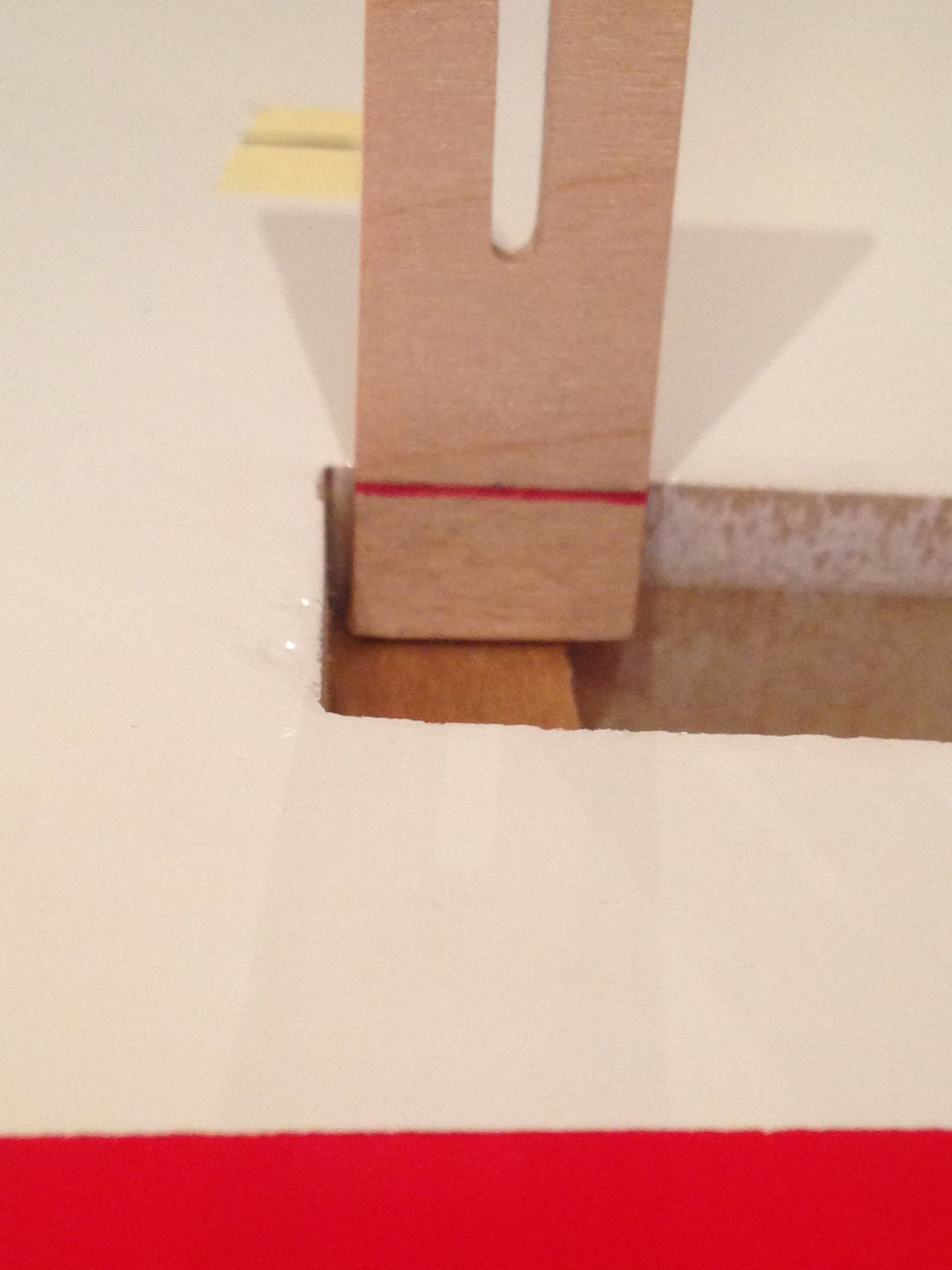
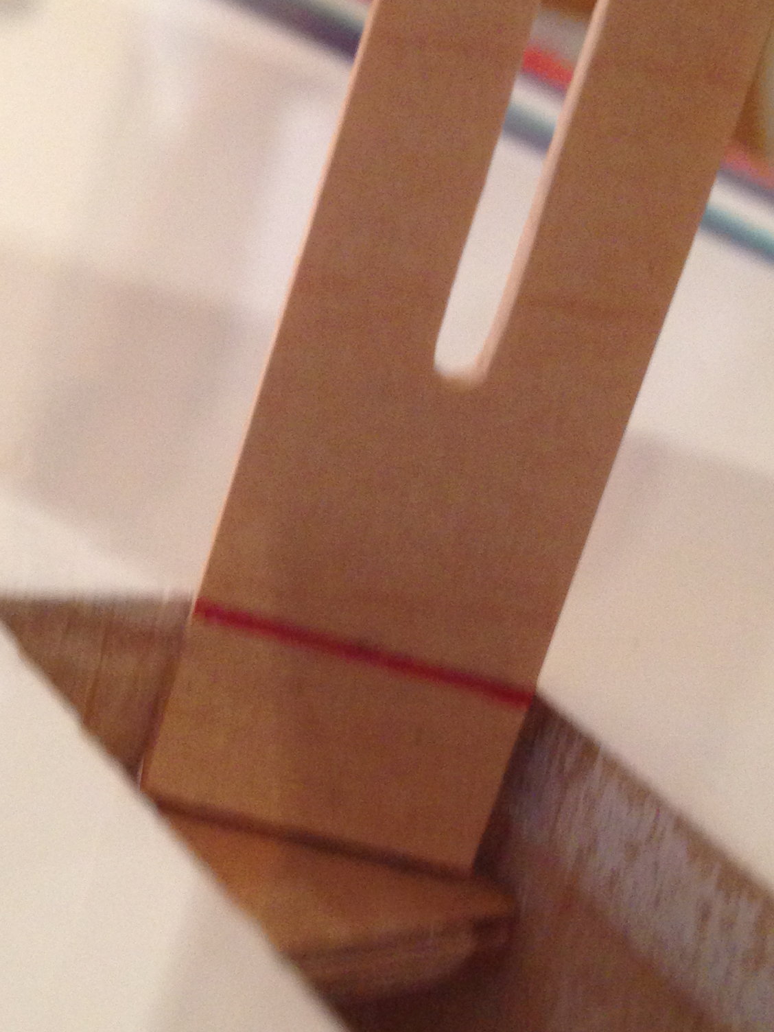
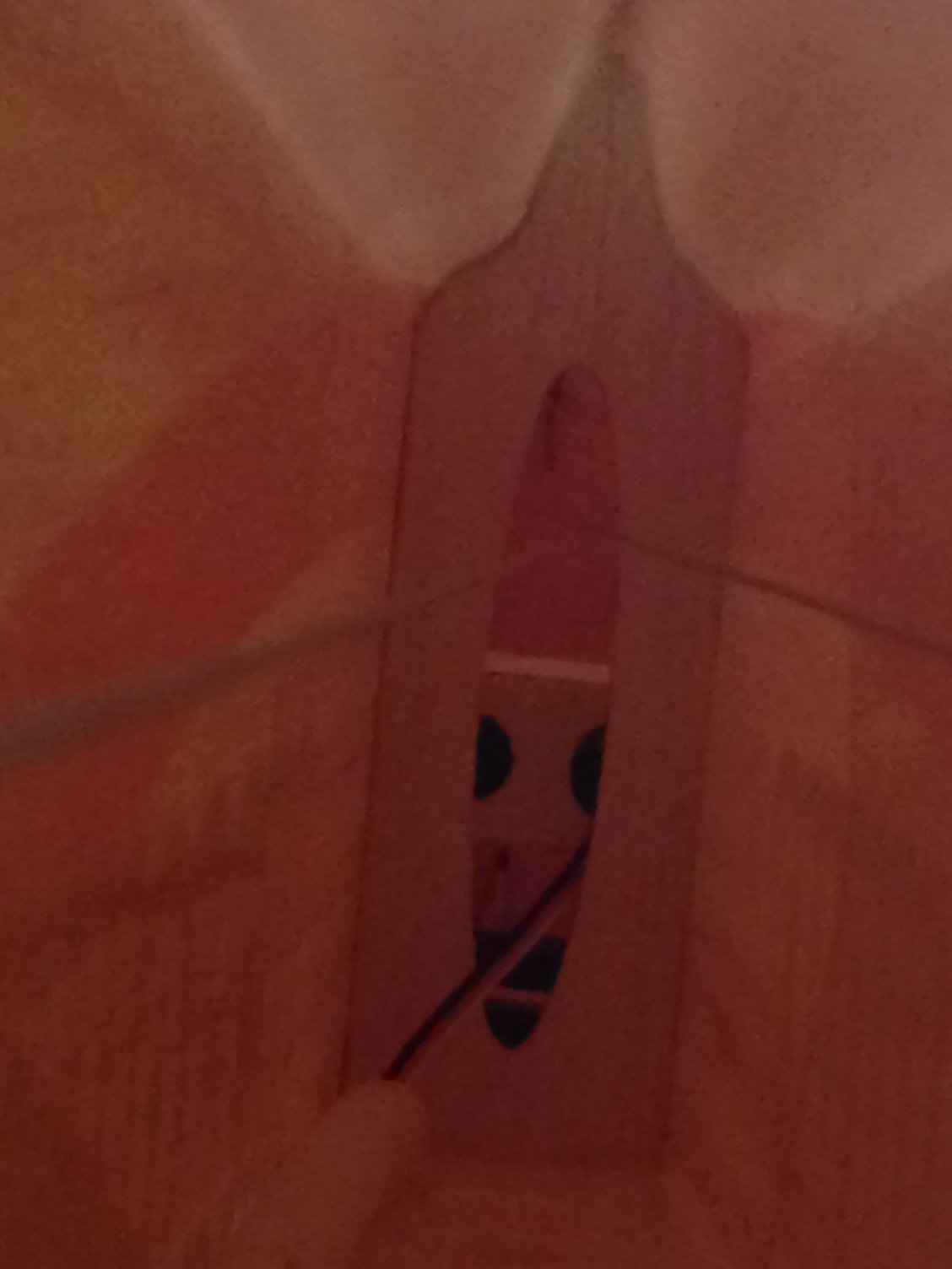
The laser is just helping centering the drill bit.
You have to position correctly the rudder to drill square.
The balsa used on the pic is not the correct one, the correction is 6 mm at the trailing edge, and 2mm at the rudder top.
You have to position correctly the rudder to drill square.
The balsa used on the pic is not the correct one, the correction is 6 mm at the trailing edge, and 2mm at the rudder top.
Last edited by J-P; 05-22-2018 at 03:42 AM.
05-22-2018 | 04:19 PM
#32
My Feedback: (3)
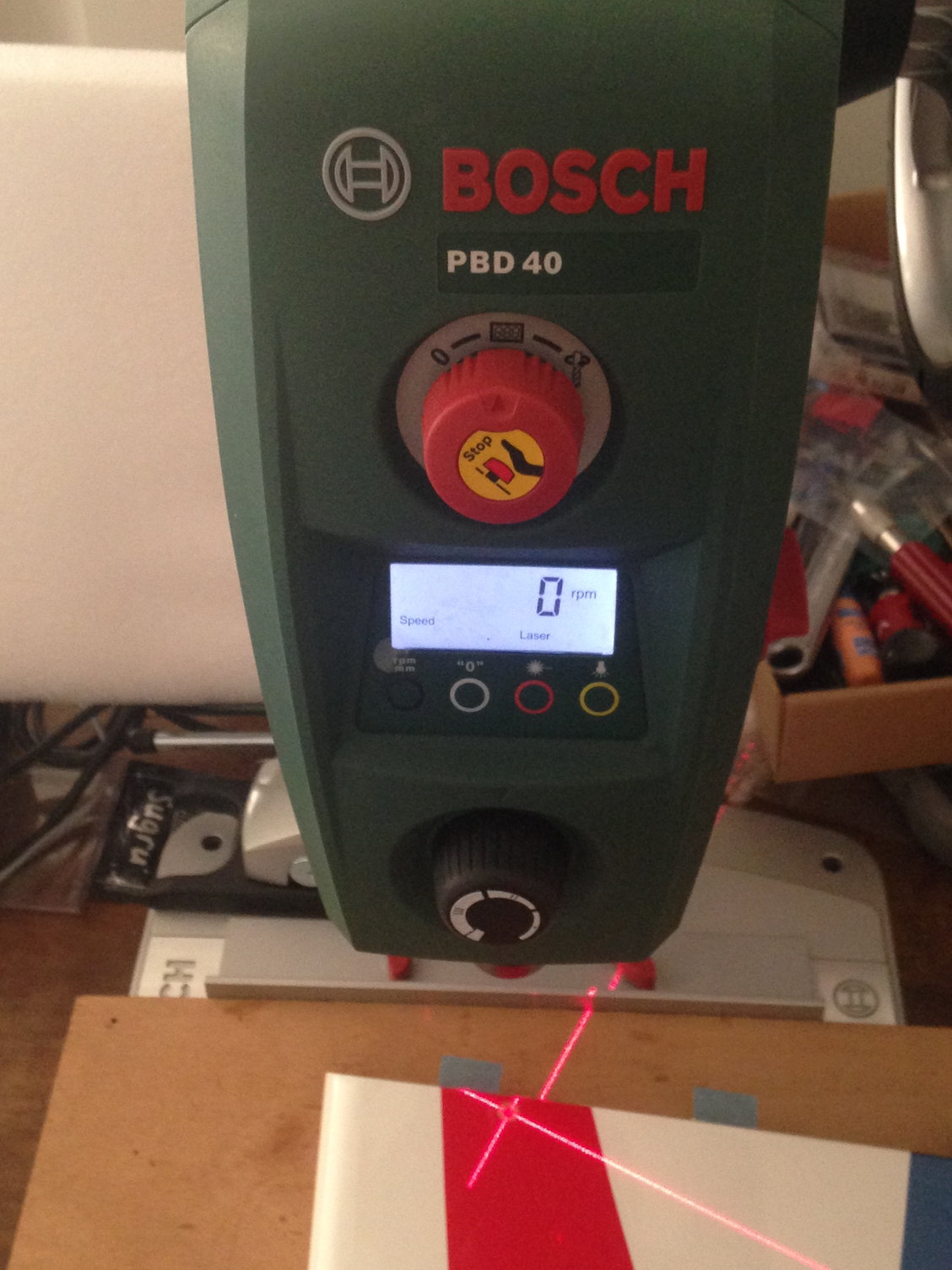
The PDB40 is 240VAC only and not imported to the USA
It is available for online purchase (free worldwide shipping) if you can provide 230VAC directly or via step up xfmr; it’s only 750W or so.
http://www.grooves-inc.com/bosch-pbd...RoCUXoQAvD_BwE
Its a nice benchtop unit with built in laser.
It is available for online purchase (free worldwide shipping) if you can provide 230VAC directly or via step up xfmr; it’s only 750W or so.
http://www.grooves-inc.com/bosch-pbd...RoCUXoQAvD_BwE
Its a nice benchtop unit with built in laser.
05-23-2018 | 01:41 PM
#33
Thread Starter
My Feedback: (1)
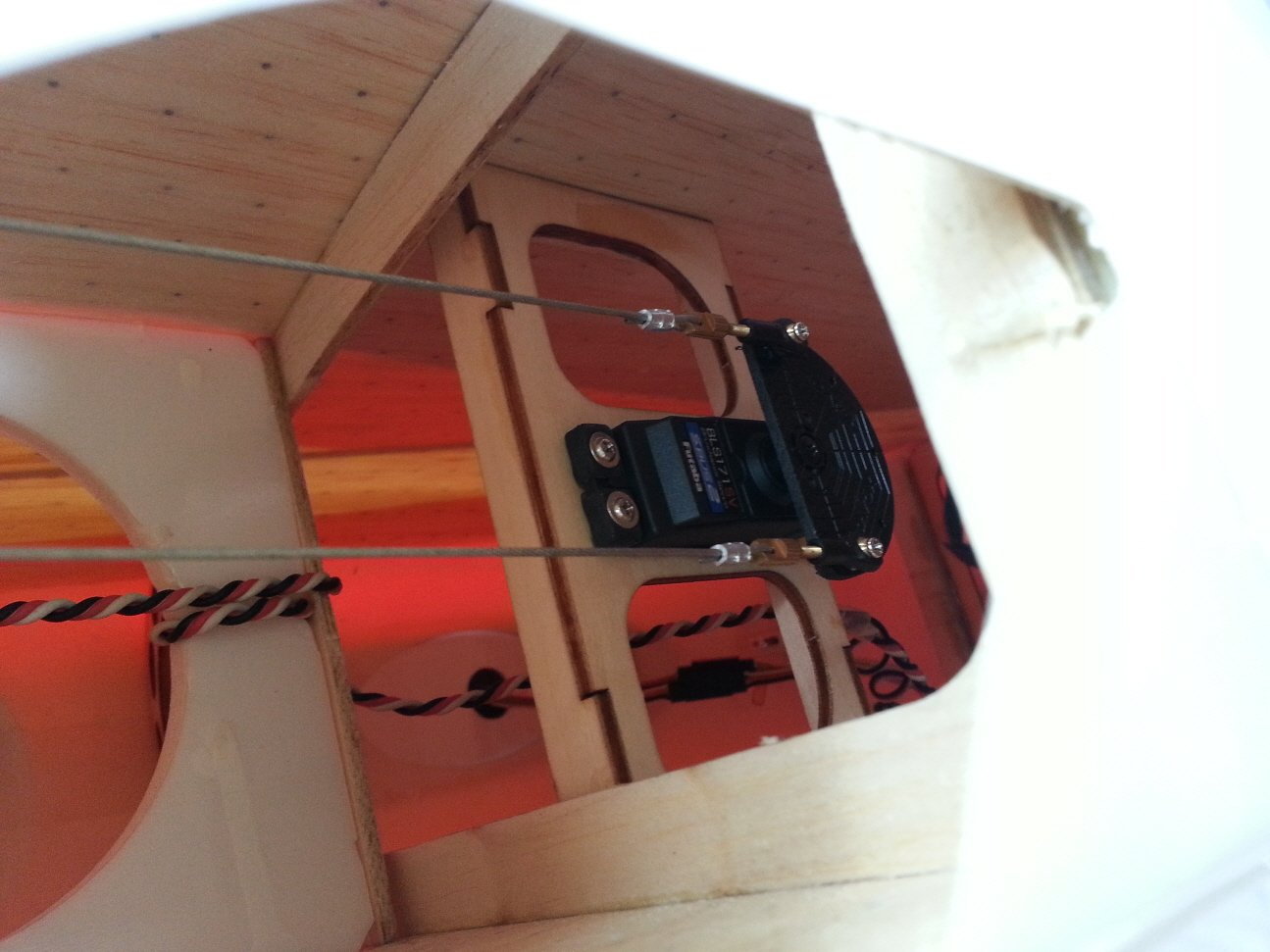
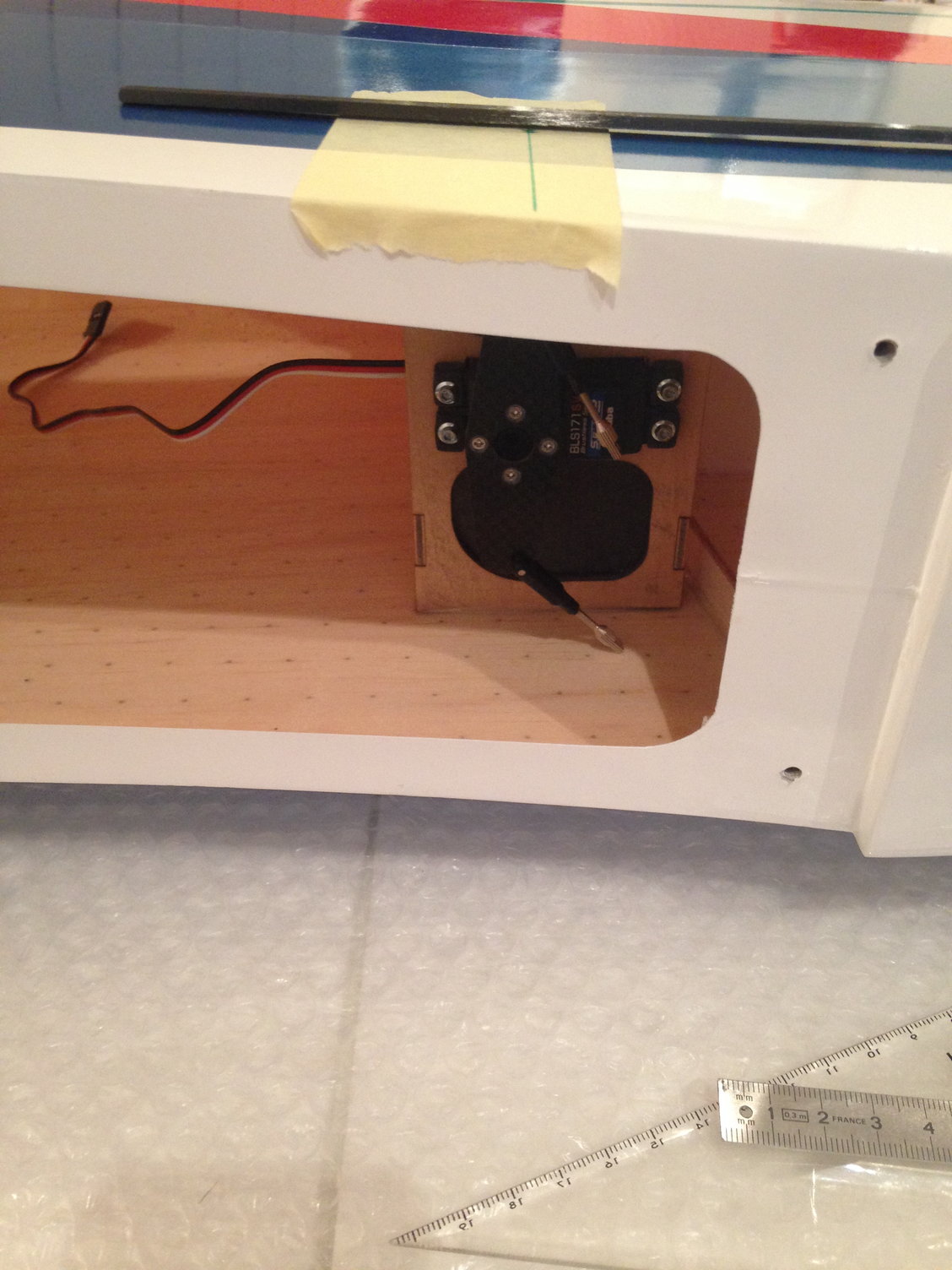
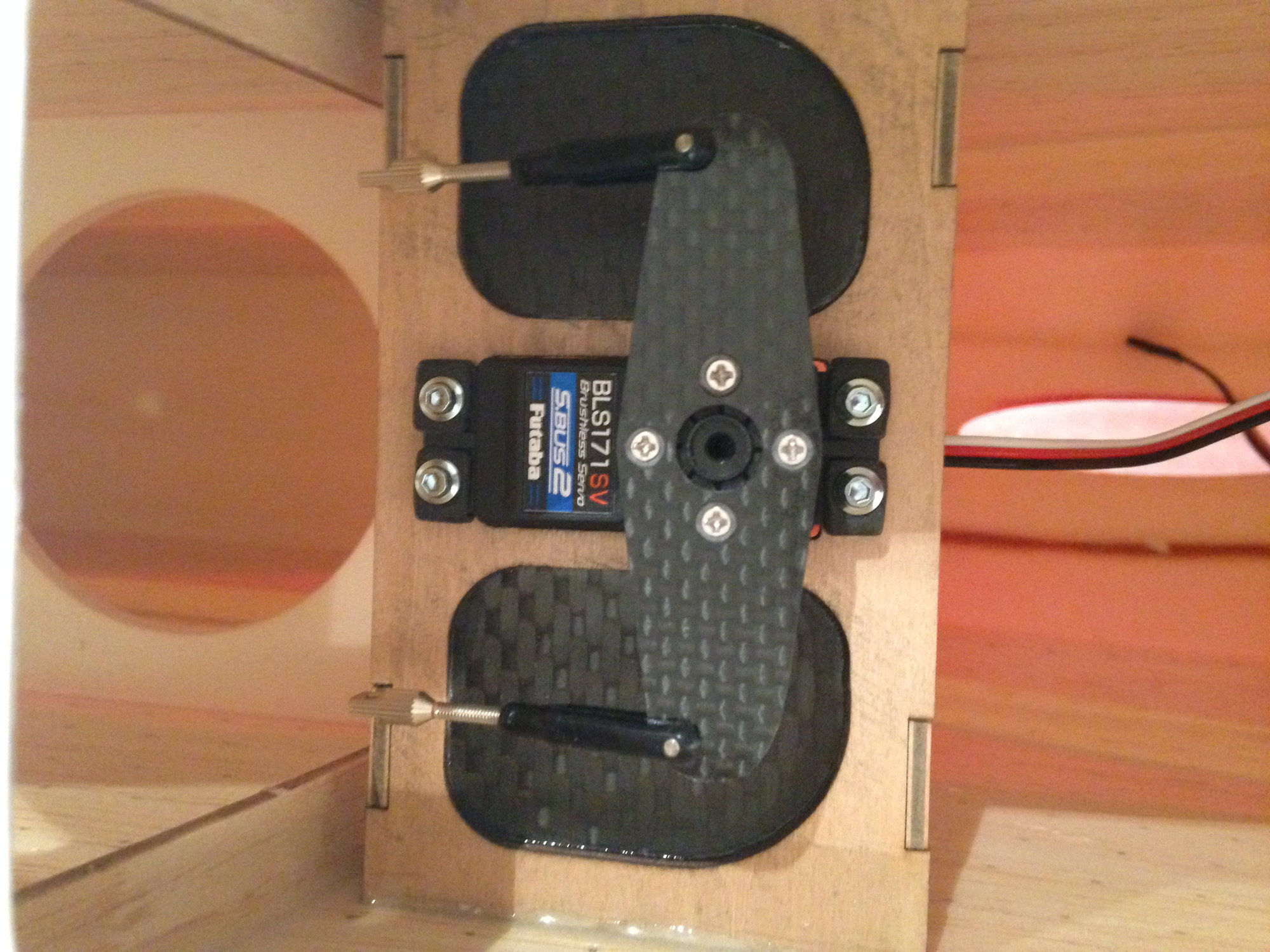
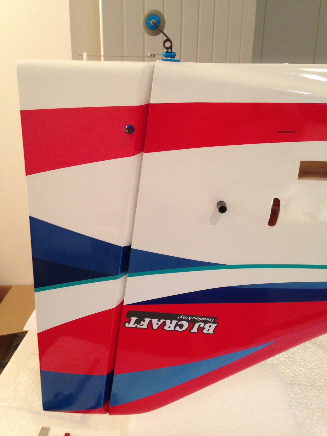
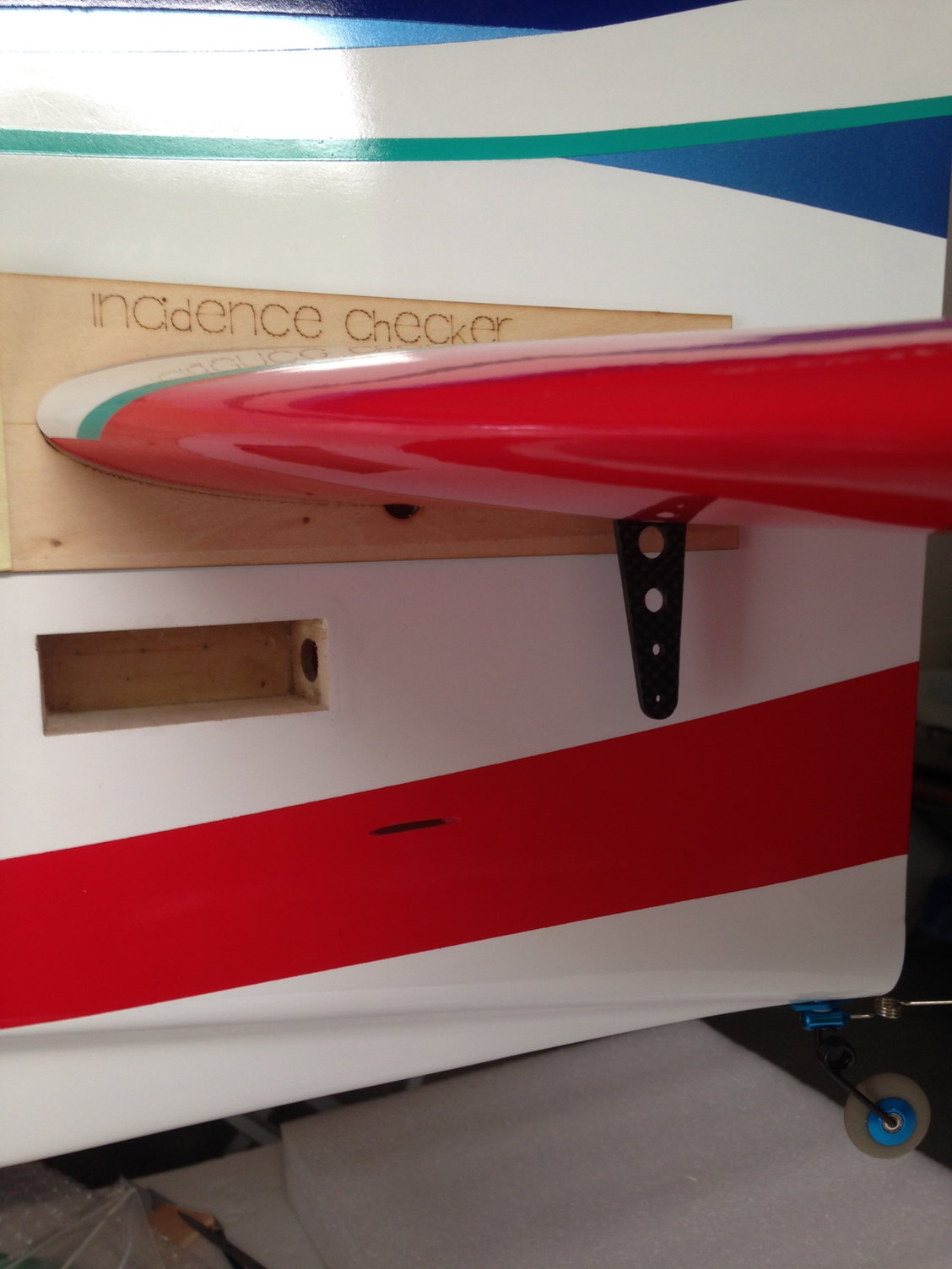
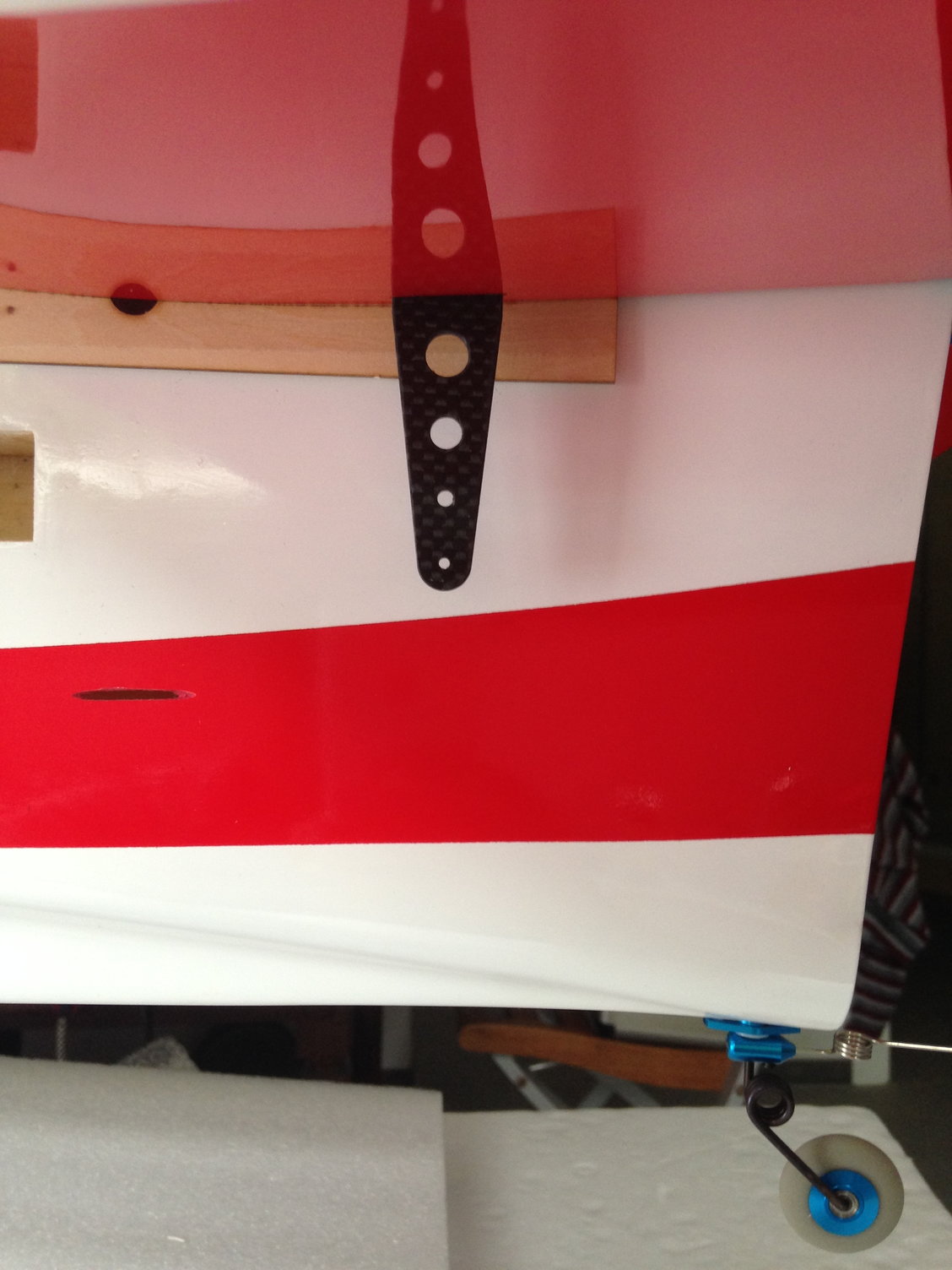
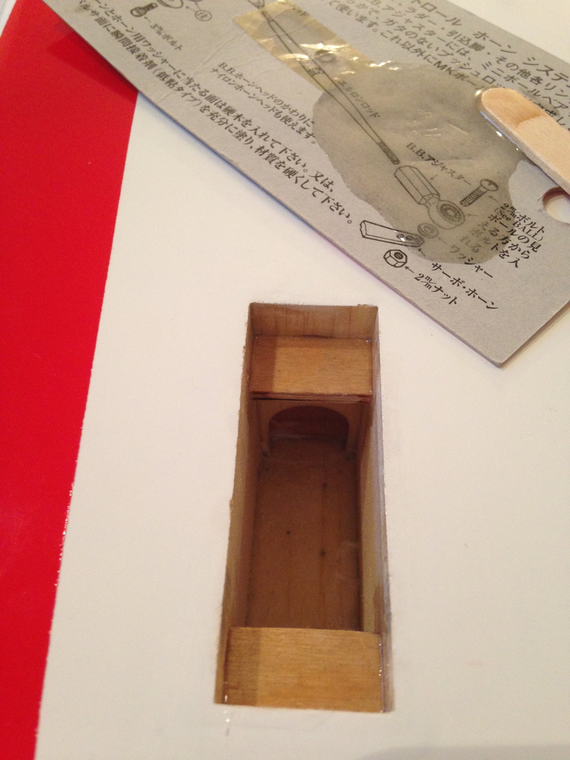
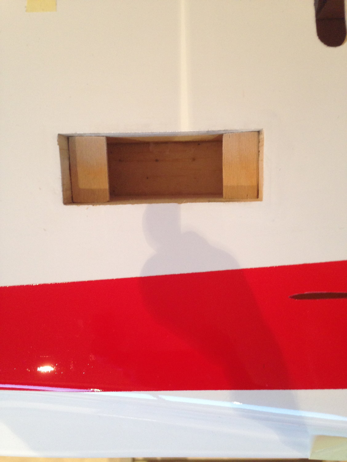
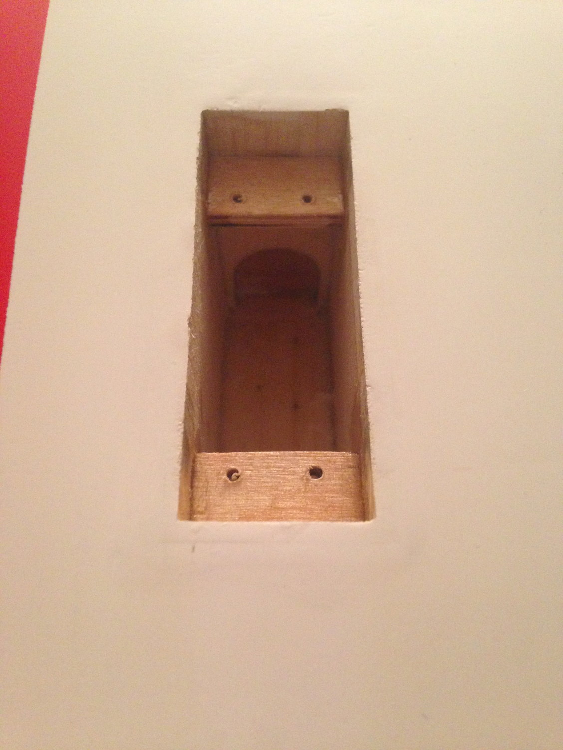
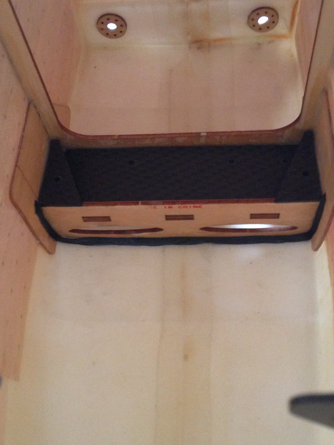
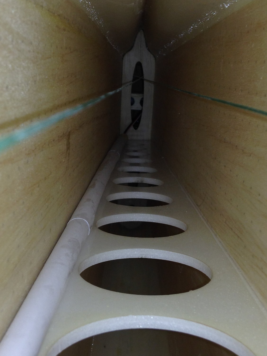
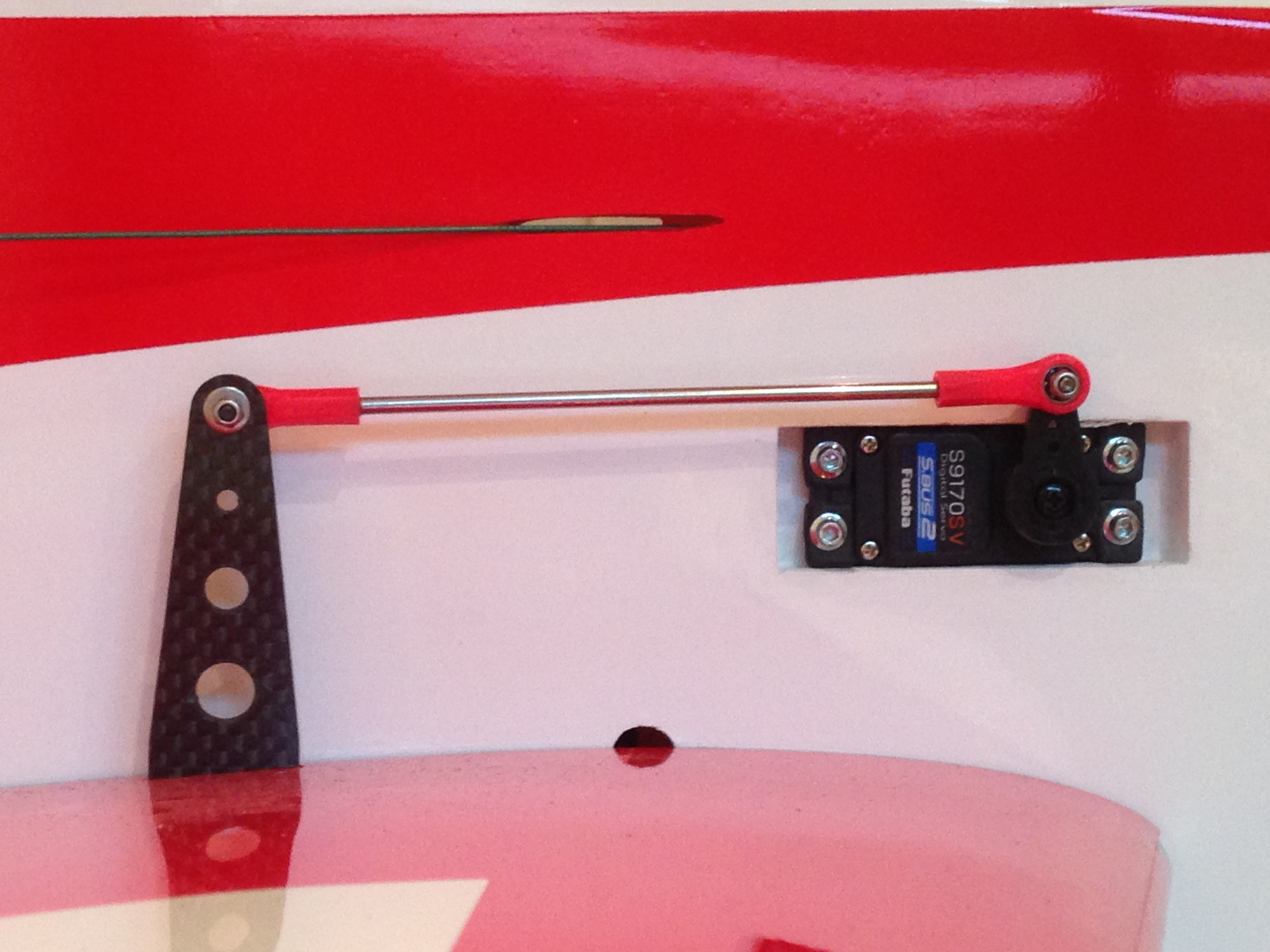
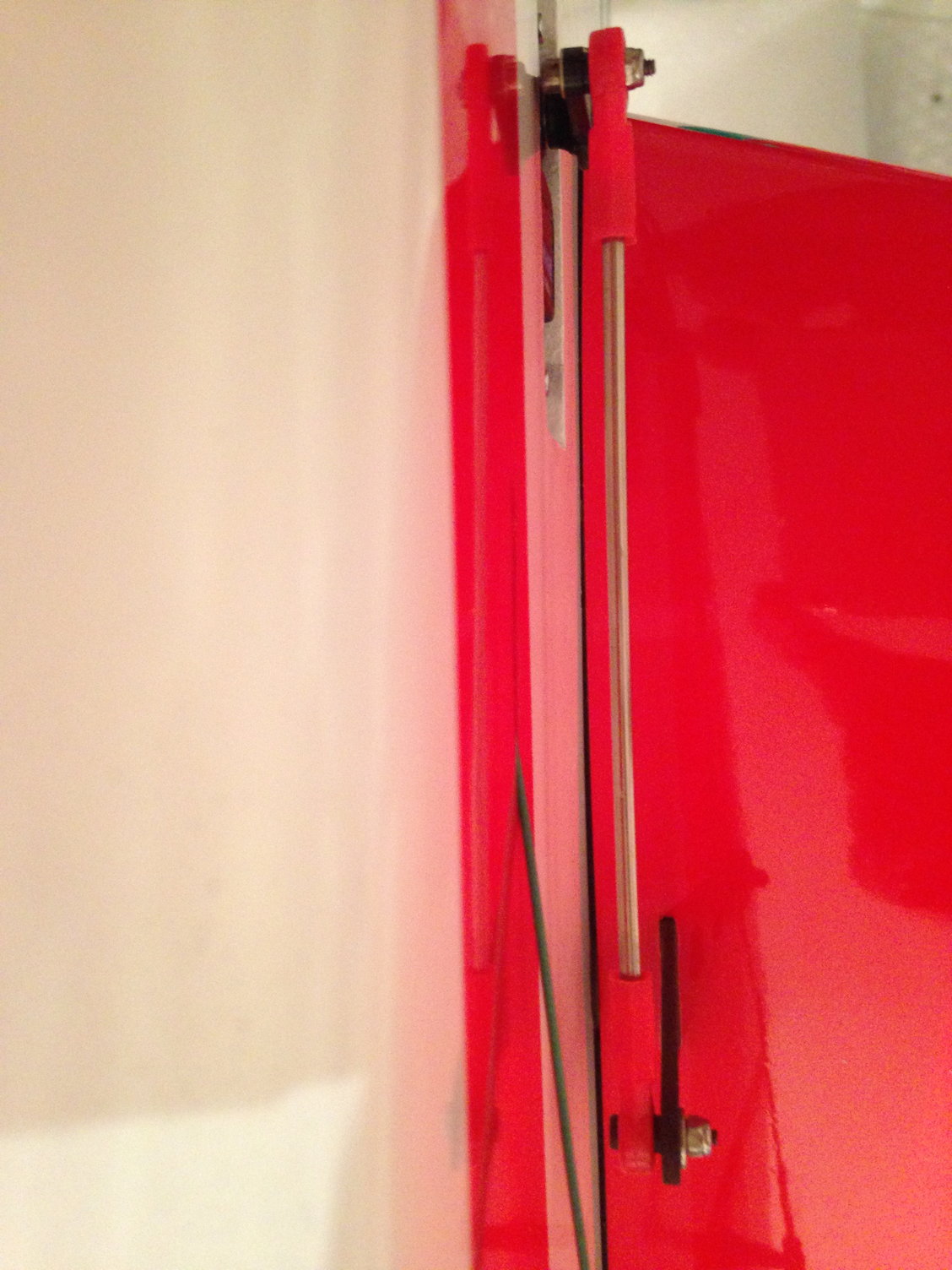
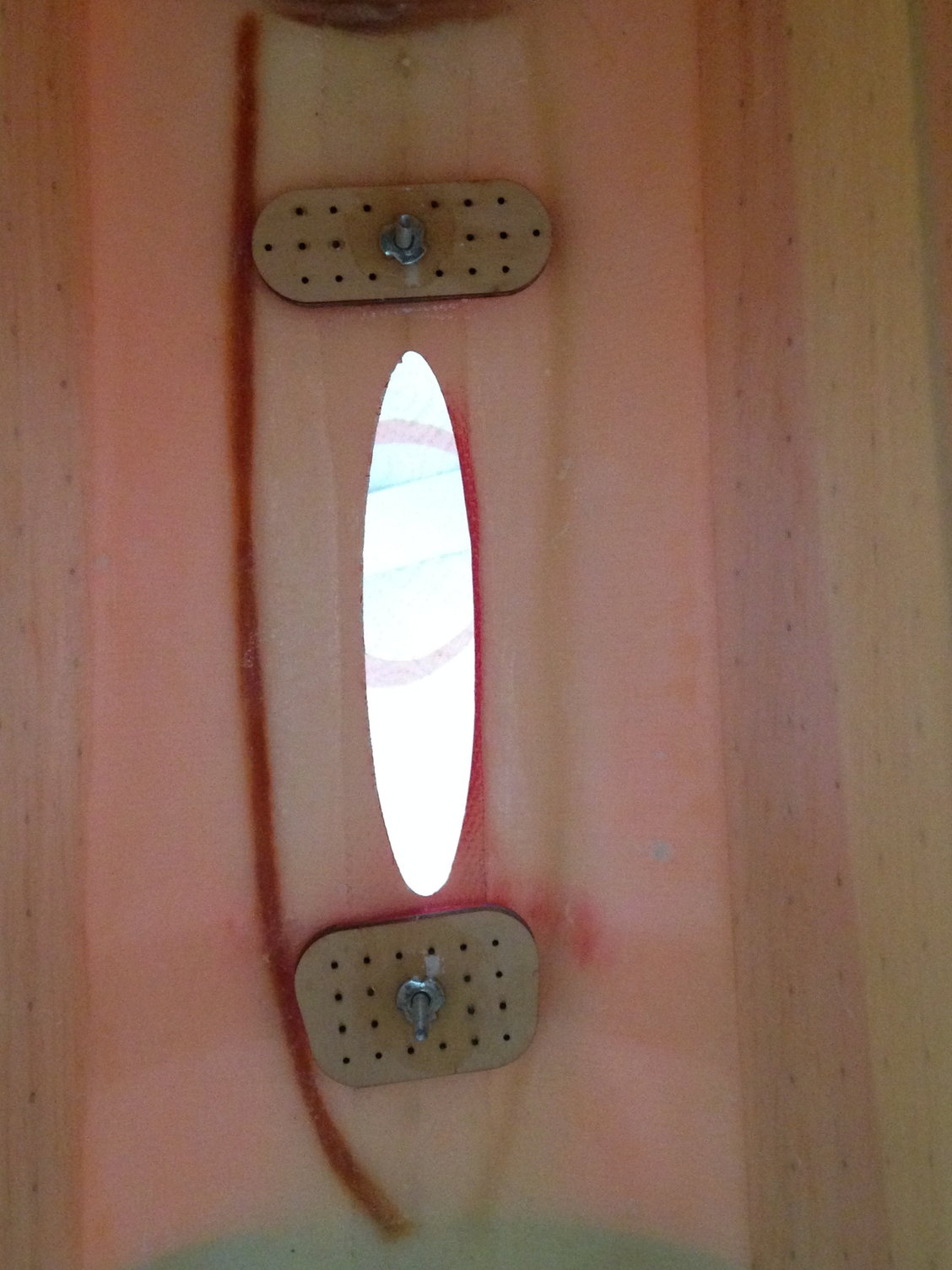
Next step is to install the rudder tray, in line with the rudder horns.
I used two 4 X 4 mm hard balsa glued with CA to position perfectly the rudder tray glued with epoxy.
Rudder servo arm holes are 61 mm distant to match the rudder horn holes.
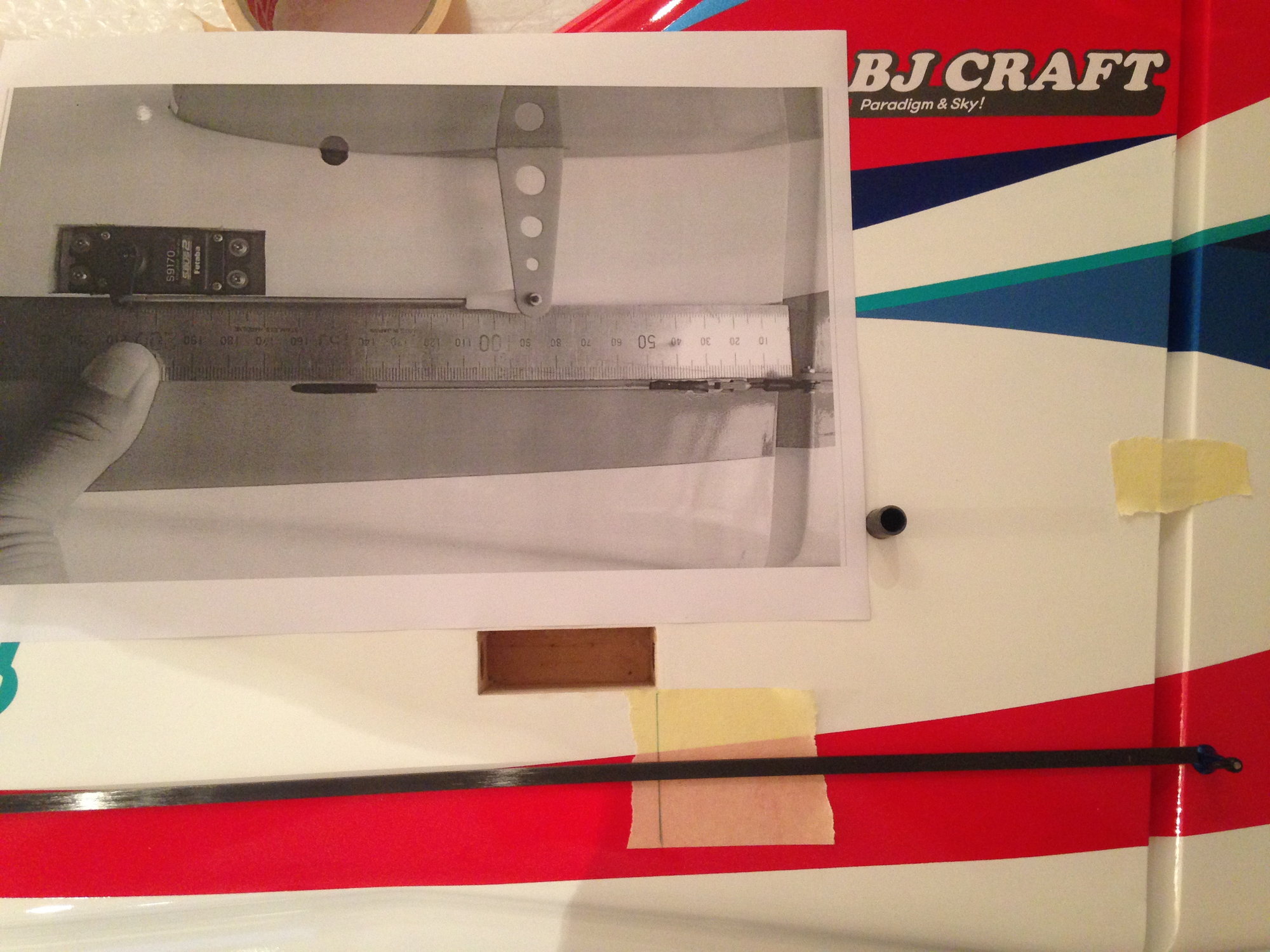
The picture sent by B.J.CRAFT for the rudder exit cables position is accurate, and I found quite the same location, even with a wider servo horn.
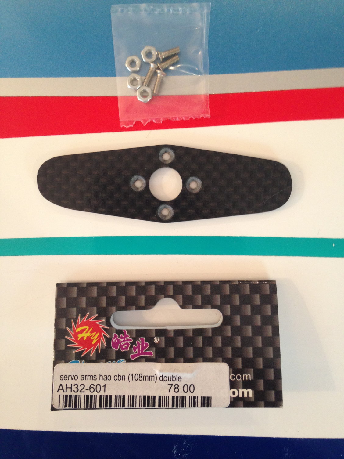
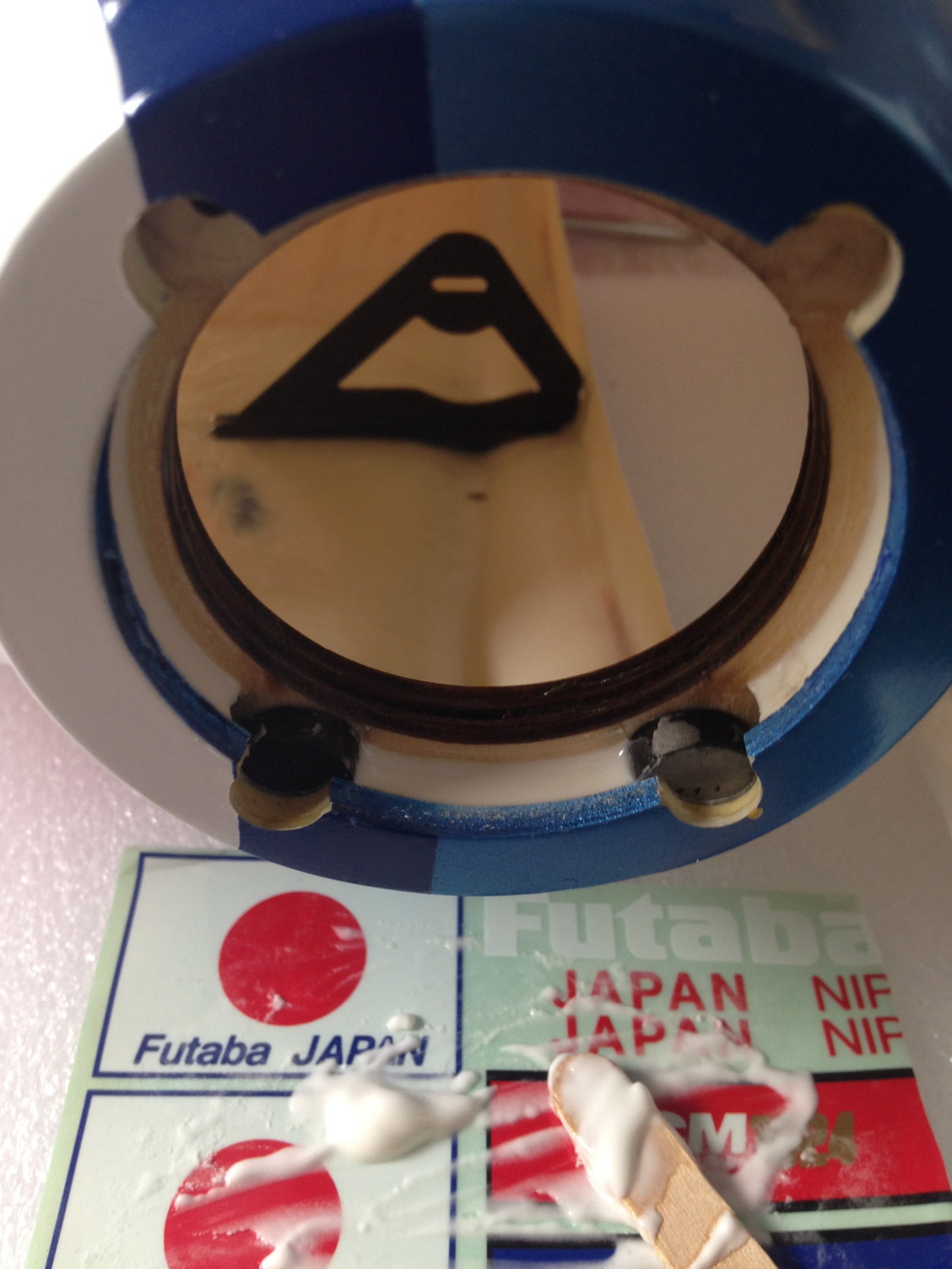
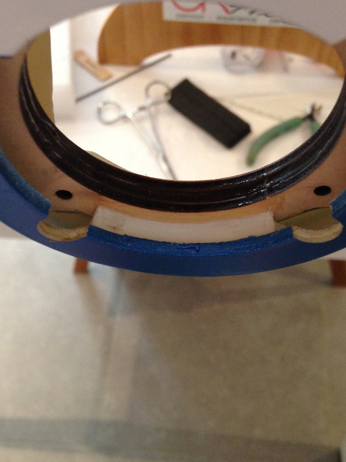
For the rudder arm, I prefer to use these aftermarket carbon parts, installed on the original FUTABA servo wheel.
Better fit, and avoid the problems with carbonite output gear when used with aftermarket metallic horns.
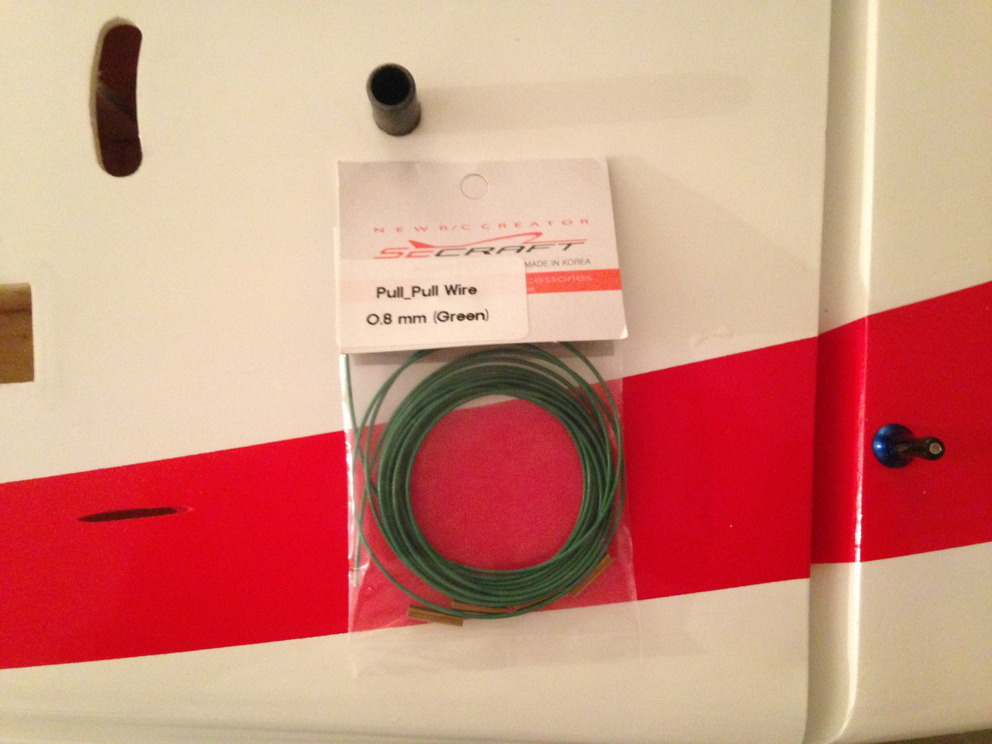
Fuselage is now ready for the pull pull wire, the green 0,8 mm SECRAFT.

I used two 4 X 4 mm hard balsa glued with CA to position perfectly the rudder tray glued with epoxy.
Rudder servo arm holes are 61 mm distant to match the rudder horn holes.
The picture sent by B.J.CRAFT for the rudder exit cables position is accurate, and I found quite the same location, even with a wider servo horn.
For the rudder arm, I prefer to use these aftermarket carbon parts, installed on the original FUTABA servo wheel.
Better fit, and avoid the problems with carbonite output gear when used with aftermarket metallic horns.
Fuselage is now ready for the pull pull wire, the green 0,8 mm SECRAFT.
05-24-2018 | 12:26 PM
#34
Thread Starter
My Feedback: (1)
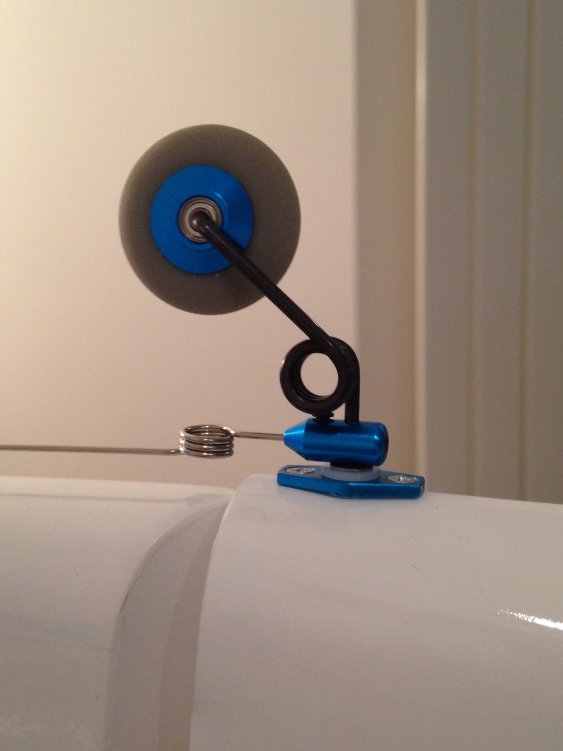
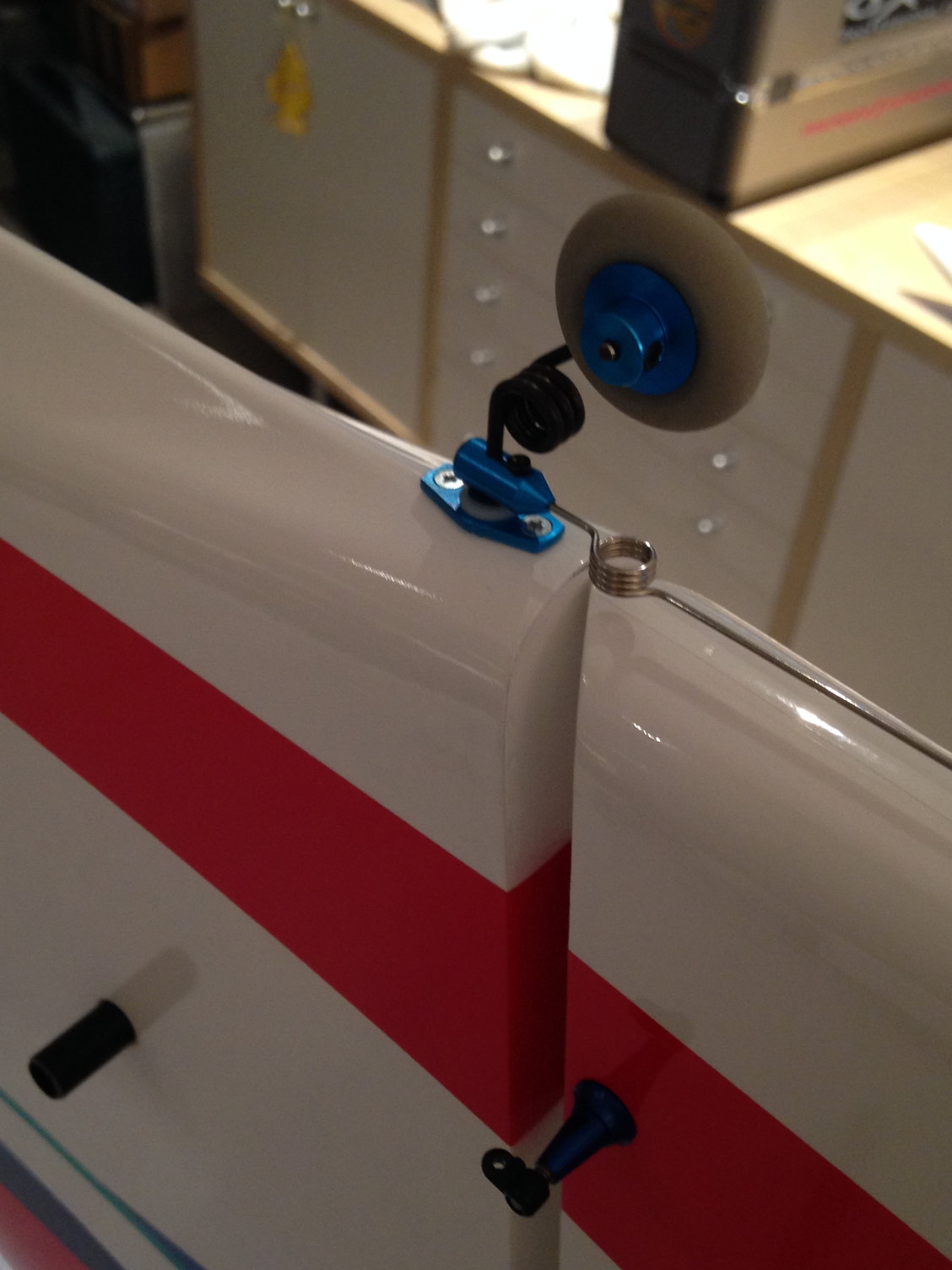
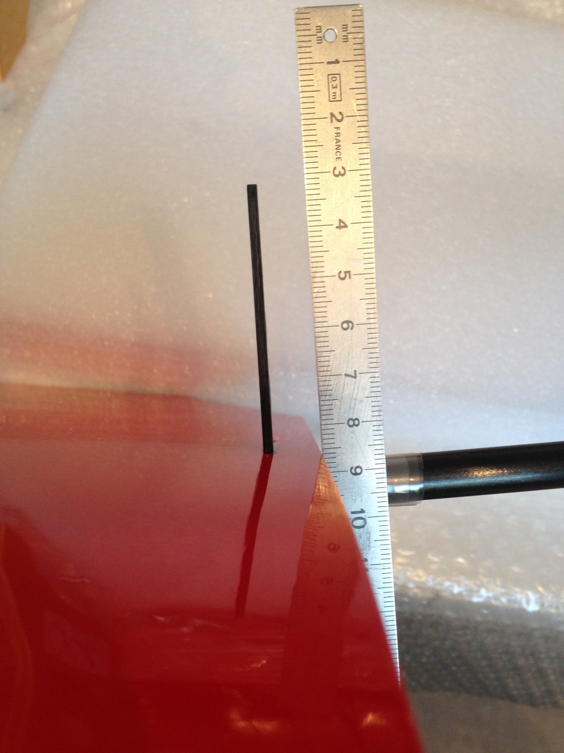
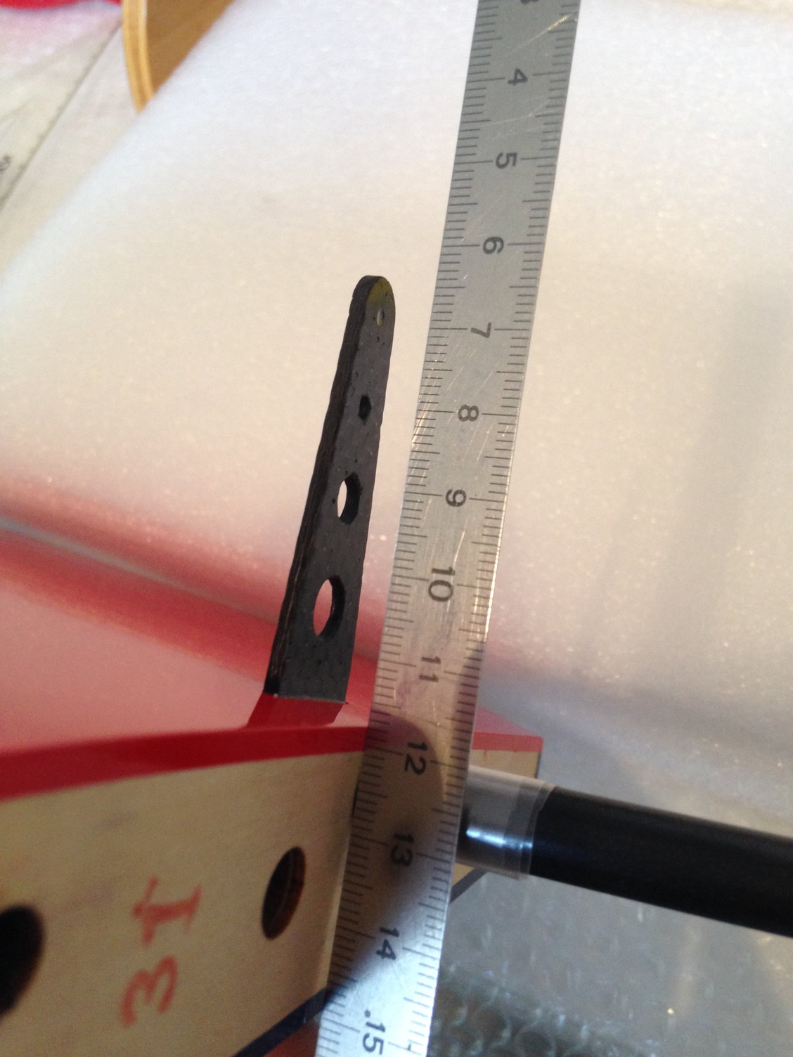
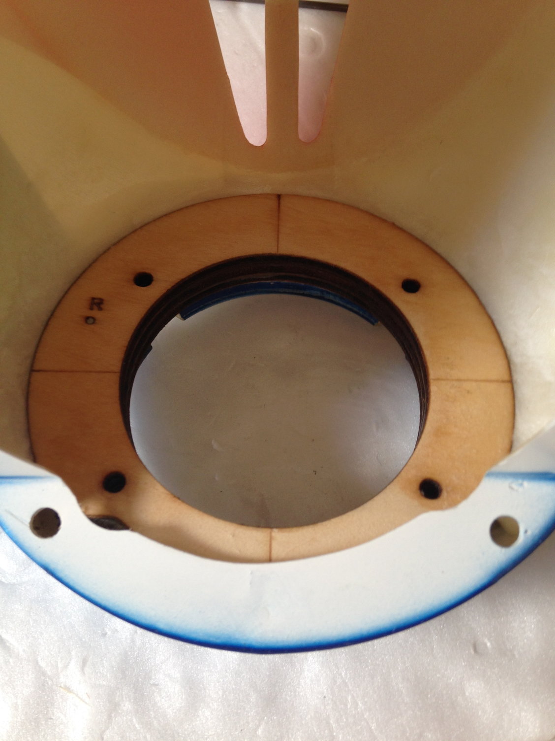
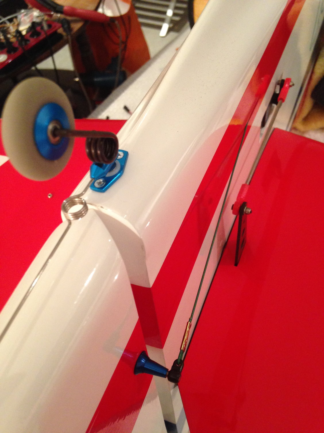
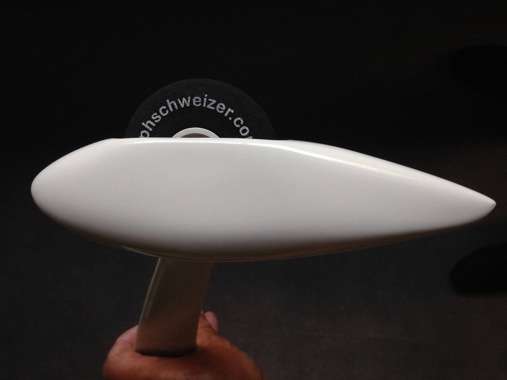
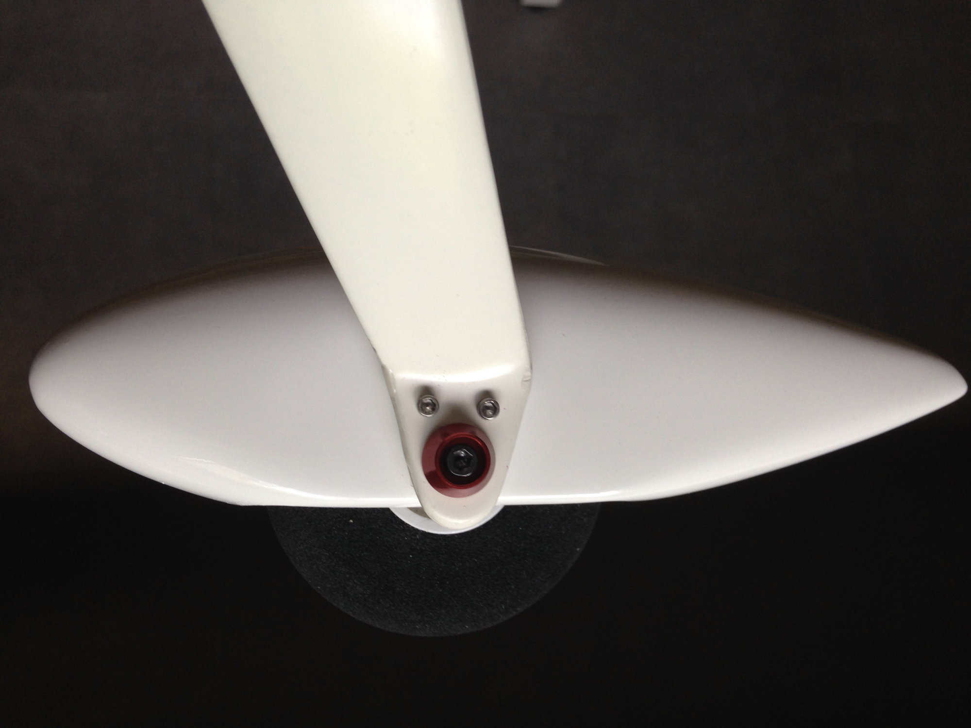
While being on the rudder I installed the tail wheel.
This is a Japanese aftermarket one imported in Europe by Ralph Schweizer.
You have to drill a 7mm hole for the tail wheel axle, and then a 4 mm hole in the rudder.
Two drops of CA after thread, and just screw in the small plastic part.
The tail wheel is held in position by 2 small screws.
With the tail wheel installed, it looks like more to a plane now.
05-28-2018 | 12:46 PM
#35
Thread Starter
My Feedback: (1)
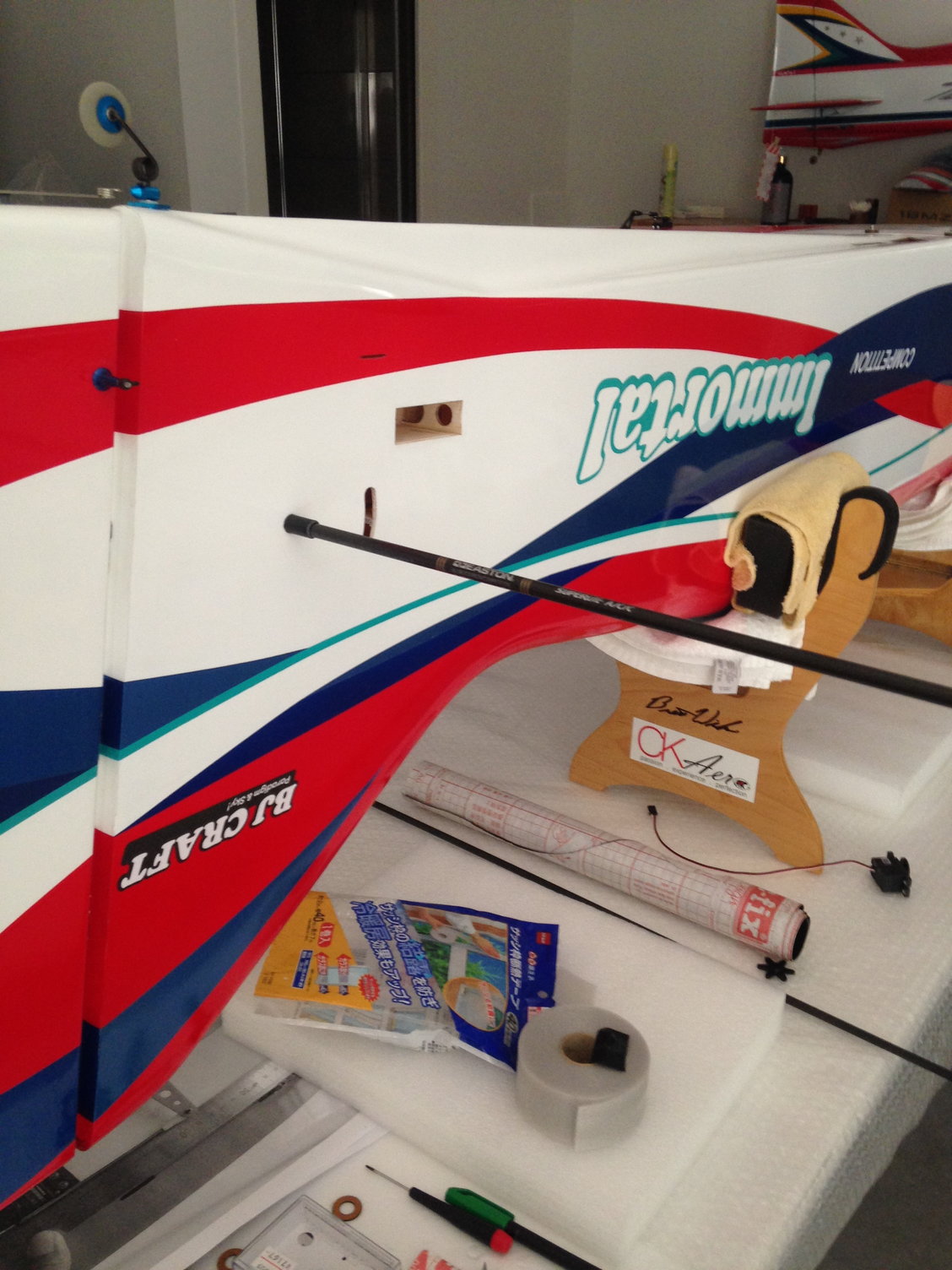
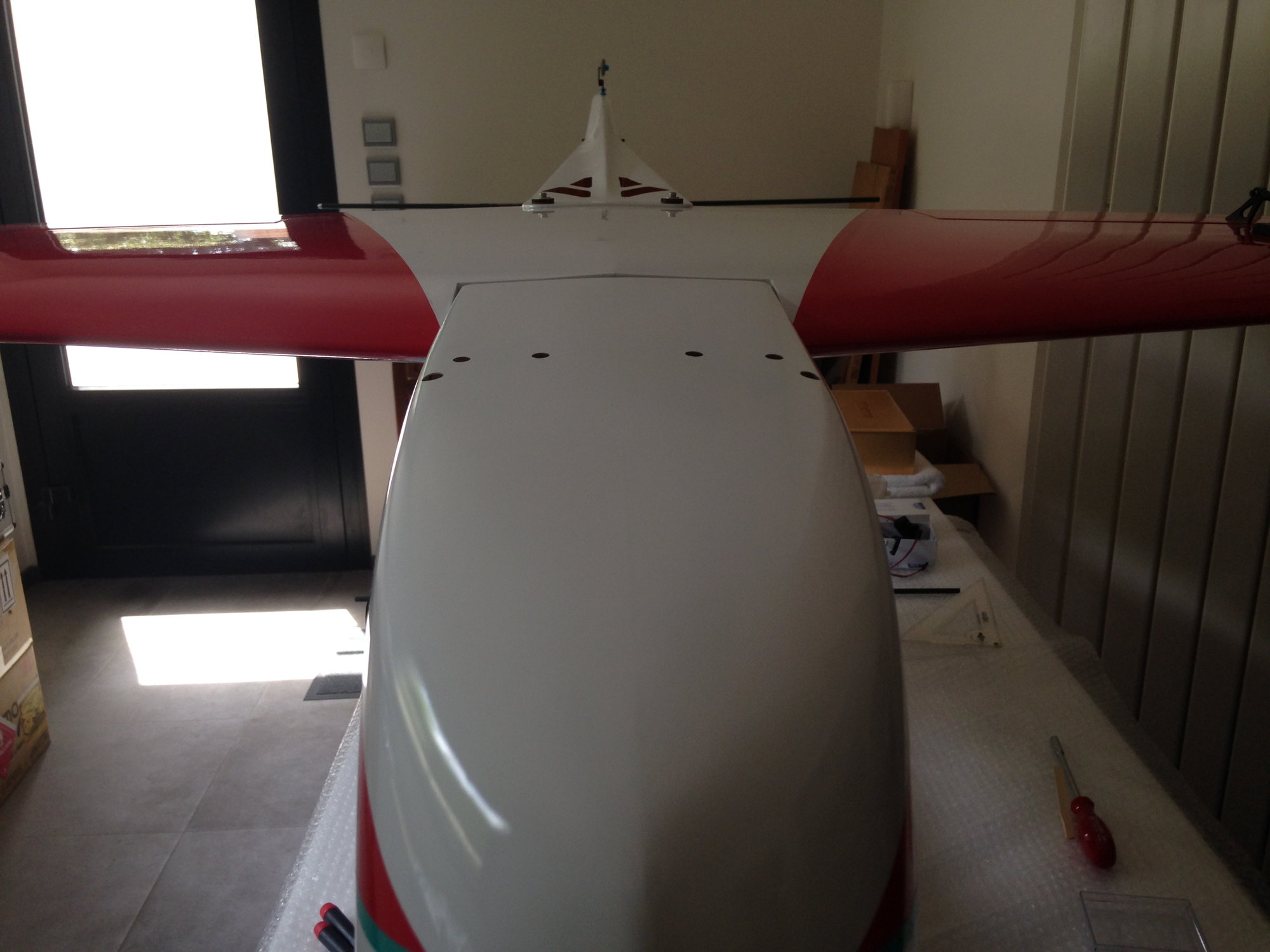
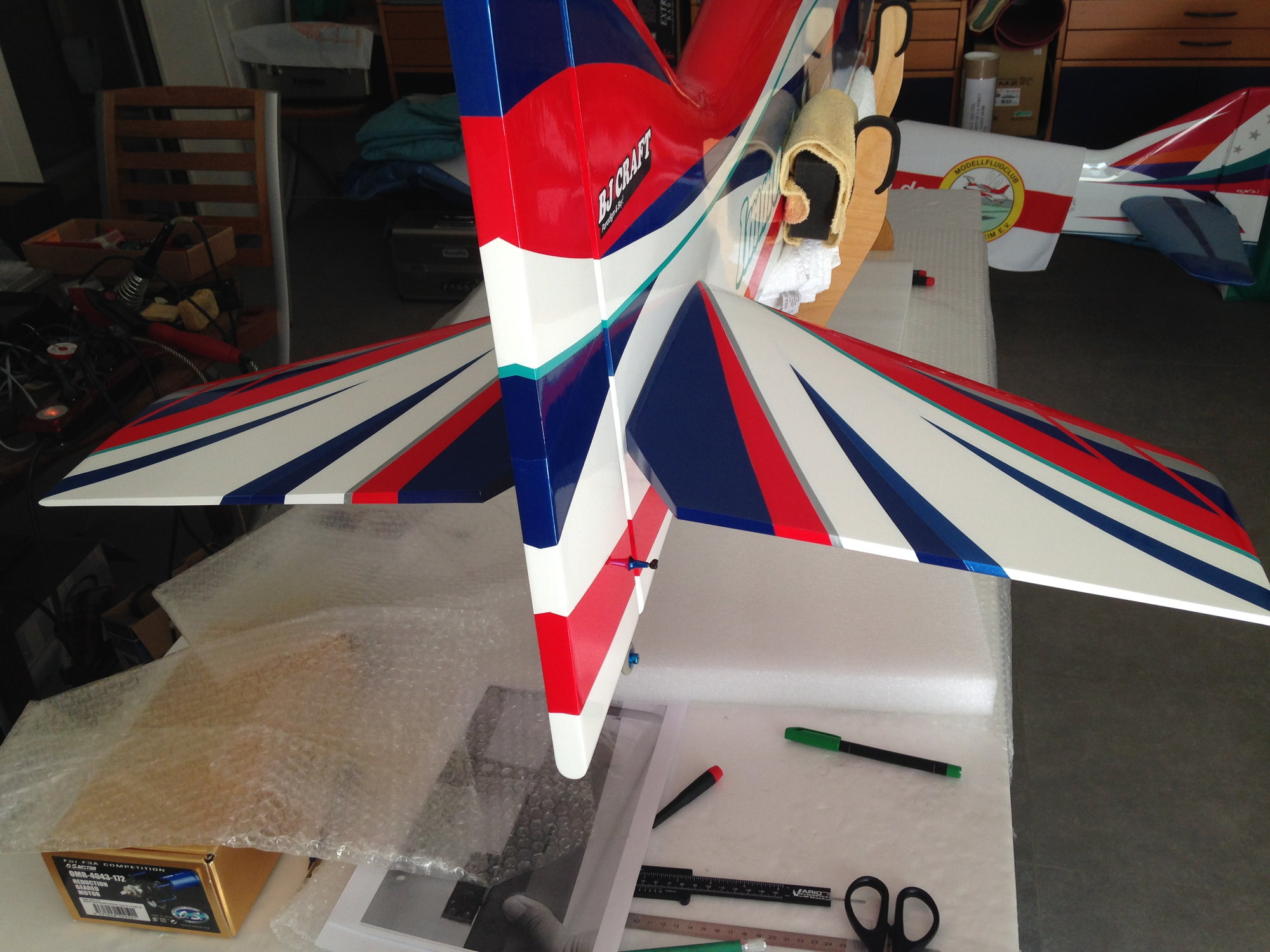
I can't emphasize how much important it's to have the stab parallel to the wings ...
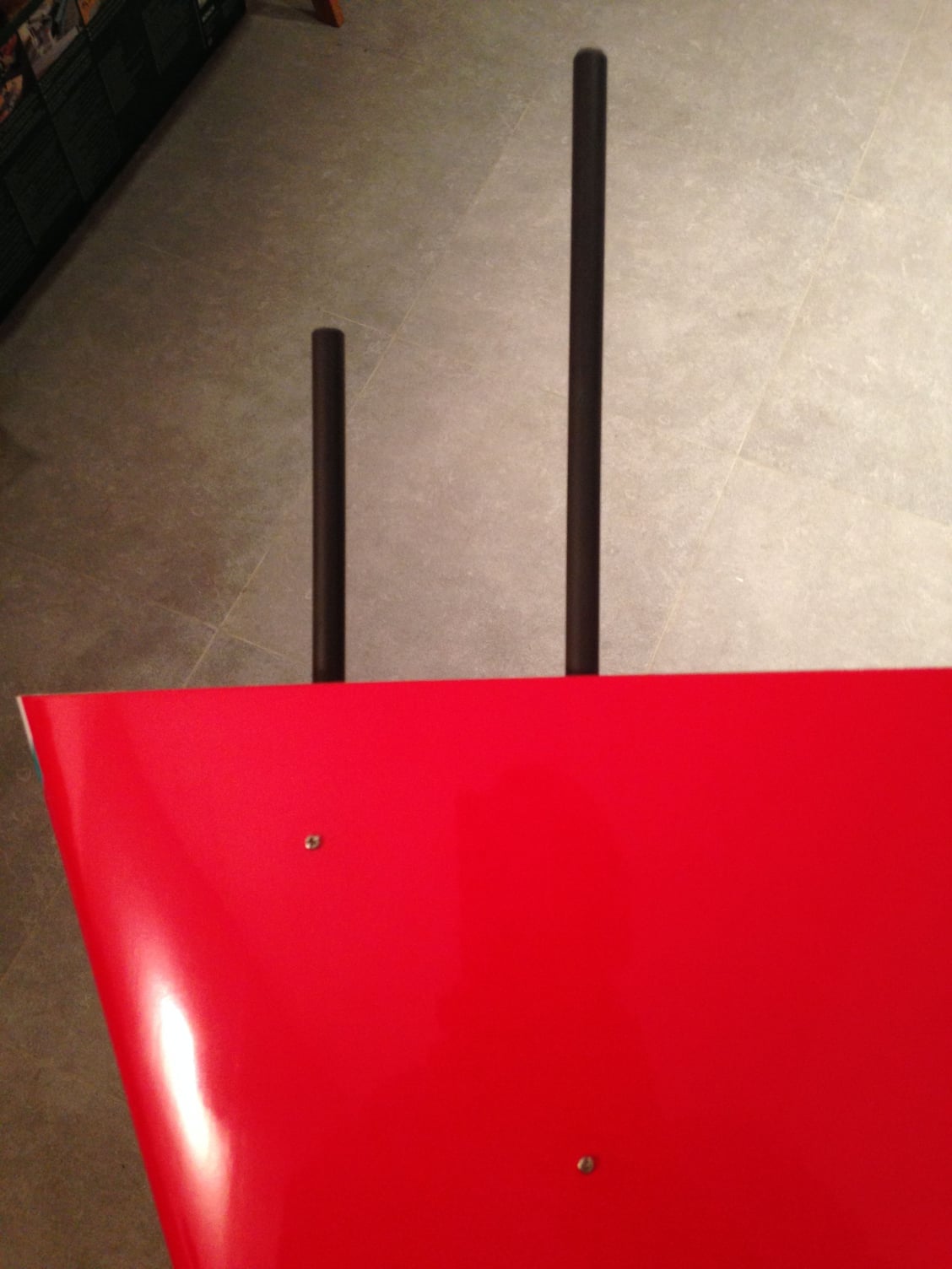
So in order to position the main tube of the flying stab, I'm not using a carbon tube, but an arrow I bought in LA when I was flying a Jekyll with Greg OKKERT and Warren FOX in Mile square Park ....
This arrow is made of carbon outside, and aluminium inside, so perfectly straight.
The alignment from the factory was perfect, so I didn't did any adjustment.
Just gluing the main tube with CA, then I positioned both stabs to check for the carbon tubes length , and the clearance I want between the stabs and the fuselage.
Locating the hard wood in the stab is easy. After marking the center, I drilled 1,8 mm holes in the right stab and carbons tubes.
Last edited by J-P; 05-28-2018 at 12:59 PM.
06-20-2018 | 04:20 AM
#36
Thread Starter
My Feedback: (1)
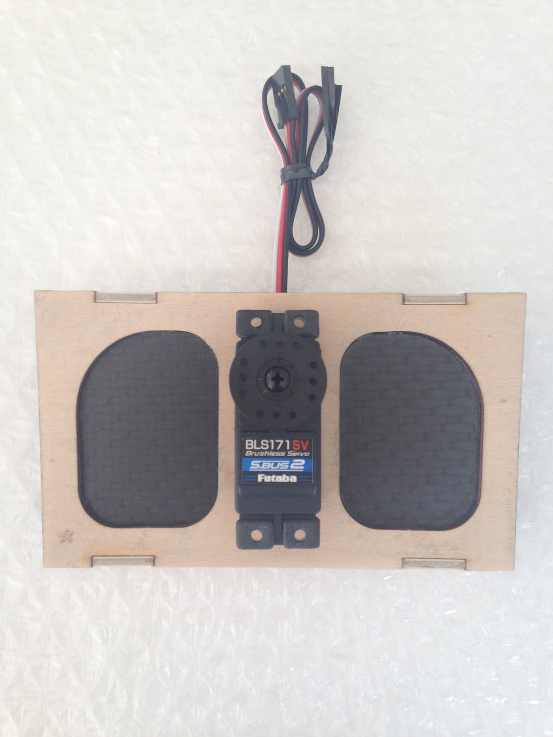
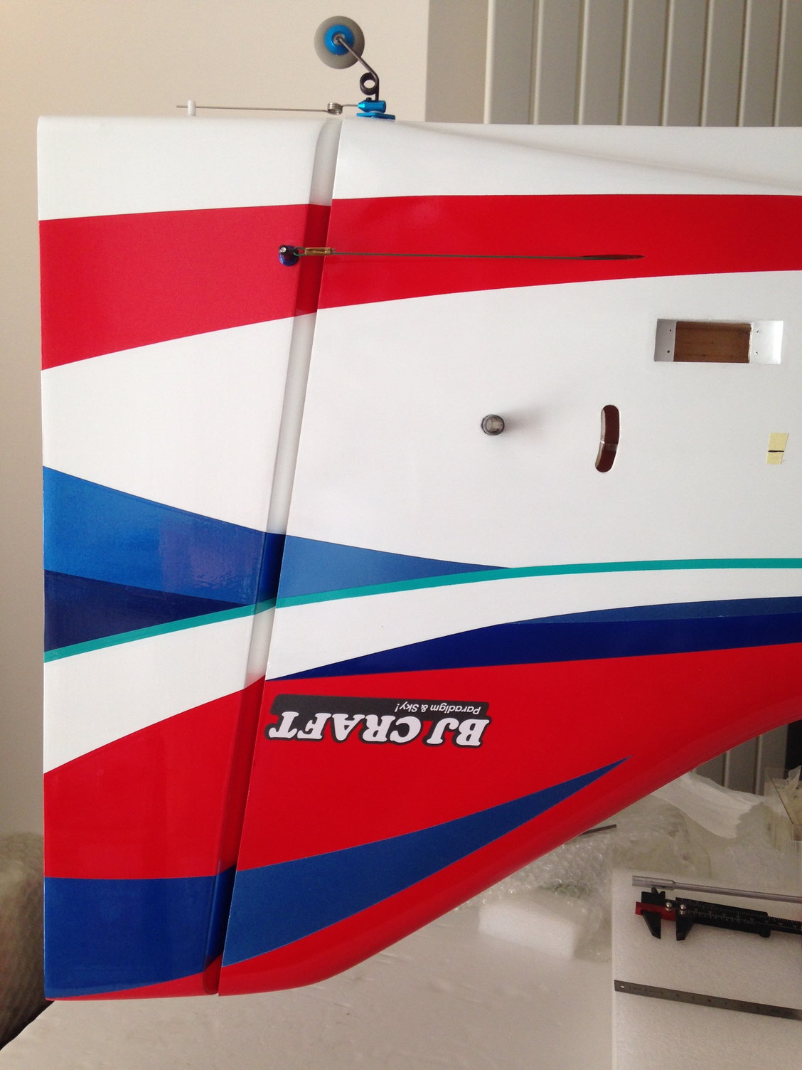
I am using the Futaba S9170SV SBUS servo.
B.J. recommends this servo for the elevator. It has great centering and holding capability which are important for the flying stab. It is also light which helps keep the weight down in the tail.
Positioning correctly the elevator servo is important to have the command parallel to the fuselage.
You have to check for the depth before installing, according what you are using ...
I used two 2,5 mm Kato ball bearing clevis', I have some in stock left ....
Everything must be set at 90 �, and the elevator control horn, glued with 30 mn epoxy must be parallel to the fuselage too.
Some venilia velvet on both halves of the stab will give a smooth friction and no gap between the fuselage.
Last edited by J-P; 06-20-2018 at 04:24 AM.


 06-27-2018 | 12:59 PM
#39
Thread Starter
My Feedback: (1)
After gluing the rudder with epoxy , I installed in the fuselage a homemade paper tube to guide the elevator servo cord extension.
Stab tubes are epoxied too in the left stab.
Last work of the day, installing the connecting rod and programming the elevator flight conditions.
Stab tubes are epoxied too in the left stab.
Last work of the day, installing the connecting rod and programming the elevator flight conditions.
06-30-2018 | 10:04 AM
#42
My Feedback: (3)
It's not included in the kit .... but you can order it in Japan or here in Austria
Ralph Schweizer
Ralph Schweizer
https://www.precisionaeroproducts.co...eel-assemblies
as well as Morris Hobby in Japan:
�r�W
Both are very nice to deal with, as with Ralph Schweizer as well.
07-01-2018 | 11:13 AM
#43
Thread Starter
My Feedback: (1)
I secured the wheels pants with two tiny bolts and blind nuts from Micro fasteners, and used Ralph Schweizer light wheels.
The gear is bolt from the top with nylstops on the bottom of the fuselage.
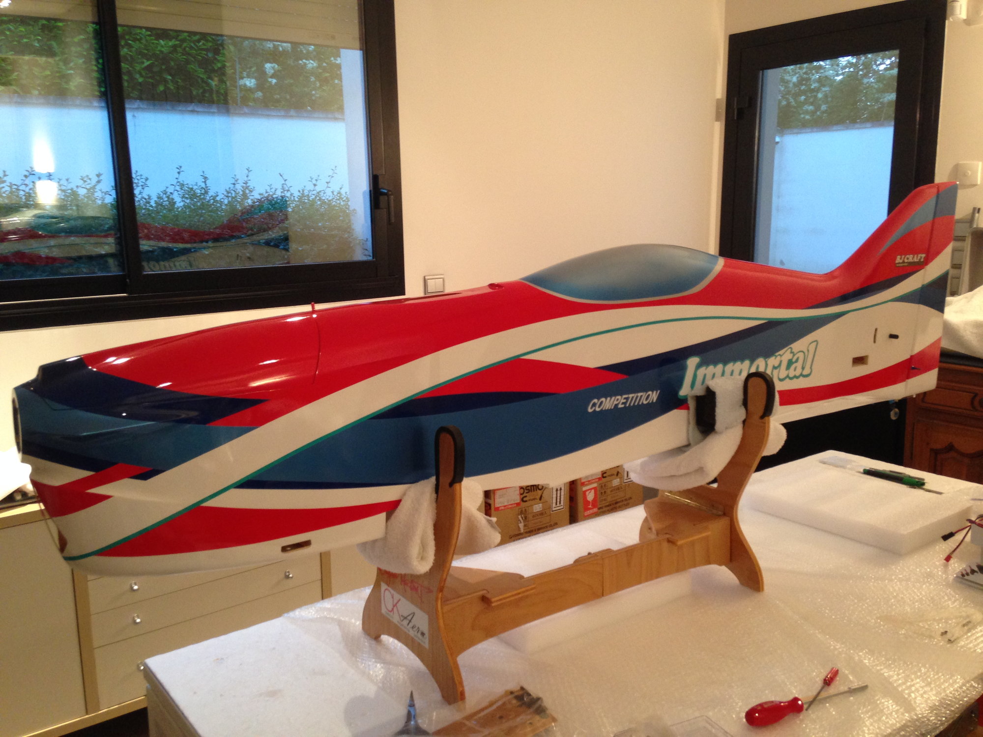
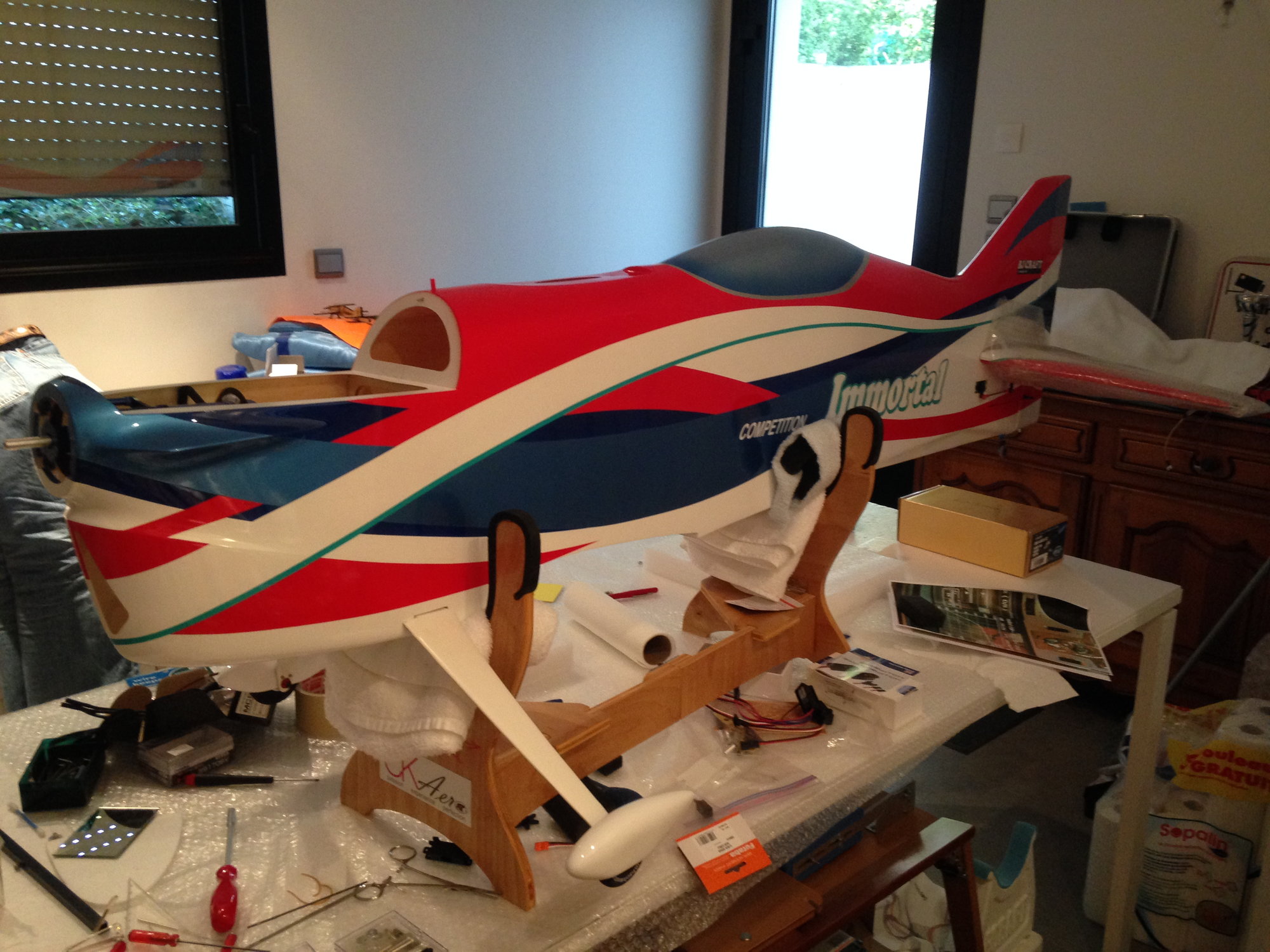
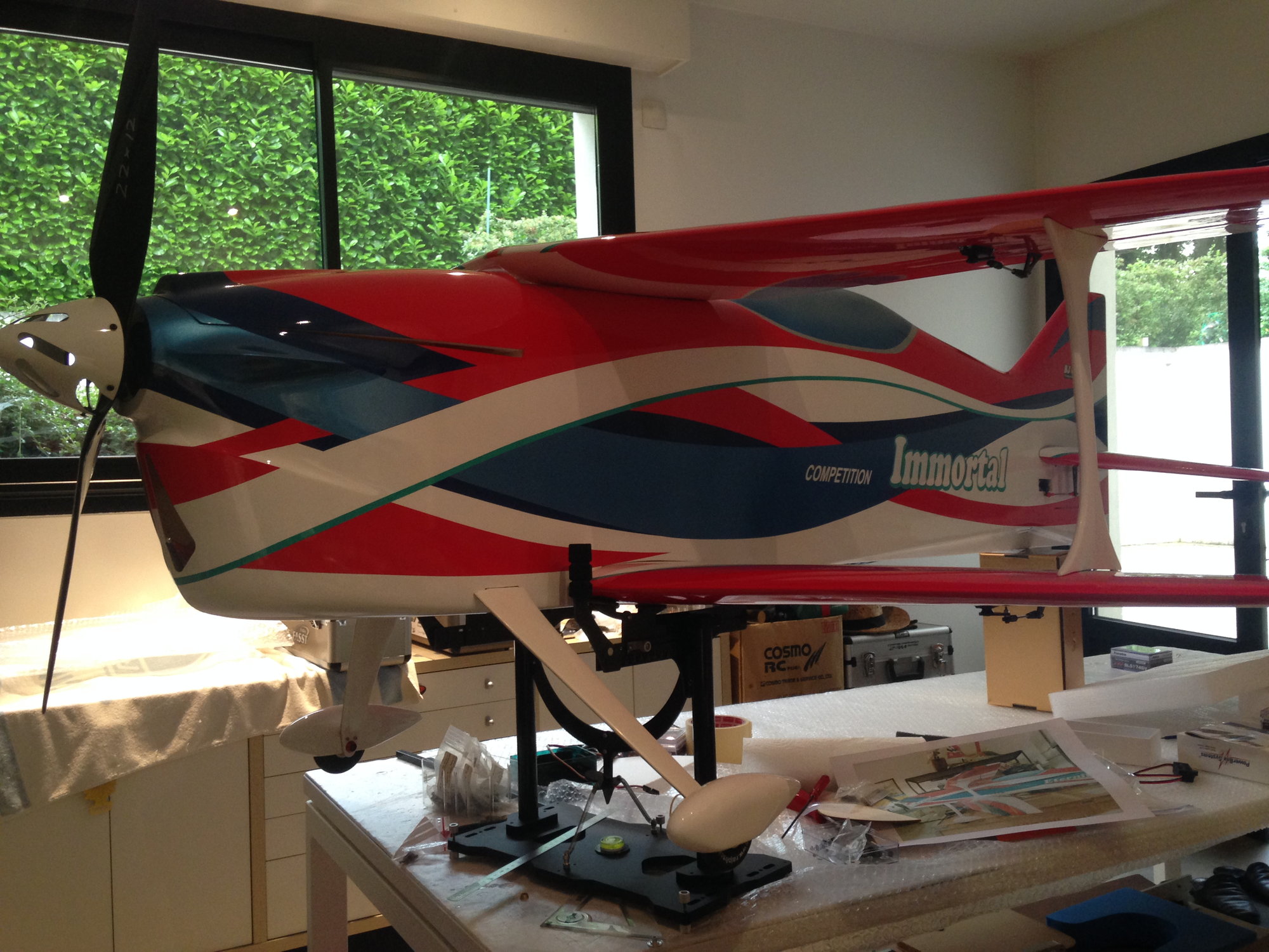
With the landing gear bolt on, we approach from the roll out .....
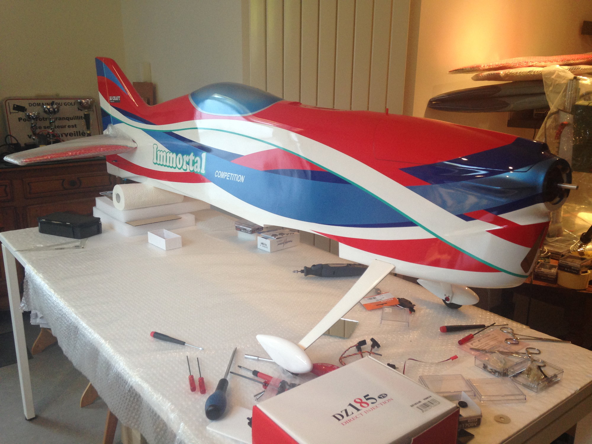
I positionned everything to weight the plane, and determine according the recommended CG by B.J. where to install the battery tray.
Final weight with 2 x 5S 5000 TP Prolite and a 900 mah backup batt come to 4750 g.
I will just have to add the battery and ESC Tray, plus some aileron servos extension.
Weight should not exceed 4850 g.

The gear is bolt from the top with nylstops on the bottom of the fuselage.
With the landing gear bolt on, we approach from the roll out .....
I positionned everything to weight the plane, and determine according the recommended CG by B.J. where to install the battery tray.
Final weight with 2 x 5S 5000 TP Prolite and a 900 mah backup batt come to 4750 g.
I will just have to add the battery and ESC Tray, plus some aileron servos extension.
Weight should not exceed 4850 g.
Last edited by J-P; 07-01-2018 at 11:15 AM.
07-01-2018 | 05:55 PM
#45
My Feedback: (3)
Last edited by ltc; 07-01-2018 at 06:17 PM.
07-10-2018 | 12:32 PM
#46
Thread Starter
My Feedback: (1)
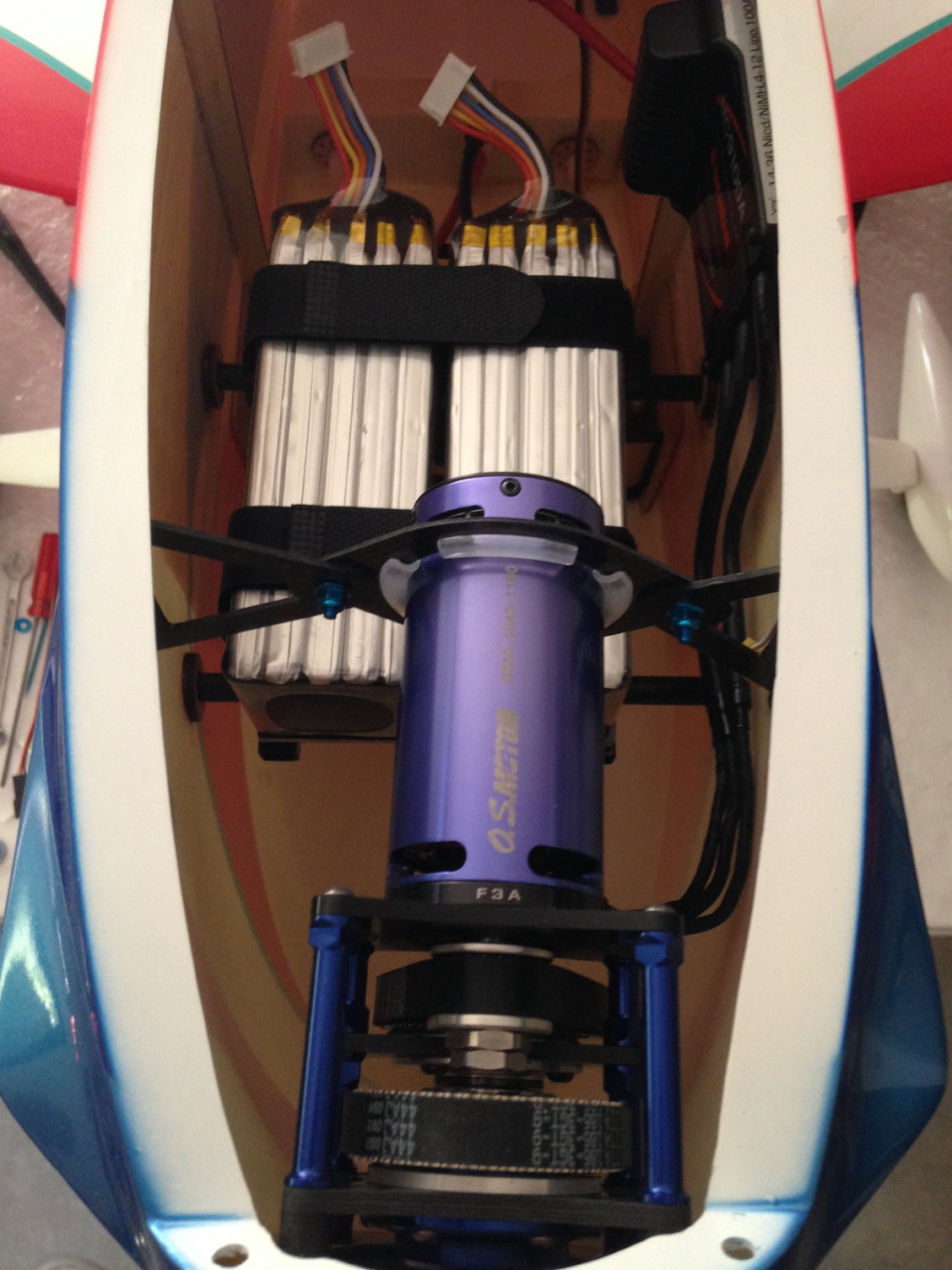
According to B.J. the CG is located at 130 mm from the low wing leading edge.
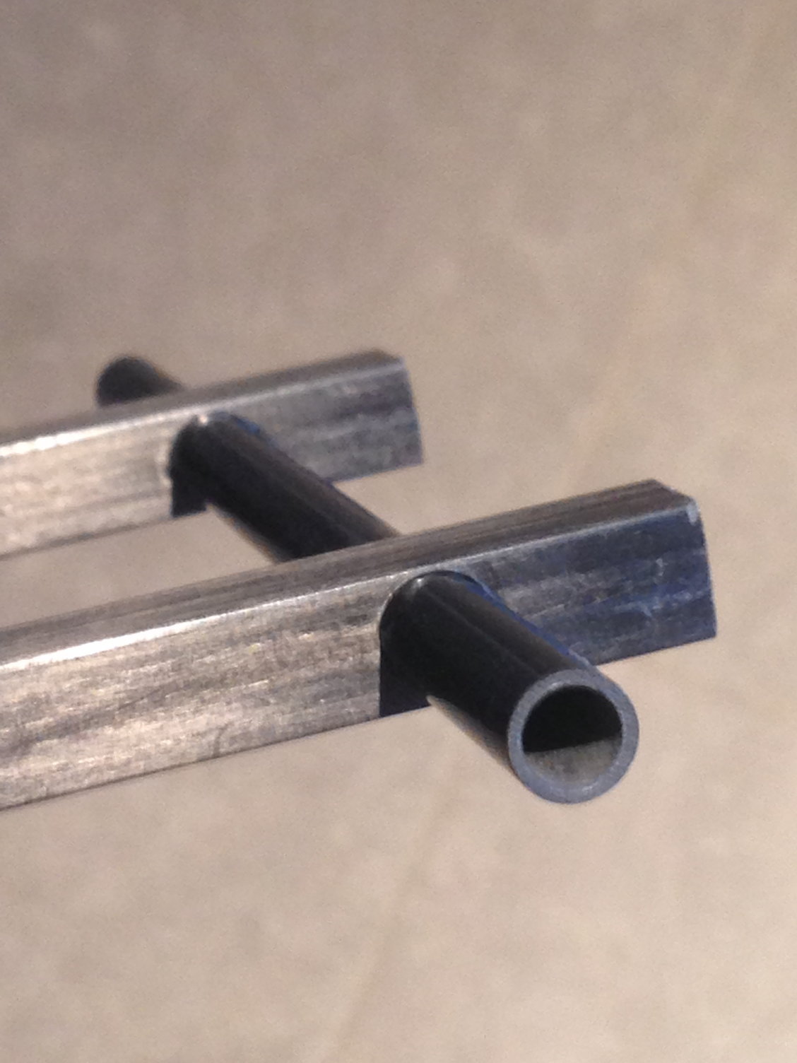
I positioned ESC and battery pack in order to install the battery tray at the right position.
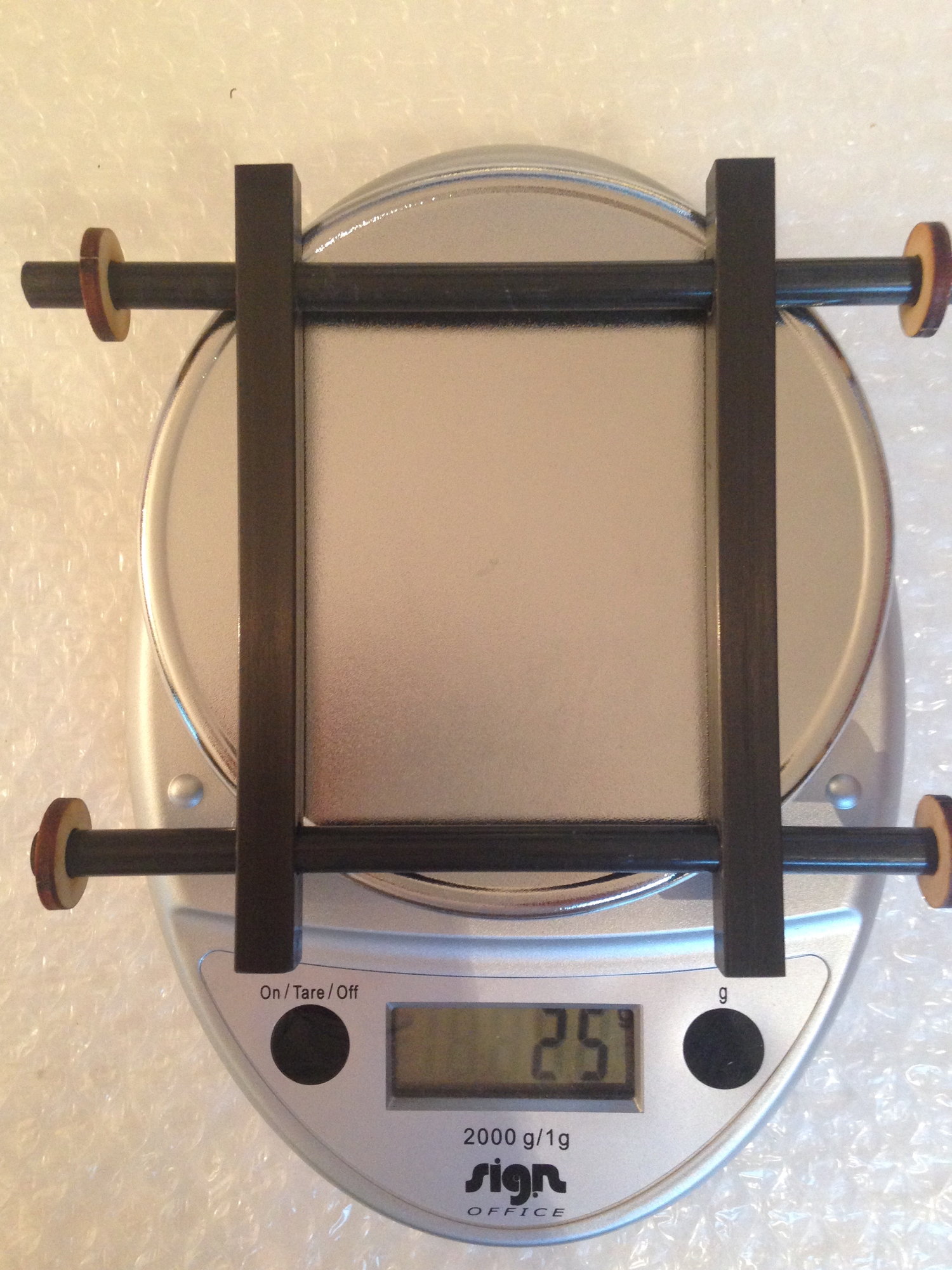
I used carbon fiber tubes, square and round, and started working on the tray.
Weight is 25 g.
I positioned ESC and battery pack in order to install the battery tray at the right position.
I used carbon fiber tubes, square and round, and started working on the tray.
Weight is 25 g.
07-14-2018 | 11:58 PM
#47
Thread Starter
My Feedback: (1)
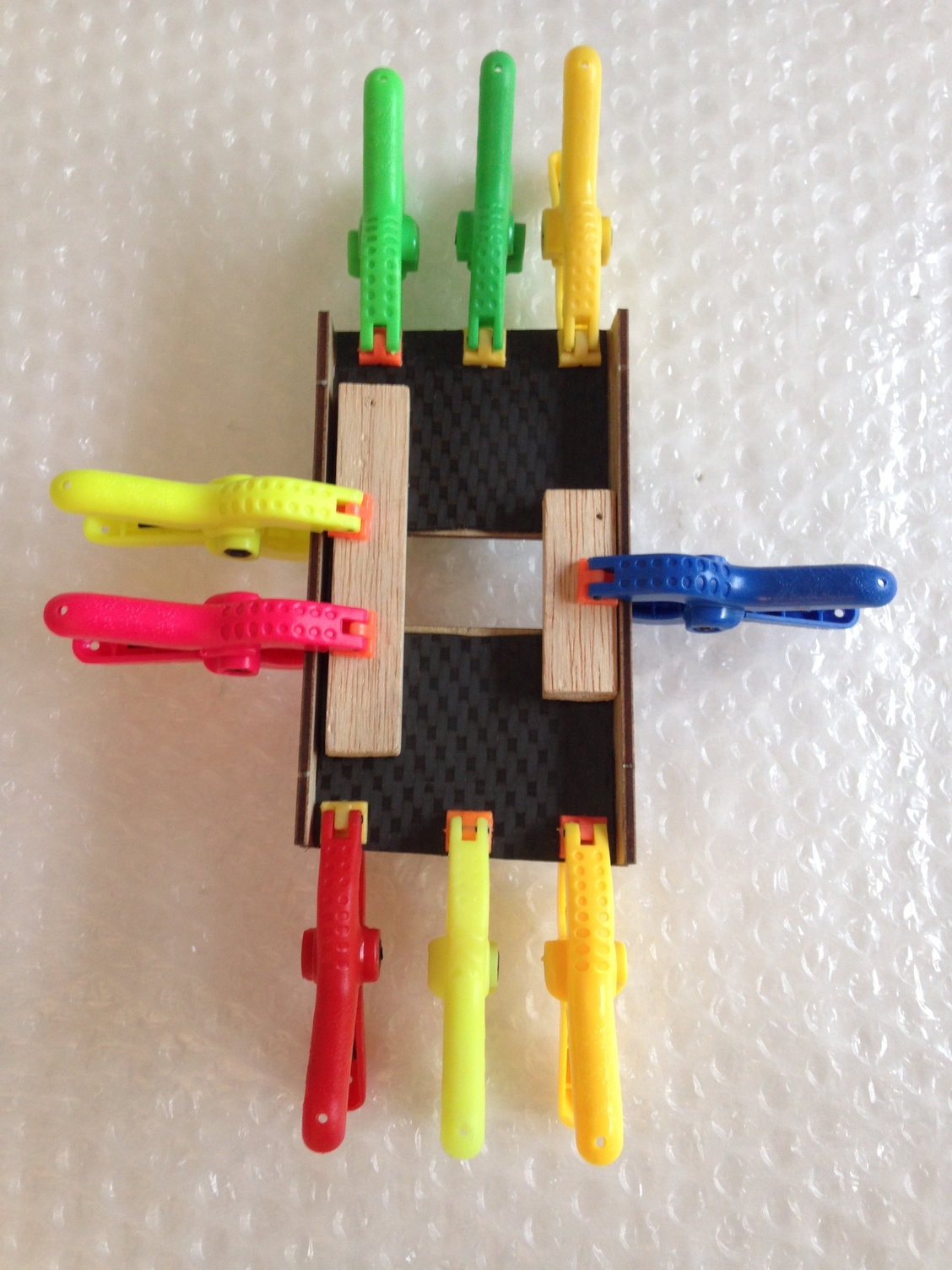
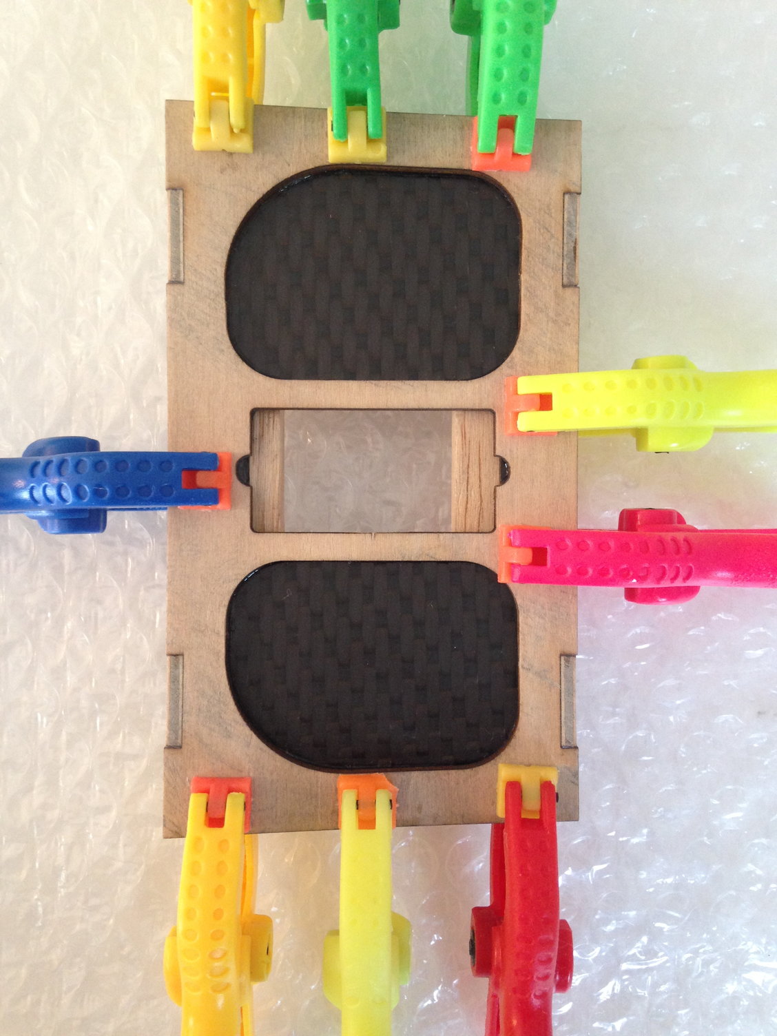
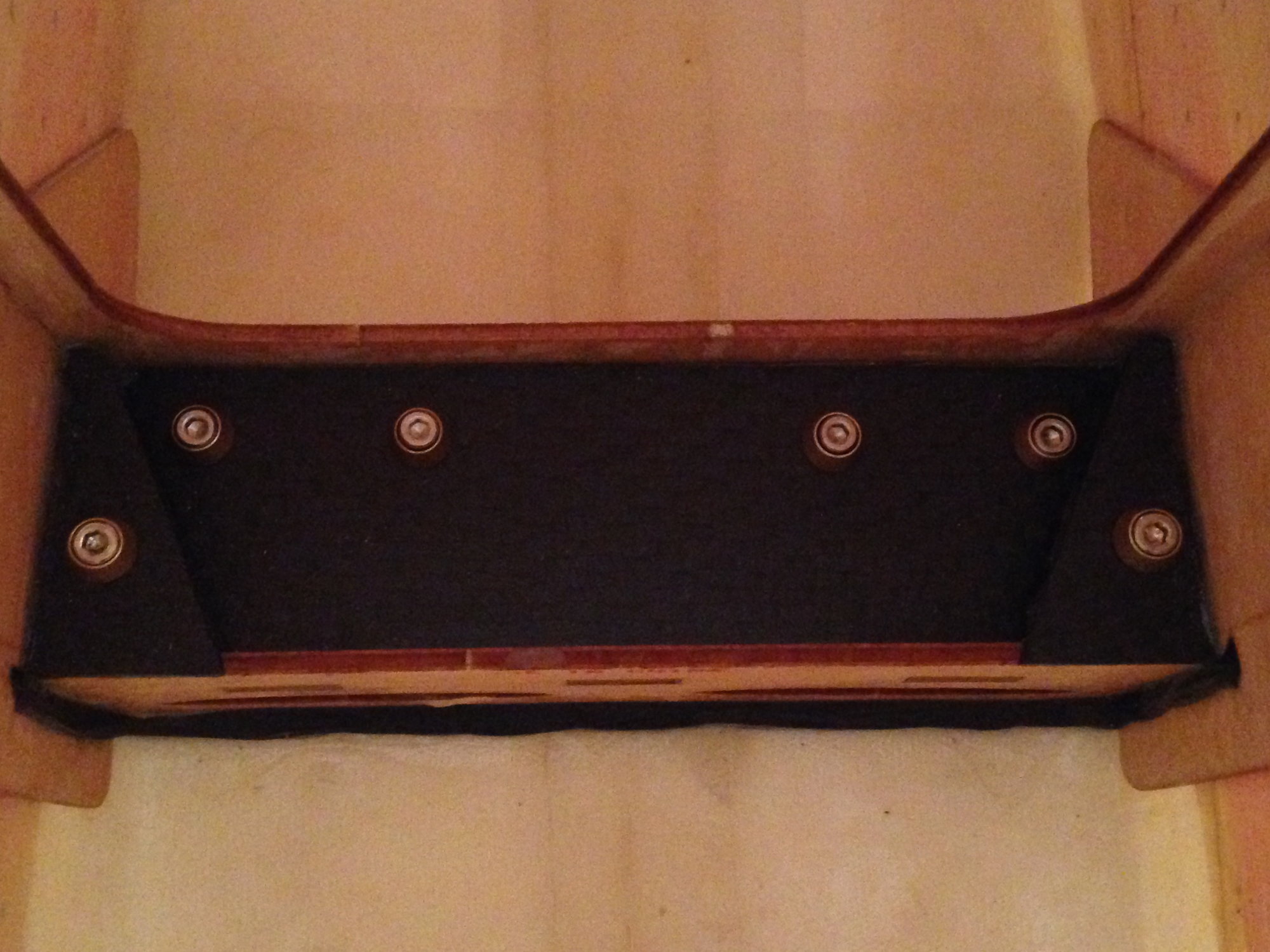
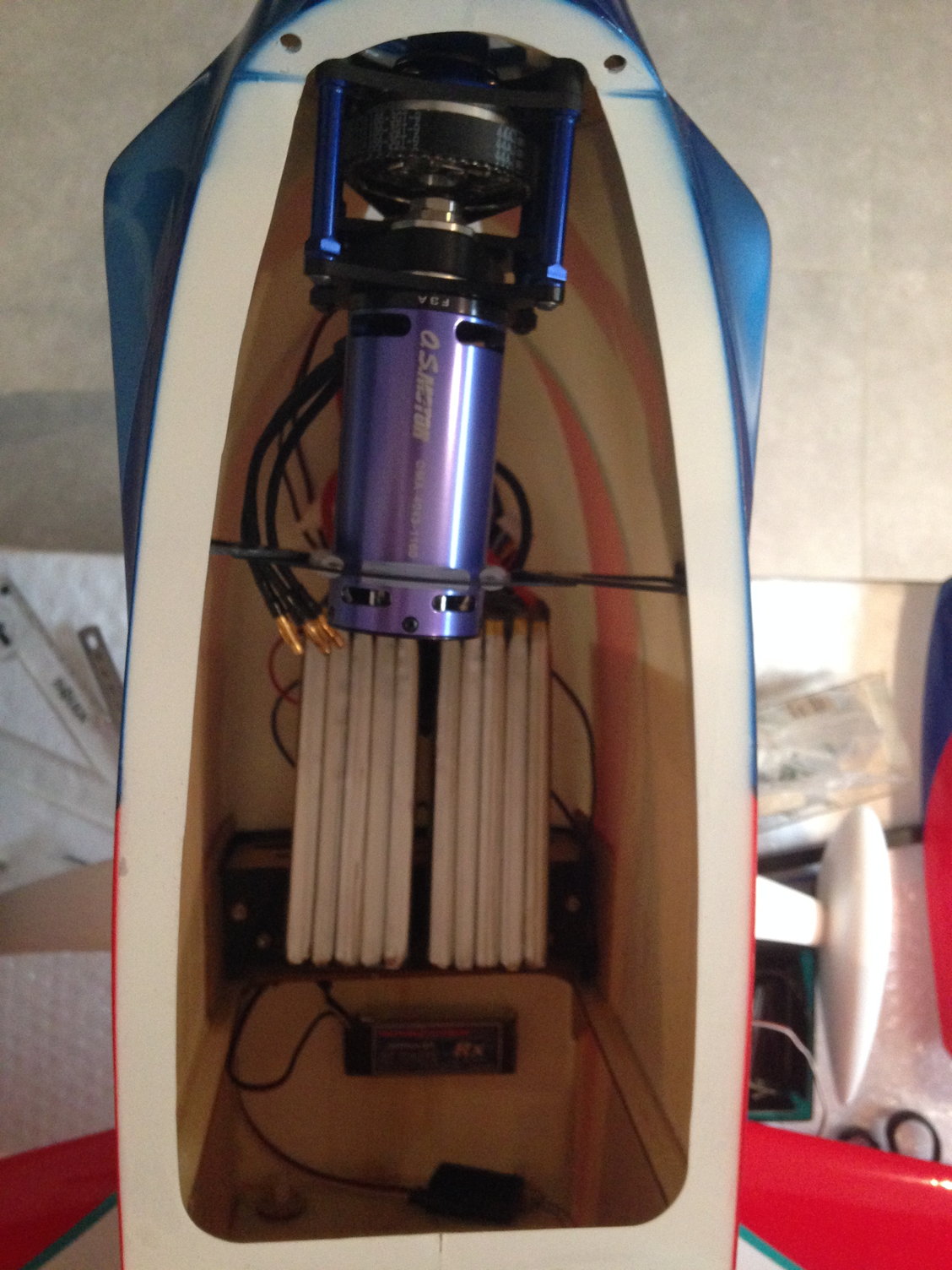
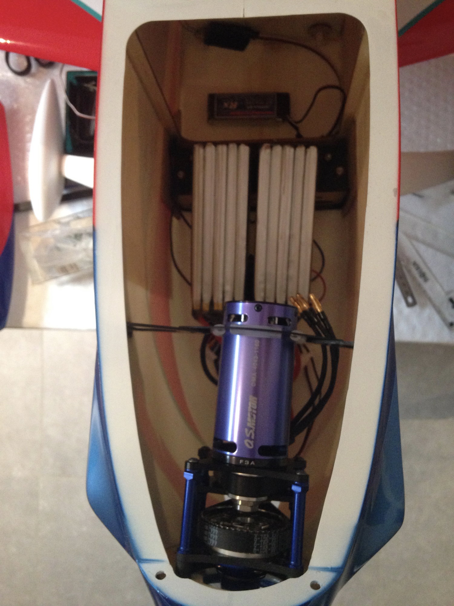
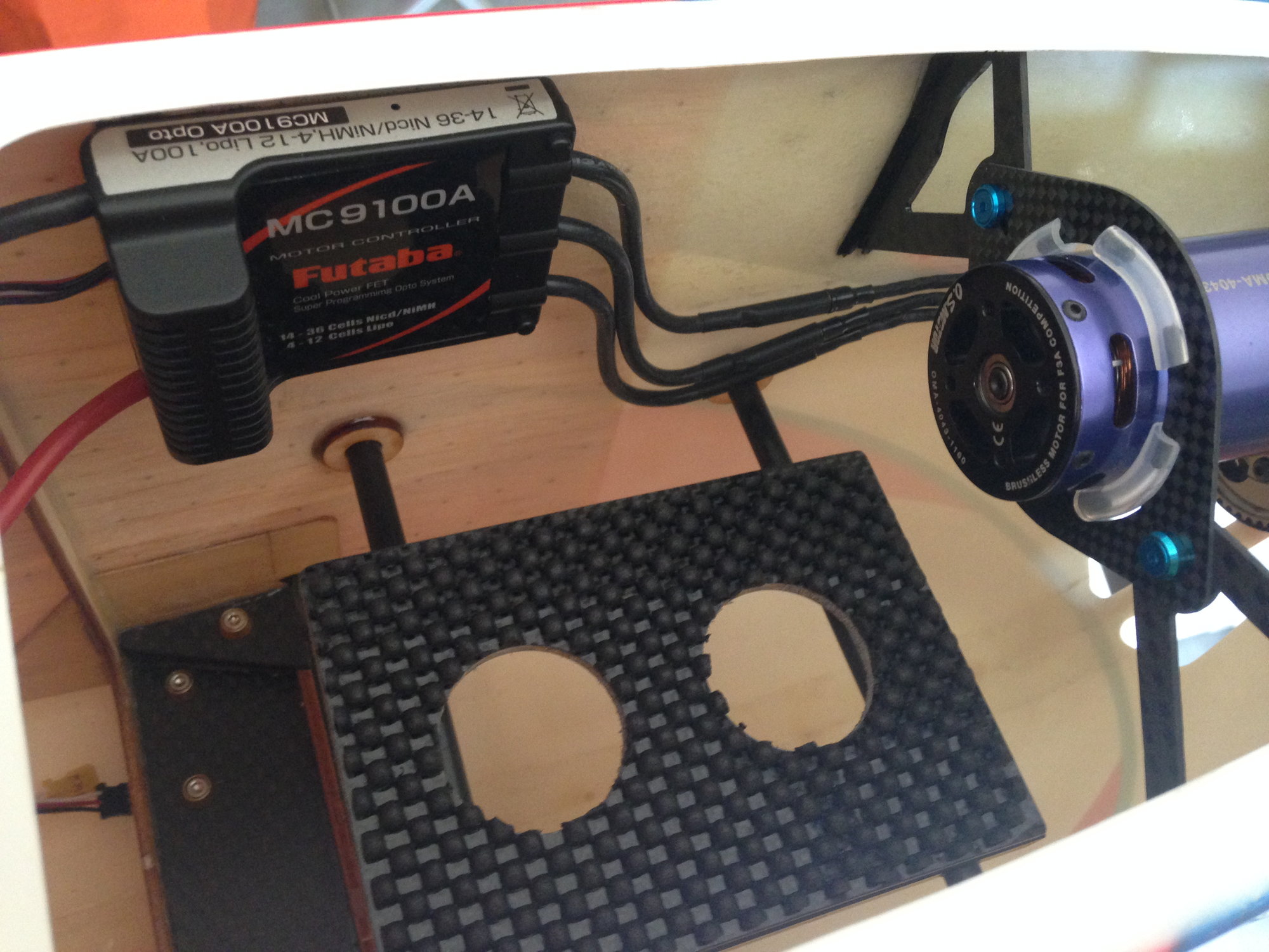
The total weight of the battery tray is 25 + 15 g for the battery support plate made of 3mm carbon balsa
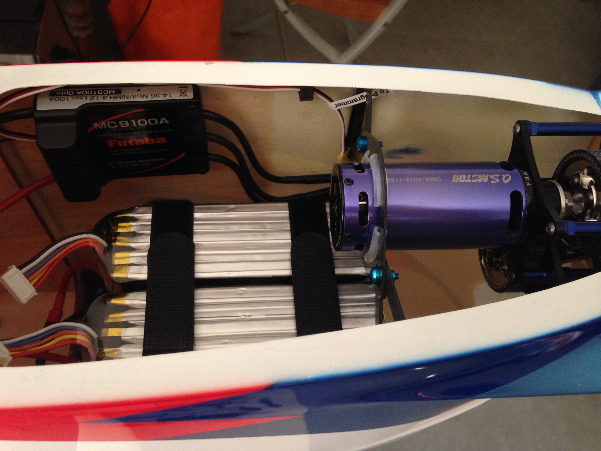
The carbon rear engine mount is secured with RS nyl-stops
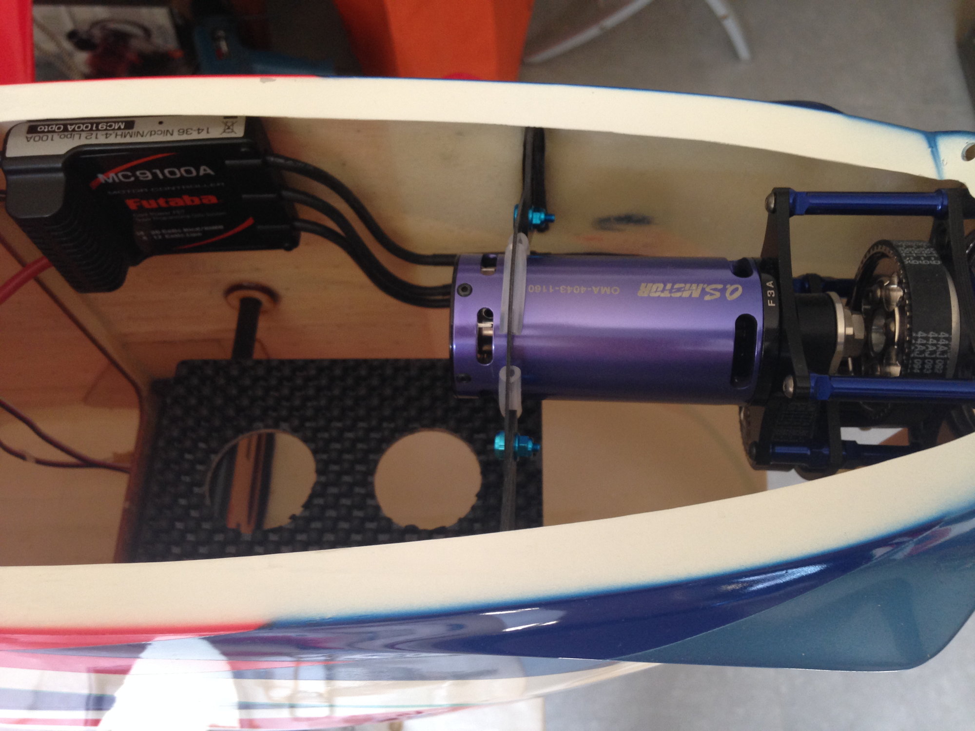
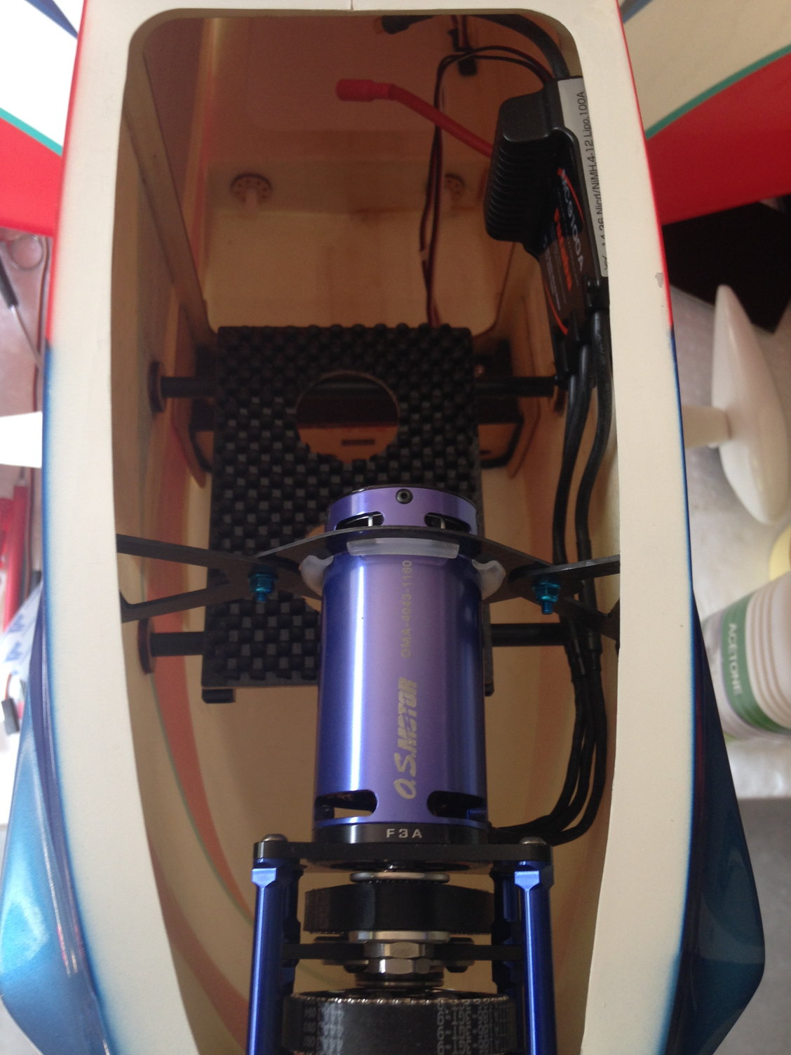
The FUTABA ESC is mounted to the fuselage side with a large - 5 cm - high quality velcro from Esprit Models
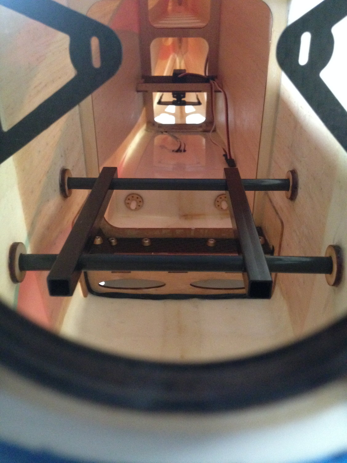
The carbon rear engine mount is secured with RS nyl-stops
The FUTABA ESC is mounted to the fuselage side with a large - 5 cm - high quality velcro from Esprit Models


 08-04-2018 | 10:15 AM
#50
Thread Starter
My Feedback: (1)
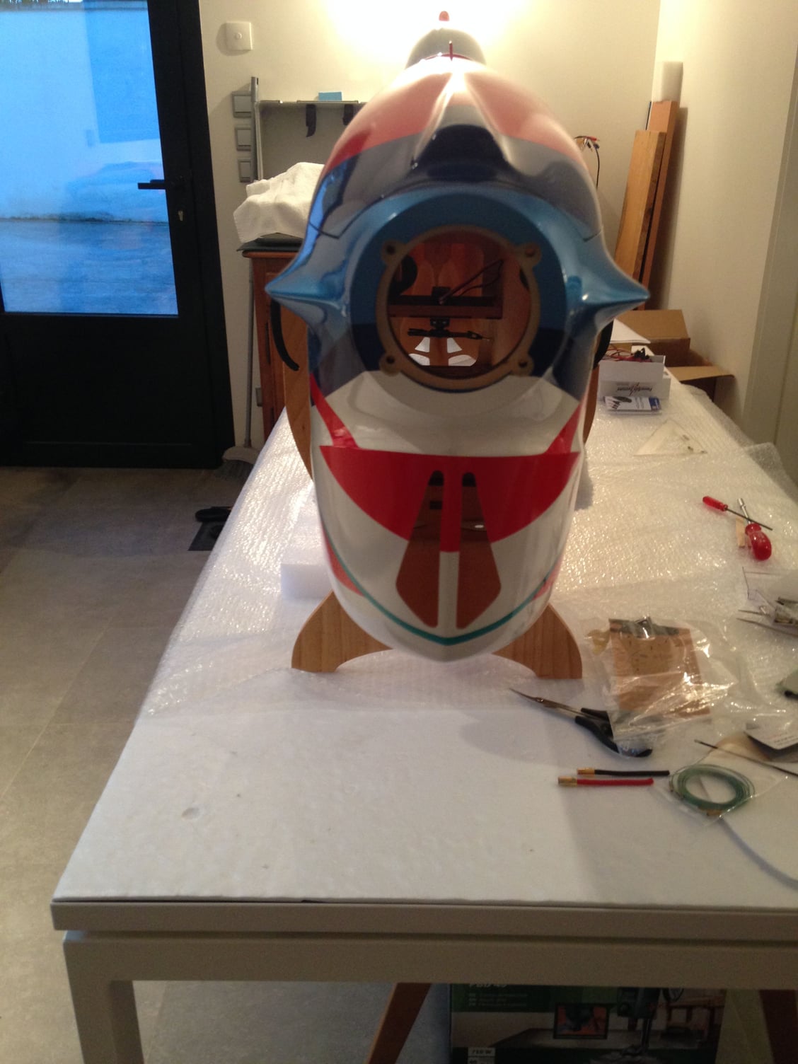
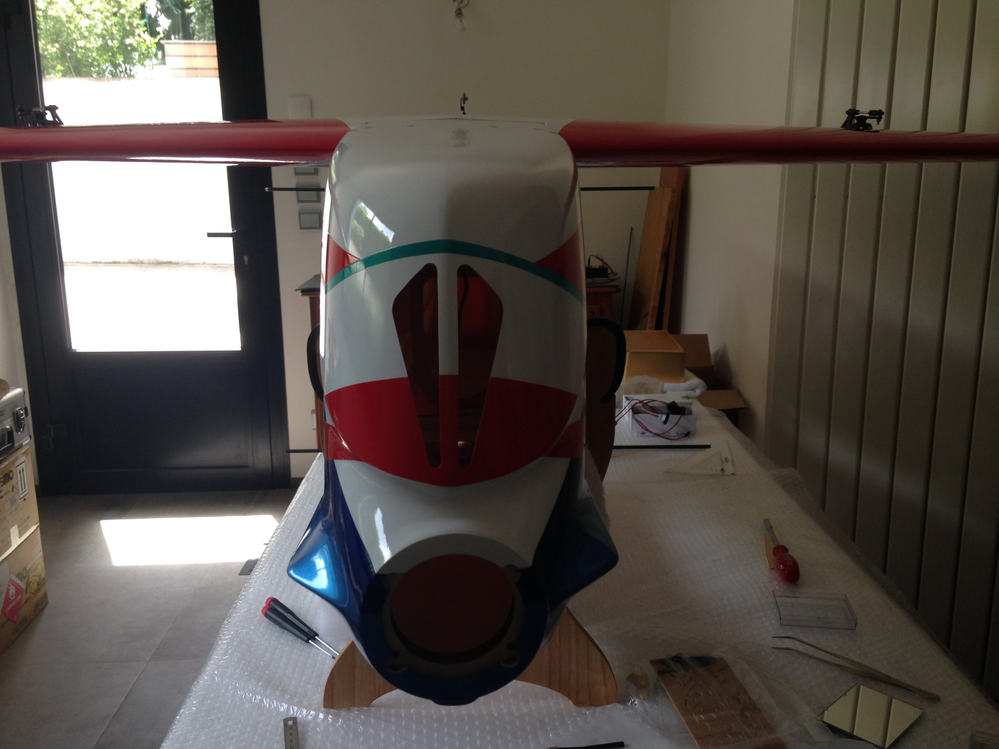
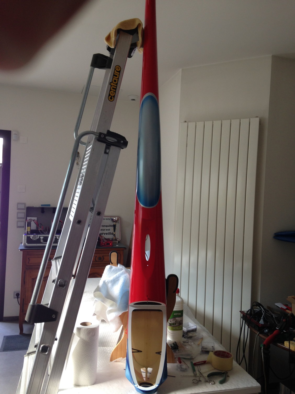
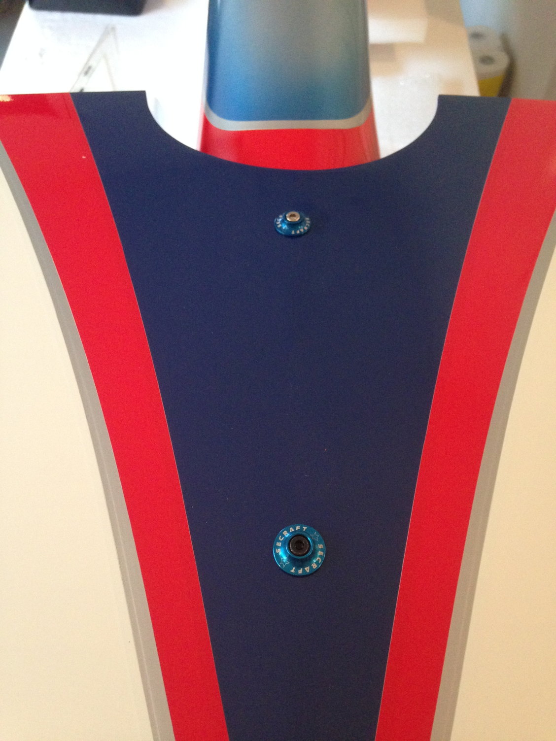
I'm just back from the 2018 EC in Belgium where I met B.J. PARK
He confirmed me that wings had no offset , what I checked on my plane.
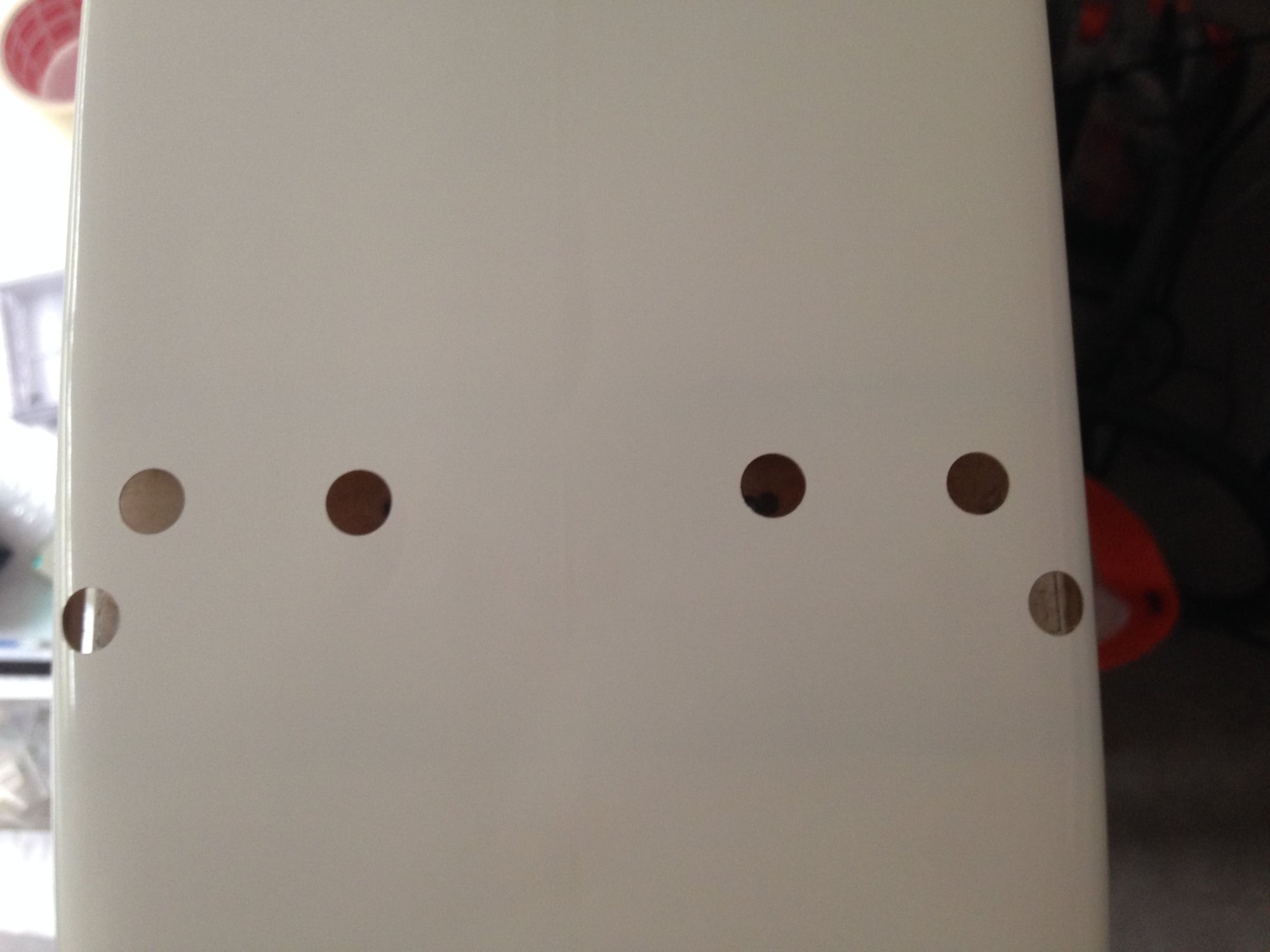
I glued blind nuts in place with 30mn epoxy.
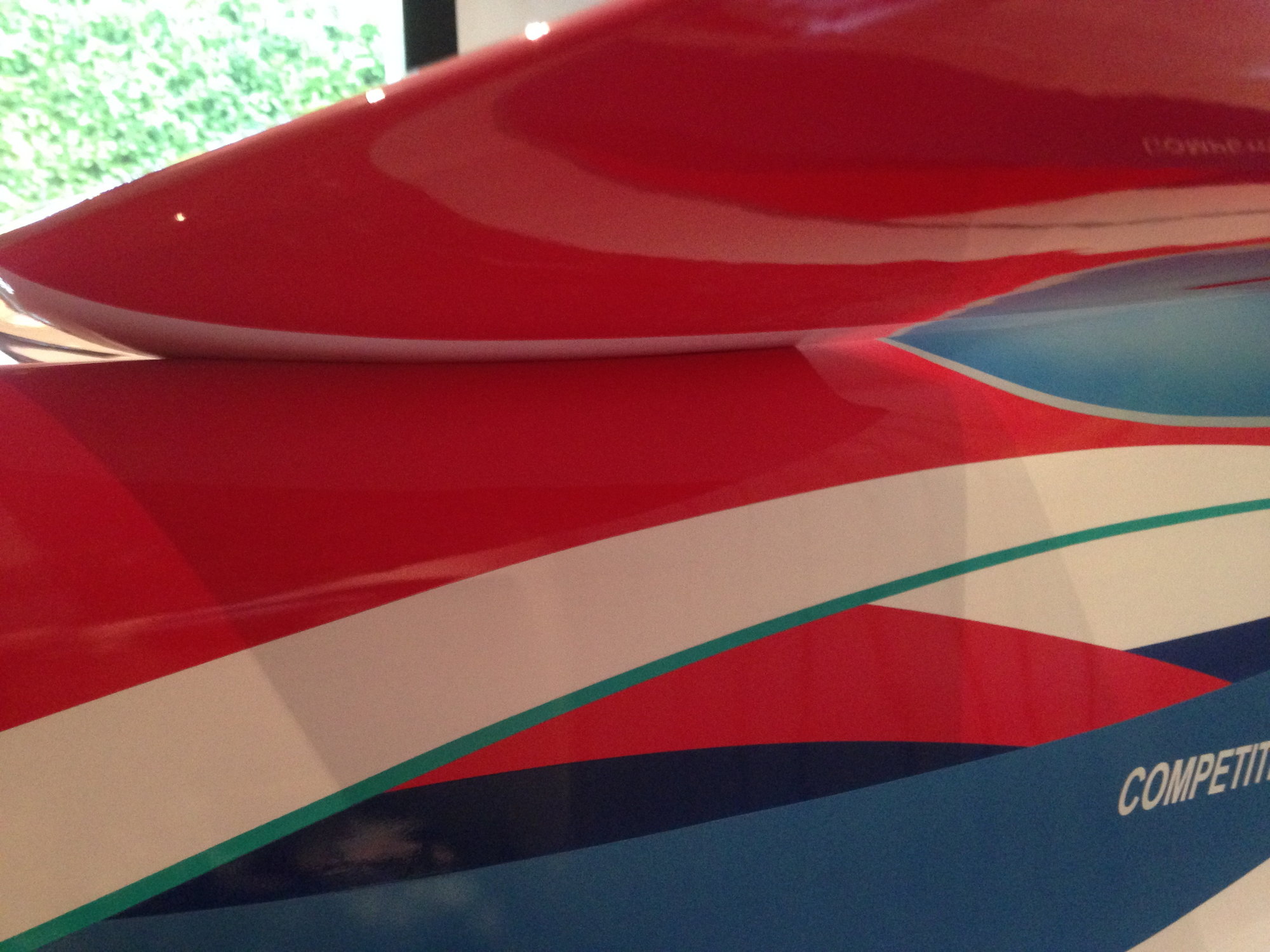
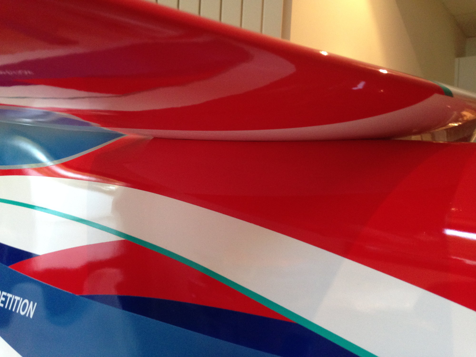
The fitting of the upper wing on the fuselage is excellent.
I have just the receiver and switch left to install, so I expect to maiden the IMMORTAL during the week.

He confirmed me that wings had no offset , what I checked on my plane.
I glued blind nuts in place with 30mn epoxy.
The fitting of the upper wing on the fuselage is excellent.
I have just the receiver and switch left to install, so I expect to maiden the IMMORTAL during the week.

