


CDI gr8flyer55
 10-06-2012, 07:27 PM
#451
Senior Member
Join Date: Nov 2005
Location: Hamburg,
PA
Posts: 805
Likes: 0
Received 0 Likes
on
0 Posts
Well folks, I knew I was going to catch hell from the wife at 11 pm for waking her up, but I just had to test the new programmed curves on my engine. Tests were 100% successful! Tracked the timing changes with a timing led and it follows exactly what I programmed..
Well done Jake !!! I'll take 10 copies..aw nevermind, I already have it..LOL
So there we have it. Cool looking software that really works! My neighbor is an electronics freak and he's gonna flip out when he see's this stuff.
I am only making one change for my preferrence, the length of time the LED is powerd is too short for a visual check of the timing in low light testing. I want to raise it a bit so it's back to normal brightness. Looking thru the code I think I found it. It must be edited into a copy of the source code, compiled with the MC8 compiler the old way, but it should solve it easily.. Unless someone else has another solution for it, this is how I'll try it.
John
 10-06-2012, 08:48 PM
#452
Senior Member
Join Date: Aug 2011
Location: Moscow,
ID
Posts: 144
Likes: 0
Received 0 Likes
on
0 Posts
I figured that might be an issue, but I didn't see any real easy way around it. I use a timing light, so the LED feature isn't that important to me.
I also thought that the rise time on the LED before the current gets flowing and it really lights up is going to make the mark show up a bit after the actual time the spark fires.
Then again the LED did seem to work better than I had expected. I just don't know how many people will use the feature and timing lights are more accurate and fairly cheap.
You could increase "Trigger_Pulse_Time" which would give the LED more time to light up. You should decrease MSD_Delay by any amount you increase the trigger pulse time. This is because MSD_Delay determines the time between pulses, so if you make the pulse longer but keep the same time between them you will be delaying the 2nd pulse by that amount.
I kind of like the idea of making a timing light with a xenon flash bulb type setup that could plug into the timer board. With a couple parts you could make one that would be accurate and bright. Junky cameras and flash units can be had at thrift stores for just a few dollars and should have all the needed parts in them. You might need a smaller or bigger cap or change some other parts around to make it able to fire/charge faster.
A project like this would fit well with the DIY spirit of the project and I bet most of us here already have the parts laying around.
On another note, if anyone finds even minor bugs or annoyances please let me know. I think we're very close to a v1.0 release, so it's time to break out the polish.
-Jake
10-07-2012, 01:22 AM
#453
Senior Member
Join Date: Aug 2011
Location: Moscow,
ID
Posts: 144
Likes: 0
Received 0 Likes
on
0 Posts
For the timer boards I think we should make a through hole version first. I think SMT will only work well if we have the whole board made and soldered in a factory. There's no reason we can't have a through hole version kit and also have some SMT versions made at some point. People who want to etch their own can still do so, and having the layout done in some sort of free program will only make things easier for them.
From what I've seen you can get 2 sided boards in prototype quantity for around $7 per square inch. That's not exactly cheap, but it shouldn't break the bank either. I'm sure it can be done a lot cheaper in quantity with the boards panelized. Some places seem to have rules about internal routing or charge extra, so it will probably take some looking around to find the best place for medium quantity panelized runs.
All places take gerber files, which is the actual file that can be fed into the machines. But quite a few will take Eagle files also. That seems like the easiest way to me IMHO. With an Eagle file they have everything on the project and can make changes to it and validate that it will turn out right. With just a gerber you can have mistakes that will make the boards turn out wrong, and they usually won't refund problems like that. I'd just as soon have the board house make sure it will turn out like the Eagle file shows.
Eagle can be a pain and really piss you off at times. Some parts seem crappy and broken, but it actually does work well once you learn how to do things with it. All the functionality is there, it's just sometimes hard to figure out their odd interface. Once you learn it, then it seems a lot easier.
I'm using an iCP07 board connected to the timer board for most of my programming. That board seems pretty decent, so it might be a good place to start for figuring out our timer board design. I know that the ICP header setup works on it and all the pins are exposed.
You can find it here...
http://www.piccircuit.com/shop/pic-d...oard-tiny.html
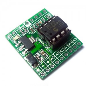
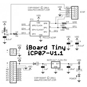
We probably don't need the voltage regulator, especially since a UBEC is only around $3-4 from hobbyking. I'm not good enough at EE to figure out what other components could be tossed, but it might not hurt to keep some of the power filtering. Looks like they use 1nF, 0.1uF, 1uF, and 10uF caps for filtering. Other than that there's just a couple resistors and a diode for polarity protection.
There really isn't much to the timer board. We mainly just have to figure out the routing so that all the pins are exposed and organized in a way that suits our connection setup. I'd also like to have a temp sensor, so one of the pins should be arranged next to a +5V pin.
Another idea would be to have a voltage divider on one of the pins so that we could read battery voltage levels. Whatever voltage battery packs people are using needs to be divided down into 0-5V so that the ADC on the PIC can measure it. Hopefully there's a range that will give decent resolution and still cover all the voltages people want to use. The PIC has a 10-bit ADC, so that 0-5V range is split into 1024 possible values.
I don't know what you guys think about monitoring the battery voltage, but it's one of the first things I think about with battery operated devices. I don't like them dying by surprise, and it's not good if it drains them until they're ruined either.
I think it would also be nice to have some sort of beeper or buzzer on the board also, or maybe an optional connection for one. Communicating with simple devices is always tough, but I usually seem to find beeps easier to understand than flashing lights. Then again, engine noise might make it kind of difficult to use beeps. Maybe it can have a beeper and light tied to the same output pin?
Anyways, that's just some things to keep in mind for the future. Since we're making these all one at a time at the moment, it wouldn't hurt to have multiple designs also.
-Jake
From what I've seen you can get 2 sided boards in prototype quantity for around $7 per square inch. That's not exactly cheap, but it shouldn't break the bank either. I'm sure it can be done a lot cheaper in quantity with the boards panelized. Some places seem to have rules about internal routing or charge extra, so it will probably take some looking around to find the best place for medium quantity panelized runs.
All places take gerber files, which is the actual file that can be fed into the machines. But quite a few will take Eagle files also. That seems like the easiest way to me IMHO. With an Eagle file they have everything on the project and can make changes to it and validate that it will turn out right. With just a gerber you can have mistakes that will make the boards turn out wrong, and they usually won't refund problems like that. I'd just as soon have the board house make sure it will turn out like the Eagle file shows.
Eagle can be a pain and really piss you off at times. Some parts seem crappy and broken, but it actually does work well once you learn how to do things with it. All the functionality is there, it's just sometimes hard to figure out their odd interface. Once you learn it, then it seems a lot easier.
I'm using an iCP07 board connected to the timer board for most of my programming. That board seems pretty decent, so it might be a good place to start for figuring out our timer board design. I know that the ICP header setup works on it and all the pins are exposed.
You can find it here...
http://www.piccircuit.com/shop/pic-d...oard-tiny.html
We probably don't need the voltage regulator, especially since a UBEC is only around $3-4 from hobbyking. I'm not good enough at EE to figure out what other components could be tossed, but it might not hurt to keep some of the power filtering. Looks like they use 1nF, 0.1uF, 1uF, and 10uF caps for filtering. Other than that there's just a couple resistors and a diode for polarity protection.
There really isn't much to the timer board. We mainly just have to figure out the routing so that all the pins are exposed and organized in a way that suits our connection setup. I'd also like to have a temp sensor, so one of the pins should be arranged next to a +5V pin.
Another idea would be to have a voltage divider on one of the pins so that we could read battery voltage levels. Whatever voltage battery packs people are using needs to be divided down into 0-5V so that the ADC on the PIC can measure it. Hopefully there's a range that will give decent resolution and still cover all the voltages people want to use. The PIC has a 10-bit ADC, so that 0-5V range is split into 1024 possible values.
I don't know what you guys think about monitoring the battery voltage, but it's one of the first things I think about with battery operated devices. I don't like them dying by surprise, and it's not good if it drains them until they're ruined either.
I think it would also be nice to have some sort of beeper or buzzer on the board also, or maybe an optional connection for one. Communicating with simple devices is always tough, but I usually seem to find beeps easier to understand than flashing lights. Then again, engine noise might make it kind of difficult to use beeps. Maybe it can have a beeper and light tied to the same output pin?
Anyways, that's just some things to keep in mind for the future. Since we're making these all one at a time at the moment, it wouldn't hurt to have multiple designs also.
-Jake
10-07-2012, 01:27 AM
#454
Senior Member
Ok So I try to build the latest beta and I get some error messages.
Error [254] C:\Users\Charlie\Desktop\Jakestew\New folder\CDI-2012_12F683_v0.98b6.c; 230.0 undefined variable: "init"
(908) exit status = 1
What do I need to do? I don't really have time to trouble shoot this.
Error [254] C:\Users\Charlie\Desktop\Jakestew\New folder\CDI-2012_12F683_v0.98b6.c; 230.0 undefined variable: "init"
(908) exit status = 1
What do I need to do? I don't really have time to trouble shoot this.
10-07-2012, 02:16 AM
#455
Senior Member
Jake that is a nice little board. Its going to need a few more parts though. The reg. is pretty much needed as people will be using the ignitions above 5 volts. its already there so why not keep it.
10-07-2012, 02:54 AM
#456
Senior Member

Join Date: Jul 2010
Location: Alkmaar, NETHERLANDS
Posts: 404
Likes: 0
Received 0 Likes
on
0 Posts
I've a question.......are all of our models so small there is no place for a normal PCB ?
This opensource DIY (Do It Yourself) project will be a BIY (Buy It Yourself) project.
Most people who fly petrol engines and big planes, are older people with working hands.
They can't make a SMD PCB, with some luck they can see the parts but not wat kind of part it is.
You need also special equipment for SMD, with a normal soldering iron you will burn the parts.
If you decided to use SMD, you must be deliver a (BIY) complete build CDI, no kit.
And now we are coming to the cost, make SMD PCB will be expencive - assembly the SMD to the PCB will be expencive - buy a complete SMD-CDI will be expencive.
Why people will buy a expencive CDI......they aren't waiting for a other expencive CDI.
They want to save money to build a CDI by them self, and learn to solder and electronics.
And most of all they are very happy if the CDI they have make by them self it is working.
Thats also why all of my projects are opensource, I like it if I can people make intrersted into electronics and modelbuilding.
Please if you want to make this project commercal, stop right now to devolpe it.
Build a new CDI with all the options you want to have, make a company by your own with all the people who help to devolpe the new CDI, and sell it the highest bidder.
I promise to make a PCB (opensource) but only for normal components, so everybody can build the CDI.
10-07-2012, 03:20 AM
#457
Senior Member
Hi Rob,
I agree with you 100%. If its open source then it seems that all the stuff ie software, schematics, board layout is offered here free to anyone want to build there own. IF you start talking of commercial boards and SMD and kits then it is no longer a DIY project, but it starts competing with other commercial units. Then if kits are offered who will warranty and help the end user with any problems?
I agree with you 100%. If its open source then it seems that all the stuff ie software, schematics, board layout is offered here free to anyone want to build there own. IF you start talking of commercial boards and SMD and kits then it is no longer a DIY project, but it starts competing with other commercial units. Then if kits are offered who will warranty and help the end user with any problems?
10-07-2012, 04:59 AM
#458
Senior Member
Join Date: Jul 2010
Location: Alkmaar, NETHERLANDS
Posts: 404
Likes: 0
Received 0 Likes
on
0 Posts
You need a cheap / small / SMD timerboard with a lot of options ?
For only 12.97 $US you can have a very nice board ready to use.
https://www.olimex.com/Products/Duino/PIC32/
For only 12.97 $US you can have a very nice board ready to use.
https://www.olimex.com/Products/Duino/PIC32/
10-07-2012, 06:13 AM
#459
Senior Member
Join Date: Nov 2005
Location: Hamburg,
PA
Posts: 805
Likes: 0
Received 0 Likes
on
0 Posts
Rob, I worked around the led problem last night by using your stroboscope timing light on the sparkplug wire. It worked well on my test engine that does not have a braided-shielded sparkplug wire. Tried it on a shielded wire but couldn't get enough signal to trigger it reliably. I was thinking of a direct connect to the led output on the timer board as another small optional project to make it work. Is there a way to not use the antenna loop but hook directly to the stroboscope to get a positive reliable trigger signal?
If that can be done, there you have a perfect, small bright DIY timing light for this project!
I figured if we needed to go this route, using the now shorter pulse signal would be a good enough signal to drive it.
About a year ago, I made a very simple static timing light (engine not running) , to do initial ignitial engine timing setup. I also still use it today. It plugs inline on the hall sensor cable between the sensor and ignition so no external power source is needed. It uses the sensor signal to light a led when engine would normally have the plug fire but in fact steals the signal, and does not allow the ignition to actually fire, a sort of safety feature as a side benefit.
If you look back thru the other forum thread in the gallery, you will find the pictures along with the schematic for it, a very simple project built in a few minutes time.
Just some ideas I had last night, to solve the led brightness problem without altering a single thing in Jakes powerful programming. It is just a few work around ideas that are add-ons to the project. Think of them as DIY options for the best project presented in years for ignitions.
John
10-07-2012, 07:17 AM
#460
Senior Member
Join Date: Jul 2010
Location: Alkmaar, NETHERLANDS
Posts: 404
Likes: 0
Received 0 Likes
on
0 Posts
John, I use this one http://www.electronics.gompy.net/strobelight/ by myself.
It's usable untill ~9,000 rpm by changing a capacitor.
I also use it with the sheelded cable of my bike without loosing pulses.
But I have to place the crocedilclip near the coil and not near the candle.
The clip will pickup the pulses from the coil and it looks a very good signal.
I also expirement with a xenontube from a disposal camera and connectected to the flash output of the PIC.
I note with daylight the LED-light is not enough to read the degree disk wel.
If you want optimize the LED-light fast, buy a cheap LED-flashlight with a good lens.
10-07-2012, 08:04 AM
#461
Senior Member
Join Date: Nov 2005
Location: Hamburg,
PA
Posts: 805
Likes: 0
Received 0 Likes
on
0 Posts
Rob, I too have experimented with different ways to connect it for a good strong positive signal. This is what I am trying to figure out. We need an interface connection to directly plug in for the signal, full strength to make it bright and reliable. A cheap led flashlight is a good light source which I have tried and it works perfectly.
I have many ways to do what need but involve complicated hookups. We just need a simple, easy to use, foolproof, system that anyone can have success with. A users tool, not an experimenters nightmare.
We could make it an accessory item. That is the add-on approach which will work.
One more item we need is the direct rpm readout to accurately check rpm with respect to timing. I have my own way of doing this with an optical tach pointed at the prop. Also had worked by pointing it at the timer's led and reading it, multiplying the reading by 2 (my tach is set for a 2 blade prop- 2 interuptions per revolution). This would be fine except now with the led on the board being so dim, doesn't work at all. Maybe using the RCExl inline tach is the solution there too. Just a thought.
John
10-07-2012, 10:22 AM
#463
Senior Member
Join Date: Nov 2005
Location: Hamburg,
PA
Posts: 805
Likes: 0
Received 0 Likes
on
0 Posts
Jake, I just posted a short video of a cold start but primed engine to test the newest 9.6 version software and one of my good curves. Seems to have no bad habits so far. Benefits are a one flip start, smooth idle, and good top rpms.
You wanted proof that it works on an engine, well here it is.
Take a look, hope the link works.
John
You wanted proof that it works on an engine, well here it is.
Take a look, hope the link works.
John
10-07-2012, 12:12 PM
#468
Senior Member
Join Date: Aug 2011
Location: Moscow,
ID
Posts: 144
Likes: 0
Received 0 Likes
on
0 Posts
Good catch Charlie. The copy code to clipboard macro was leaving a few lines off the end.
I swear I checked this, but somehow it must have gotten screwed up. I just fixed this and uploaded the fixed file to the website. No version change, but it should work now.
Anyone who downloaded the spreadsheet already should download a new copy or just remember that the copy code button leaves some lines off the end. The code is all there, but the macro just doesn't copy all of it.
Remember also that the copy code button does not put your curves into the code, it just copies the default code into the clipboard. You will have to copy curve 1 and 2 and paste them into the code. There's only two lines to change now, so I didn't want to have to mess with the macros every time there's a code change.
-Jake
 10-07-2012, 12:25 PM
#470
Senior Member
Join Date: Nov 2005
Location: Hamburg,
PA
Posts: 805
Likes: 0
Received 0 Likes
on
0 Posts
Thanks Adrian !!
My Iphone is giving me alot of problems right now.. Need to do an upgrade in software today for it, till then, Adrian has helped me out once again.. Thank You !!
John
My Iphone is giving me alot of problems right now.. Need to do an upgrade in software today for it, till then, Adrian has helped me out once again.. Thank You !!
John
10-07-2012, 12:30 PM
#471
Senior Member
Join Date: Aug 2011
Location: Moscow,
ID
Posts: 144
Likes: 0
Received 0 Likes
on
0 Posts
[youtube]http://www.youtube.com/watch?v=0wjS7lfg6-U[/youtube]
It works if you use the "youtube" in brackets BB code.
Very awesome to see this vid! One flip cold start is amazing!
Makes me think of the last time I started my string trimmer. I pulled until my arm was sore then got pissed and finally started pulling it really fast, and it finally started.
-Jake
It works if you use the "youtube" in brackets BB code.
Very awesome to see this vid! One flip cold start is amazing!
Makes me think of the last time I started my string trimmer. I pulled until my arm was sore then got pissed and finally started pulling it really fast, and it finally started.
-Jake
10-07-2012, 12:31 PM
#472
Senior Member
Join Date: Aug 2011
Location: Moscow,
ID
Posts: 144
Likes: 0
Received 0 Likes
on
0 Posts
[youtube]http://www.youtube.com/watch?v=0wjS7lfg6-U[/youtube]
It works if you use the "youtube" in brackets BB code.
Very awesome to see this vid! One flip cold start is amazing!
Makes me think of the last time I started my string trimmer. I pulled until my arm was sore then got pissed and finally started pulling it really fast, and it finally started.
-Jake
It works if you use the "youtube" in brackets BB code.
Very awesome to see this vid! One flip cold start is amazing!
Makes me think of the last time I started my string trimmer. I pulled until my arm was sore then got pissed and finally started pulling it really fast, and it finally started.
-Jake
10-07-2012, 12:46 PM
#473
Senior Member
Thanks Jake,
Nice video John.
So Jake after the curve is changed One has to copy and paste the new curve values to the code? Thats fine. I was not sure of the tables updated automatically when the curves are changed.
Thanks for fixing the other problem.
Nice video John.
So Jake after the curve is changed One has to copy and paste the new curve values to the code? Thats fine. I was not sure of the tables updated automatically when the curves are changed.
Thanks for fixing the other problem.
10-07-2012, 01:02 PM
#474
Senior Member
Ok now that I can get it to compile I have another problem. It just sits there like a bump on a log. I get no sparky sparky from the ignition. When in the development board I also get no reaction from toggling the input pin. I am going to sim it in MPLAB and see whats going on.
10-07-2012, 01:07 PM
#475
Senior Member
Join Date: Nov 2005
Location: Hamburg,
PA
Posts: 805
Likes: 0
Received 0 Likes
on
0 Posts
Charlie, I just emailed my Excel sheet with my test 9 curves in it for him to post as a basic generic starting point.. Would you like a copy and the resulting hex file to try out?
John
John