


CDI gr8flyer55
 03-31-2013, 08:32 PM
#1101

Join Date: Nov 2004
Location: PortoNo state, PORTUGAL
Posts: 24
Received 0 Likes
on
0 Posts
Good Evening Mr Rob (Gompy)
Have you got idea , when it will be ready your package?
It is adaptable to small motorbikes? I Would like to buy to test on my scooter one version of yours.
Please could you email me : [email protected]
Best Regards
Nuno
Have you got idea , when it will be ready your package?
It is adaptable to small motorbikes? I Would like to buy to test on my scooter one version of yours.
Please could you email me : [email protected]
Best Regards
Nuno
 04-01-2013, 10:34 AM
#1102
Junior Member
Join Date: Aug 2010
Location: Szeged, HUNGARY
Posts: 11
Likes: 0
Received 0 Likes
on
0 Posts
hi Guys!
I'm back on the forum, after a while (i'm the guy who also made a programable cdi with real time monitoring and on the fly programing)
I'm back on the forum, after a while
(i'm the guy who also made a programable cdi with real time monitoring and on the fly programing)I see that you were making a working project, really thats nice.
I have only one question, is there a version for inductive pickup? I want to try it on my scooter.
04-05-2013, 05:28 PM
#1103
Junior Member
Join Date: Mar 2013
Location: pacitanjawa timur, INDONESIA
Posts: 3
Likes: 0
Received 0 Likes
on
0 Posts
dear gompy,
ok i know. can you send me email about detail how to ship to my country.?
do you have paypal account?
this is my email : [email protected]
ok i know. can you send me email about detail how to ship to my country.?
do you have paypal account?
this is my email : [email protected]
04-21-2013, 06:56 PM
#1104
Senior Member
Join Date: Feb 2010
Location: szarvas, HUNGARY
Posts: 133
Likes: 0
Received 0 Likes
on
0 Posts
Hi Gompy
Congratulations Gompy.
I'm not competing with you.
I'm looking for a good, ignition delay curves.
[youtube]http://youtu.be/wBt48RQyMMU[/youtube]
youtu.be/wBt48RQyMMU
Regards nyemi
Congratulations Gompy.
I'm not competing with you.
I'm looking for a good, ignition delay curves.
[youtube]http://youtu.be/wBt48RQyMMU[/youtube]
youtu.be/wBt48RQyMMU
Regards nyemi
 04-26-2013, 08:38 PM
#1106
Senior Member
Join Date: Feb 2010
Location: szarvas, HUNGARY
Posts: 133
Likes: 0
Received 0 Likes
on
0 Posts
Hi Gompy
You made codes, engine practical operation, a video?
I'm very curious, 2t engine.
Because the proof of the pudding is in the eating.
Thank you.
Regards nyemi
You made codes, engine practical operation, a video?
I'm very curious, 2t engine.
Because the proof of the pudding is in the eating.
Thank you.
Regards nyemi
04-27-2013, 03:03 AM
#1107
Senior Member

Join Date: Jul 2010
Location: Alkmaar, NETHERLANDS
Posts: 404
Likes: 0
Received 0 Likes
on
0 Posts
We have to test it on our own bikes and modelengines.
When we are 100% ready, we will announce everyone.
But first I have to make a powersupply out of the bike to feed the low (5V) Voltage part.
NO, we don't make a fast run...this time we deliver a ready to use product without bugs.
When we are 100% ready, we will announce everyone.
But first I have to make a powersupply out of the bike to feed the low (5V) Voltage part.
NO, we don't make a fast run...this time we deliver a ready to use product without bugs.
 08-28-2013, 07:37 PM
#1110
Junior Member
Join Date: Aug 2013
Posts: 5
Likes: 0
Received 0 Likes
on
0 Posts
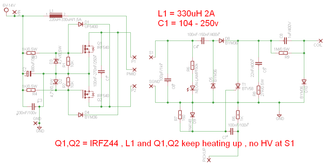
i' built nyemi ZVS , but i got some problem , anyone help ? i' tried to contact nyemi via google , but he' not there.
only the HV part , Q1 Q2 are IRFZ44 , L1 330uH,2A , C1 104-250v , Q1 Q2 , L1 keep heating up , no HV. supply voltage 5v and 12v.
all diode using bym26E ( rating 1000v , 2.3A) values in schematic for easy component placing.
only the HV part , Q1 Q2 are IRFZ44 , L1 330uH,2A , C1 104-250v , Q1 Q2 , L1 keep heating up , no HV. supply voltage 5v and 12v.
all diode using bym26E ( rating 1000v , 2.3A) values in schematic for easy component placing.
08-29-2013, 02:17 PM
#1111
Member

Join Date: Jul 2013
Location: near Malone, NY
Posts: 35
Likes: 0
Received 0 Likes
on
0 Posts
Looks like you've got Q1+Q2 turned full on. Are you sure you're diagram is correct? You have two voltage dividers R3/R1 and R4/R2 feeding DC to Q1,Q2 and you've grounded the output of Q1, Q2, sure as hell they're going to get hot.
I assume P1,P2 are supposed to be the primary windings?
If you're feeding this with DC, your primary coil will act like a dead short feeding Q1+Q2 with full supply voltage
If you put a momentary switch on the power supply, do you get a pop at the output?
I assume P1,P2 are supposed to be the primary windings?
If you're feeding this with DC, your primary coil will act like a dead short feeding Q1+Q2 with full supply voltage
If you put a momentary switch on the power supply, do you get a pop at the output?
08-31-2013, 09:22 PM
#1112
Senior Member
Join Date: Feb 2010
Location: szarvas, HUNGARY
Posts: 133
Likes: 0
Received 0 Likes
on
0 Posts
i' built nyemi ZVS , but i got some problem , anyone help ? i' tried to contact nyemi via google , but he' not there.
only the HV part , Q1 Q2 are IRFZ44 , L1 330uH,2A , C1 104-250v , Q1 Q2 , L1 keep heating up , no HV. supply voltage 5v and 12v.
all diode using bym26E ( rating 1000v , 2.3A) values in schematic for easy component placing.
only the HV part , Q1 Q2 are IRFZ44 , L1 330uH,2A , C1 104-250v , Q1 Q2 , L1 keep heating up , no HV. supply voltage 5v and 12v.
all diode using bym26E ( rating 1000v , 2.3A) values in schematic for easy component placing.
Hi Shamino
Sorry late reply.
The problems from:
IRFZ 44 No Logic fet !!!
Please apply:
IRL540 N-Channel HEXFET Power MOSFET(logic fet)
D2, D3, diode = 6.8 V/0,5W (High thermal stability
") )
)C1 calibration:HV inverter frequency 33-35kHz
Please write down transformer data.
Primary number of turns:2* __?
Secondary number of turns:___?
Ferrite core section:___cm2
I will calculate for you.
Link:http://www.bcae1.com/trnsfrmr.htm
My calculations:
Primary voltage:14,4V(power)*3,14=45,216V!!
Target Flux Density:1500mT Gauss (No hot ferrite core)
Operating Frequency:33000 Hz (C1=150nF/250V MPP)
Core Area (cross section): 1cm2 (EI 28)
Primary number of turns:2* 11 turns(calculated:22,8) Cu 0,7mm(Attach loose. outside the primary!)
Primary 2 lines, winding!
Secondary 4 lines, winding! (just pair, no 3-5 lines, Not abandoned the line!)
Choke coil:220uH/2A
Regards nyemi
Last edited by nyemi; 08-31-2013 at 09:56 PM.
09-01-2013, 03:53 AM
#1113
Junior Member
Join Date: Aug 2013
Posts: 5
Likes: 0
Received 0 Likes
on
0 Posts
Hi Shamino
Sorry late reply.
The problems from:
IRFZ 44 No Logic fet !!!
Please apply:
IRL540 N-Channel HEXFET Power MOSFET(logic fet)
D2, D3, diode = 6.8 V/0,5W (High thermal stability)
C1 calibration:HV inverter frequency 33-35kHz
Please write down transformer data.
Primary number of turns:2* __?
Secondary number of turns:___?
Ferrite core section:___cm2
I will calculate for you.
Link:http://www.bcae1.com/trnsfrmr.htm
My calculations:
Primary voltage:14,4V(power)*3,14=45,216V!!
Target Flux Density:1500mT Gauss (No hot ferrite core)
Operating Frequency:33000 Hz (C1=150nF/250V MPP)
Core Area (cross section): 1cm2 (EI 28)
Primary number of turns:2* 11 turns(calculated:22,8) Cu 0,7mm(Attach loose. outside the primary!)
Primary 2 lines, winding!
Secondary 4 lines, winding! (just pair, no 3-5 lines, Not abandoned the line!)
Choke coil:220uH/2A
Regards nyemi
Sorry late reply.
The problems from:
IRFZ 44 No Logic fet !!!
Please apply:
IRL540 N-Channel HEXFET Power MOSFET(logic fet)
D2, D3, diode = 6.8 V/0,5W (High thermal stability
)C1 calibration:HV inverter frequency 33-35kHz
Please write down transformer data.
Primary number of turns:2* __?
Secondary number of turns:___?
Ferrite core section:___cm2
I will calculate for you.
Link:http://www.bcae1.com/trnsfrmr.htm
My calculations:
Primary voltage:14,4V(power)*3,14=45,216V!!
Target Flux Density:1500mT Gauss (No hot ferrite core)
Operating Frequency:33000 Hz (C1=150nF/250V MPP)
Core Area (cross section): 1cm2 (EI 28)
Primary number of turns:2* 11 turns(calculated:22,8) Cu 0,7mm(Attach loose. outside the primary!)
Primary 2 lines, winding!
Secondary 4 lines, winding! (just pair, no 3-5 lines, Not abandoned the line!)
Choke coil:220uH/2A
Regards nyemi
i'm using ei core 22 , 170 sec .17x2 pri,inductor is 220/2a cap is 154/250v , freq 30khz ,so to get more freq ,use lower cap ?
 09-17-2013, 02:32 PM
#1115
Senior Member
Join Date: Jul 2010
Location: Alkmaar, NETHERLANDS
Posts: 404
Likes: 0
Received 0 Likes
on
0 Posts
@Nyemi,
Wat do you mean with:
Primary 2 lines, winding!
Secondary 4 lines, winding! (just pair, no 3-5 lines, Not abandoned the line!)
Wat you want is secondairy 0,2mm = 4x 0,05mm twisted pair ?
And primairy 2 lines, just two wires next to each other ?
I try to ingreas the schematic and make it usefull for model engines, but even with small power consumtion (<25mJ) some HV-parts will be hot.
10-06-2013, 05:44 PM
#1116
Junior Member
Join Date: Aug 2013
Posts: 5
Likes: 0
Received 0 Likes
on
0 Posts
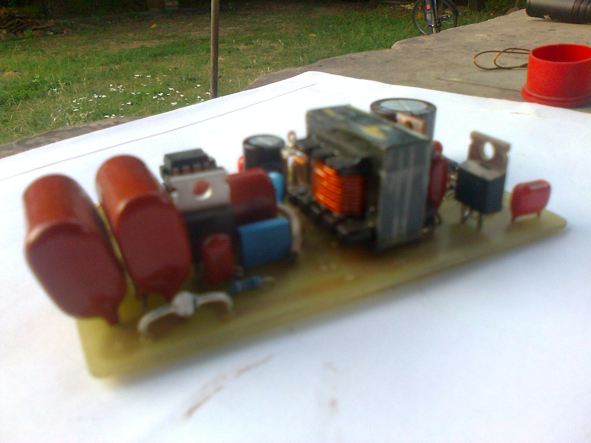
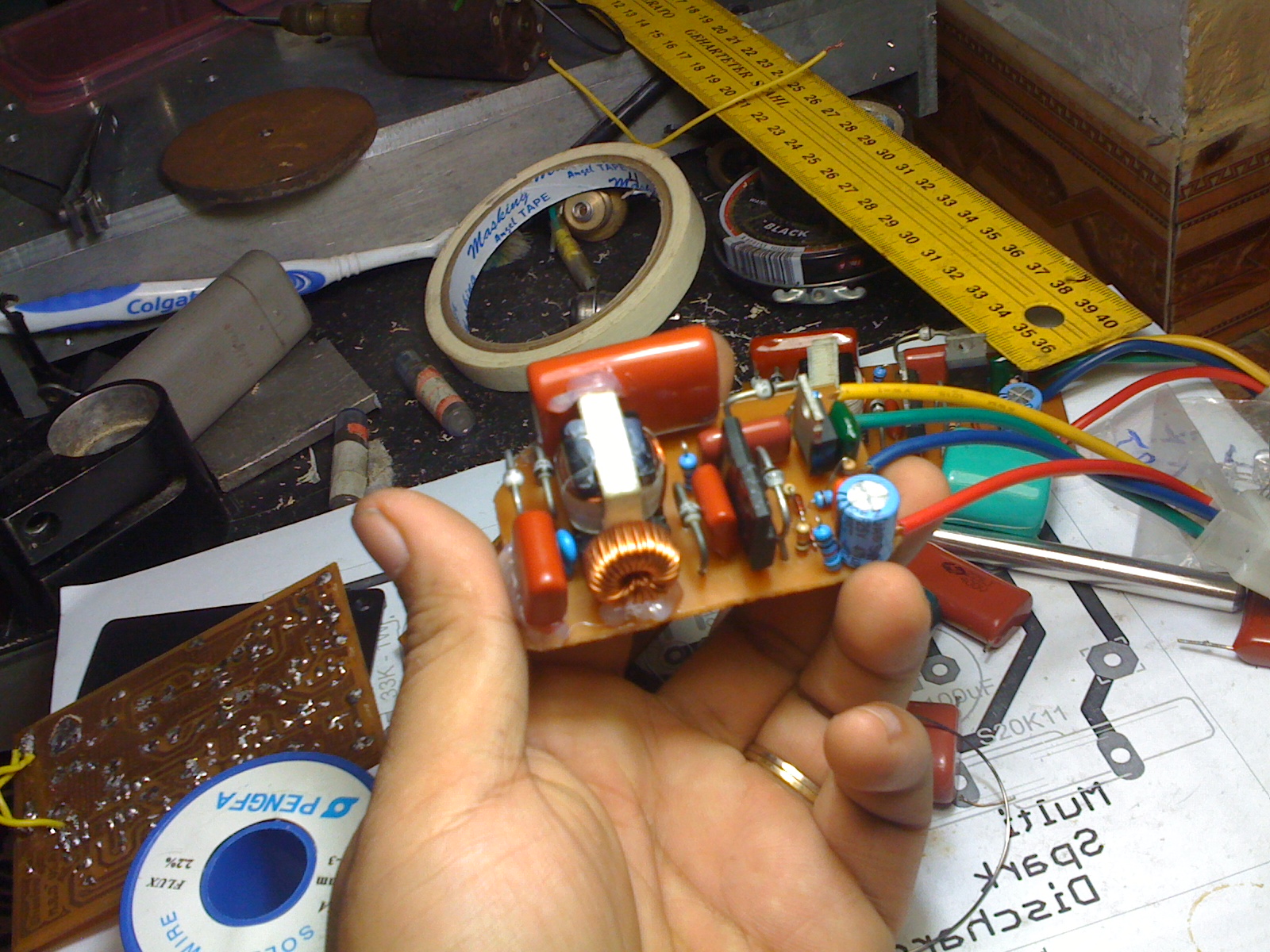
i built this , 220uH L coil ,C is 104 400V,mosfet IRLI540 , 4.7v zener ( tried 6v8 zener) with the same result , Transformer using ferit powder core EI22 ( core area 0.6x0.6 = 0.36cm2 ) primary 17x2 , sec 170 , primary outside sec. . output capacitor is 105 , 630V
its work flawlessly , strong spark , but FET , transformer getting hot when running about 10-15 minutes , i can add heatsink to mosfet , but how about transformer ?
it's get overheat at high rpm(~ 10k rpm) , draw nearly 2A@12V , and resonance frequency drop from 33khz to 24-25khz. tested on test bench and real motocycle ( single cylinder)
i think about limit current to circuit , add some power resistor ?
10-06-2013, 08:46 PM
#1117


Join Date: Sep 2012
Location: Winnipeg, MB, CANADA
Posts: 50
Likes: 0
Received 0 Likes
on
0 Posts
There are 3 things you can do, increase the current capacity (wattage) of the transformer and use a heatsink for the FET, or reduce the input voltage, which will reduce the current and overall power, or limit the current, this will also reduce the overall power. With the 4.7 zeners you could go down to say 6 volts. Try it and see what happens.
Ray
Ray
10-07-2013, 07:51 AM
#1118
Senior Member
Join Date: Feb 2010
Location: szarvas, HUNGARY
Posts: 133
Likes: 0
Received 0 Likes
on
0 Posts
i built this , 220uH L coil ,C is 104 400V,mosfet IRLI540 , 4.7v zener ( tried 6v8 zener) with the same result , Transformer using ferit powder core EI22 ( core area 0.6x0.6 = 0.36cm2 ) primary 17x2 , sec 170 , primary outside sec. . output capacitor is 105 , 630V
its work flawlessly , strong spark , but FET , transformer getting hot when running about 10-15 minutes , i can add heatsink to mosfet , but how about transformer ?
it's get overheat at high rpm(~ 10k rpm) , draw nearly 2A@12V , and resonance frequency drop from 33khz to 24-25khz. tested on test bench and real motocycle ( single cylinder)
i think about limit current to circuit , add some power resistor ?
its work flawlessly , strong spark , but FET , transformer getting hot when running about 10-15 minutes , i can add heatsink to mosfet , but how about transformer ?
it's get overheat at high rpm(~ 10k rpm) , draw nearly 2A@12V , and resonance frequency drop from 33khz to 24-25khz. tested on test bench and real motocycle ( single cylinder)
i think about limit current to circuit , add some power resistor ?
I ask you:
Secondary coil: the bottom?
Primary Coil: top?
https://docs.google.com/file/d/0BxQH...it?usp=sharing
Air gap? (0,1-0,2 mm)
Experiments demonstrate correct 1:10 ratio. Power 12-14V, Secondary voltage~120-140Vx1,41 x2=338--395V)
Use of primary 2x20 winding, secondary 200 winding .
To reduce the ferrite core saturation.
I am using EI28: 2x11 primary winding thread.
Secondary winding 110-120.
No hot components.
Small ferrite cores = low performance.
What kind of performance do you prefer?
Last edited by nyemi; 10-07-2013 at 08:06 AM.
10-07-2013, 05:35 PM
#1119
Junior Member
Join Date: Aug 2013
Posts: 5
Likes: 0
Received 0 Likes
on
0 Posts
Hi Shamino
I ask you:
Secondary coil: the bottom?
Primary Coil: top?
https://docs.google.com/file/d/0BxQH...it?usp=sharing
Air gap? (0,1-0,2 mm)
Experiments demonstrate correct 1:10 ratio. Power 12-14V, Secondary voltage~120-140Vx1,41 x2=338--395V)
Use of primary 2x20 winding, secondary 200 winding .
To reduce the ferrite core saturation.
I am using EI28: 2x11 primary winding thread.
Secondary winding 110-120.
No hot components.
Small ferrite cores = low performance.
What kind of performance do you prefer?
EI22 is rating at 10W , EI28 rating at 20W
wound secondary coil first , primary on top , primary is 2x17 , sec is 170 , input is 12v , output is 338V , and there is no space on transformer to add more winding , i think i must change my transformer to bigger core.EE25 (15W) or EI28(20W)
// i tried to stay with EI22 because it small enought to make it compact design
to NAV-AIDS : tried with 5v ( using PC PSU ) output voltage ~ 150V , it's a huge drop in output when load increase.
another question : how to calculate inductance of primary winding ? in zvs theory , the resonance frequency is determine by L(primary winding) and C ( resonance capacitor) ?
10-07-2013, 08:00 PM
#1120
Senior Member
Join Date: Feb 2010
Location: szarvas, HUNGARY
Posts: 133
Likes: 0
Received 0 Likes
on
0 Posts
Hi Shamino
There are two ideas that may resolve the problem.

Read the scr's soul.
http://www.nxp.com/documents/applica...te/APPCHP6.pdf
Factory cdi ignition core size.
It's not small.


There are two ideas that may resolve the problem.
Read the scr's soul.
http://www.nxp.com/documents/applica...te/APPCHP6.pdf
Factory cdi ignition core size.
It's not small.
Last edited by nyemi; 10-08-2013 at 08:00 PM.
10-08-2013, 07:37 AM
#1121
Join Date: Sep 2012
Location: Winnipeg, MB, CANADA
Posts: 50
Likes: 0
Received 0 Likes
on
0 Posts
Shamino, the point is that the more power you output the more heat that needs to be dissipated. Power and heat is based on the energy stored and released plus the number of cycles (frequency or rpm), the higher the frequency the more heat is generated. You either live with the power level you have or reduce it by whatever means you have like, resistance, impedance, or voltage..etc. MSD ignitions can draw up to 14 amps or more at high rpm and yes they get hot.
Calculate for the primary only.

or use the website calculator: http://www.1728.org/resfreq.htm
Ray
Calculate for the primary only.
or use the website calculator: http://www.1728.org/resfreq.htm
Ray
10-09-2013, 06:31 PM
#1122
Junior Member
Join Date: Aug 2013
Posts: 5
Likes: 0
Received 0 Likes
on
0 Posts
Hi Shamino
There are two ideas that may resolve the problem.
Read the scr's soul.
http://www.nxp.com/documents/applica...te/APPCHP6.pdf
Factory cdi ignition core size.
It's not small.
There are two ideas that may resolve the problem.
Read the scr's soul.
http://www.nxp.com/documents/applica...te/APPCHP6.pdf
Factory cdi ignition core size.
It's not small.
the first block limit the charging voltage to 133 + 150 V to protect ignition coil or limit power consumption ?
the second block turn off ( self commutation) the main SCR before capacitor discharge completely ?
my circuit use pickup pulse from flywheel directly without PIC microcontroller , so i must add second block to turn off main SCR sooner to save some power ?
i will try both solution , add some component and use bigger transfomer Core.
// my current pcb is 42mm x 66mm , it's fit in plastic box i have , the bigger box is 65mm x 90mm so if i add some component or bigger core , i must use bigger box . that's the problem ^^
 02-08-2014, 02:16 PM
#1123
Junior Member
Join Date: Aug 2010
Location: Szeged, HUNGARY
Posts: 11
Likes: 0
Received 0 Likes
on
0 Posts
Hi Guys,
please feel free to try out my timer board. It is based on pic 16f628a at 16Mhz. UI is written in Java. Android app is in progress
if you have any questions please ask it here or by email.
http://csa-electronic.wix.com/index
CheeseE
please feel free to try out my timer board. It is based on pic 16f628a at 16Mhz. UI is written in Java. Android app is in progress
if you have any questions please ask it here or by email.
http://csa-electronic.wix.com/index
CheeseE
07-05-2014, 04:20 PM
#1124
Junior Member
Join Date: Jul 2014
Posts: 1
Likes: 0
Received 0 Likes
on
0 Posts
I have been doing my "homework" on a Homemade CDI for my Homelite 26cc conversion. I have read the threads, here, and chased the subject all over the internet. So, I am not putting off my responsibility to do the research, when I ask for your help.
I would greatly appreciate a simple listing, with links, of Homemade RC CDI's that are complete, working properly, and have the PCB layout, or schematic, parts manifest and programming freely available. I appreciate your help, as I am greatly confused. This might well be placed under a separate thread, with a title noting the summation and comparing the pros/cons of the various units.
Thank you so much for your help and valuable time and effort to reply. My electronics skills are limited and I am having a tough time sorting this out.
Edit: Part of the answer is here. See post #1 and #4.
http://www.rcgroups.com/forums/showthread.php?t=1781959
Last edited by t1d; 07-05-2014 at 08:23 PM.
