


Electronic solutions to modifying glow engines of all sizes to gasoline
 04-22-2025 | 01:01 PM
#2526

Has anyone tried a peristaltic pump? It should work as pump for fuel pressure but it may be able to be used to replace the solenoid if you used a controller similar to the one for the solenoid. Has anyone measured the flow rate the solenoid puts out at different throttle settings? If you knew the flow rates then finding an alternative to the solenoid may be easier because you could set the controller to mimic the flow rates of the solenoid. It may help in finding base settings for something like a peristaltic pump. I know all of you have spent a ton of time working on your present solution so looking for alternatives may not interest you. All of the work you have done is inspiring and I like looking at different ways of doing things. Thanks
 04-22-2025 | 02:03 PM
#2527
Hi everyone!
I did some new conversion during the winter.
First I replaced on my old trainer with the 40FP converted engine, by an OS max-h 40 (with bearing and ring) and clearly like Bert said this engine architecture is most adapt to conversion than bushed engine with ABC piston.
This engine run smoother, and it's really more regular.
Now I'm on a ASP 91FS conversion. It's my first 4 stroke engine, and for now engine run good at wot, but dead at mid range.
I must do more curve adjustment to find the right mixture ratio.
One question for this engine, how do you set the LS screw on the barrel? Completely open? Completely closed? Like OEM setting?

Thanks!
I did some new conversion during the winter.
First I replaced on my old trainer with the 40FP converted engine, by an OS max-h 40 (with bearing and ring) and clearly like Bert said this engine architecture is most adapt to conversion than bushed engine with ABC piston.
This engine run smoother, and it's really more regular.
Now I'm on a ASP 91FS conversion. It's my first 4 stroke engine, and for now engine run good at wot, but dead at mid range.
I must do more curve adjustment to find the right mixture ratio.
One question for this engine, how do you set the LS screw on the barrel? Completely open? Completely closed? Like OEM setting?
Thanks!
04-23-2025 | 12:52 AM
#2528
Wow! Great explanations to my questions. Unfortunately I have some more. Does the solenoid�s action work like a valve? Meaning since it works only on and off to get less fuel you probably increase the on and off pulses. Would a valve that you could control also work? Has anyone looked for a small variable controllable valve? My other question is have you tried using rpm as the way to set the solenoid? If the solenoid reacts to air pressure and temperature then it should be able to react to rpm. You can get rpm from the ignition system and then program in a preferred idle rpm and many other points along the curve and would the solenoid be able to hold the rpm close to what the program called for? Sort of like a gyro holding the plane in the same altitude. The solenoid could hold the engine in the proper rpm setting as long as the throttle wasn�t changed. Thanks again for all the information. Your explanations are easy to understand.
The solenoid does not do that. If it is controlled to 50% duty cycle, it will ALWAYS be 50%, regardless of whatever immediately prior different command was given.
The other very beneficial property is in that a controlled valve gives a laminar flow, an oscillating valve gives a non-laminar flow. YOu can see this in the video, when the solenoid is at 100% dutycycle (stops rattling), the outflow immediately changes to a smooth flow, but during the controlled phase, outflow is non-laminar.�n the case of engines and carburettors, this GREATLY enhances fuel atomisation, leading to significantly leaner mixtures and a much cleaner burn.
As for including RPM in the valve control: Nope... The system still is by and large just an orifice passing fuel based on pressure differences, and the deeper carb vacuum and higher muffler pressure are the correcting factors here. The engine will find a stable operating point, the trick is to find the suitable dutycycle for each throttle position, for the engine to stabilize in an optimal operating point.
Has anyone tried a peristaltic pump? It should work as pump for fuel pressure but it may be able to be used to replace the solenoid if you used a controller similar to the one for the solenoid. Has anyone measured the flow rate the solenoid puts out at different throttle settings? If you knew the flow rates then finding an alternative to the solenoid may be easier because you could set the controller to mimic the flow rates of the solenoid. It may help in finding base settings for something like a peristaltic pump. I know all of you have spent a ton of time working on your present solution so looking for alternatives may not interest you. All of the work you have done is inspiring and I like looking at different ways of doing things. Thanks
04-23-2025 | 01:03 AM
#2529
Hi everyone!
I did some new conversion during the winter.
First I replaced on my old trainer with the 40FP converted engine, by an OS max-h 40 (with bearing and ring) and clearly like Bert said this engine architecture is most adapt to conversion than bushed engine with ABC piston.
This engine run smoother, and it's really more regular.
Now I'm on a ASP 91FS conversion. It's my first 4 stroke engine, and for now engine run good at wot, but dead at mid range.
I must do more curve adjustment to find the right mixture ratio.
One question for this engine, how do you set the LS screw on the barrel? Completely open? Completely closed? Like OEM setting?
Thanks!
Now you need to connect the solenoid driver, and set your fuel curve. Topside should be no real issue. If idle results in very low curve values, close the LS needle a little bit, this forces you to raise the curve at the low RPM end a bit.
Ideally, you should set the LS needle such, that idle occurs with a curve value (-100 to +100) of about -50. This will provide sufficient resolution.
Thye problem with really low values like -90 for example, is that if your TX has a resolution (step size) of "1", that represents only 0,5% of TOTAL range.
But if your set value is -90, then a change to -89 or -91is a step of 10% in fuel the engine gets extra or less. Those steps are way too coarse.
Closing the LS needle, pushing the value of the curve up to say, -50, then a change of +/- 1 point, is only a change in fuel of 2%, which is more acceptable.
This is a matter of testing and experimenting. Once you have done a few different engines, you will get a feel for how to set up the curve, and which strategy yields better or less desirable results.
There is no real fixed receipe, just "general guidelines".
Last edited by 1967brutus; 04-23-2025 at 01:05 AM.
04-23-2025 | 09:48 AM
#2532
 04-24-2025 | 06:55 AM
#2533
Checking my JR TX, it is limited to 5 point curves. Lonnie suggested that would work.
My personal position however is that conversions are working for me without remote metering and that likely because of not being too fussy about midrange.
Currently the following spark ignition and gas conversions are flight ready on fleet planes.
My personal position however is that conversions are working for me without remote metering and that likely because of not being too fussy about midrange.
Currently the following spark ignition and gas conversions are flight ready on fleet planes.
- Saito 182 T
- Saito 180
- Saito 125a
- Saito 100
- Saito 90TS
- Saito .65
- Saito .30 (two)
- OS .52 Surpass (converted and tested to install in a 48" that is near build completion)
05-05-2025 | 08:36 PM
#2539
Oh? That's weird?
The .50 class fourstrokes are among my favourite engines for conversion. I consider them ideal, and I have four of them currently running, and 2 more on the shelf (all of them ASP by the way, but I see no reason why OS would not convert just as well).
What were your issues? My guess would be that heat insulation (decoupling) of the carb was insufficient, as that is the only reason I can think of.
05-06-2025 | 04:49 AM
#2540
My Feedback: (1)
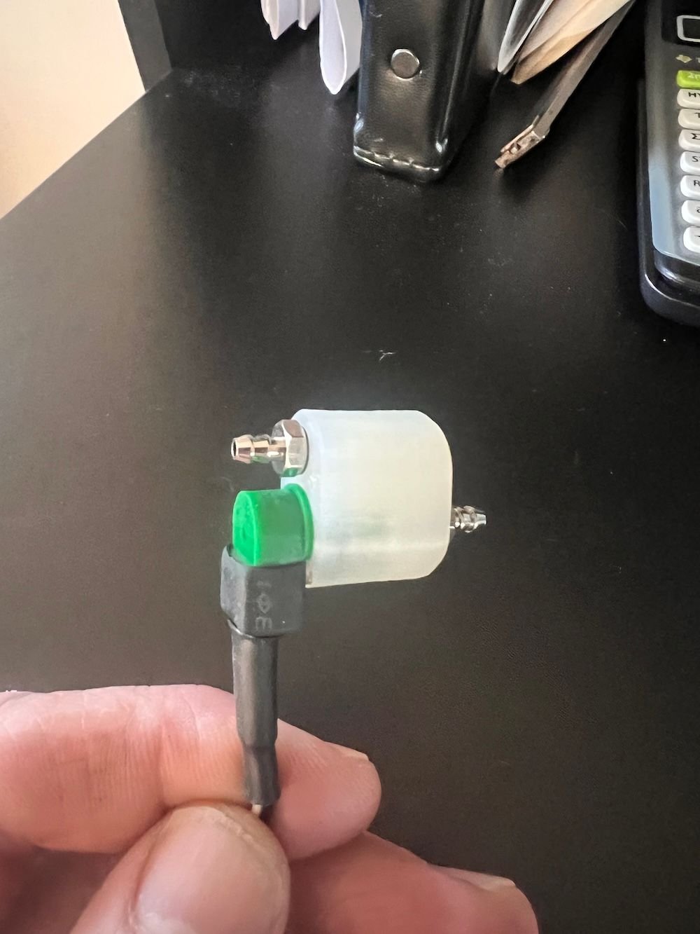
SO.... This little project took a lot more fiddling than one would think but I have finally succeeded at 3D printing a Solenoid housing. Made in Nylon (PA) for fuel resistance the Print parameters needed much tweaking to get a liquid tight seal and tolerances for the housing bore - But its now repeatable on higher end printers I would think.
This is just an offshoot of a bigger trial to print an "all in one" pulse pump and fuel control "block" - getting close on that one too but fighting getting the unit to seal up tight. Have a working unit but its still a little leaky...

This is just an offshoot of a bigger trial to print an "all in one" pulse pump and fuel control "block" - getting close on that one too but fighting getting the unit to seal up tight. Have a working unit but its still a little leaky...
05-06-2025 | 04:55 AM
#2541
A little hard to put words to. Perhaps the best is that it was tempermental. You could be correct that heat was getting to the carb as it would suddenly die when otherwise running full power with a correct mixture. A mica mounting gasket on the carb base might have been prudent.
Full power would fluxuate by 500 rpms. It also took a full 2 sec servo slow down to avoid spool up stumble. I've never needed more than .7 with Saito conversions. When spooling up, it would reach a full power plateau of 7500 rpms on an APC 12x6 and then after perhaps 4-5 seconds then creep up to 8000 and then migrate between.
On nitro it goes to 9500 and is rock steady.
Honestly, I didn't do it full effort because of it size... concerned it didn't have the power needed when running gas. On gas it is a full 1500 - 2000 rpm below nitro. And the designated plane probably needed a .65 conversion but the .52 is what was available.
I hate to regress back to the days of stuck valves and messy clean up and should it have excess power than needed for the plane... I might revisit running it on gas. The plane is a 48" RCM Basic Pipe that calls for a .40 2 stroke.
05-06-2025 | 12:39 PM
#2542
SO.... This little project took a lot more fiddling than one would think but I have finally succeeded at 3D printing a Solenoid housing. Made in Nylon (PA) for fuel resistance the Print parameters needed much tweaking to get a liquid tight seal and tolerances for the housing bore - But its now repeatable on higher end printers I would think.
This is just an offshoot of a bigger trial to print an "all in one" pulse pump and fuel control "block" - getting close on that one too but fighting getting the unit to seal up tight. Have a working unit but its still a little leaky...
This is just an offshoot of a bigger trial to print an "all in one" pulse pump and fuel control "block" - getting close on that one too but fighting getting the unit to seal up tight. Have a working unit but its still a little leaky...
05-06-2025 | 01:07 PM
#2543
A little hard to put words to. Perhaps the best is that it was tempermental. You could be correct that heat was getting to the carb as it would suddenly die when otherwise running full power with a correct mixture. A mica mounting gasket on the carb base might have been prudent.
Full power would fluxuate by 500 rpms. It also took a full 2 sec servo slow down to avoid spool up stumble. I've never needed more than .7 with Saito conversions. When spooling up, it would reach a full power plateau of 7500 rpms on an APC 12x6 and then after perhaps 4-5 seconds then creep up to 8000 and then migrate between.
On nitro it goes to 9500 and is rock steady.
Honestly, I didn't do it full effort because of it size... concerned it didn't have the power needed when running gas. On gas it is a full 1500 - 2000 rpm below nitro. And the designated plane probably needed a .65 conversion but the .52 is what was available.
I hate to regress back to the days of stuck valves and messy clean up and should it have excess power than needed for the plane... I might revisit running it on gas. The plane is a 48" RCM Basic Pipe that calls for a .40 2 stroke.
Full power would fluxuate by 500 rpms. It also took a full 2 sec servo slow down to avoid spool up stumble. I've never needed more than .7 with Saito conversions. When spooling up, it would reach a full power plateau of 7500 rpms on an APC 12x6 and then after perhaps 4-5 seconds then creep up to 8000 and then migrate between.
On nitro it goes to 9500 and is rock steady.
Honestly, I didn't do it full effort because of it size... concerned it didn't have the power needed when running gas. On gas it is a full 1500 - 2000 rpm below nitro. And the designated plane probably needed a .65 conversion but the .52 is what was available.
I hate to regress back to the days of stuck valves and messy clean up and should it have excess power than needed for the plane... I might revisit running it on gas. The plane is a 48" RCM Basic Pipe that calls for a .40 2 stroke.
I use very simple plain unpainted plywood of approx 2 mm (0,08") thickness. Is easy to make, and the oldest is still holding out excellent after 8 or 9 years.
05-06-2025 | 01:08 PM
#2544
SO.... This little project took a lot more fiddling than one would think but I have finally succeeded at 3D printing a Solenoid housing. Made in Nylon (PA) for fuel resistance the Print parameters needed much tweaking to get a liquid tight seal and tolerances for the housing bore - But its now repeatable on higher end printers I would think.
This is just an offshoot of a bigger trial to print an "all in one" pulse pump and fuel control "block" - getting close on that one too but fighting getting the unit to seal up tight. Have a working unit but its still a little leaky...
This is just an offshoot of a bigger trial to print an "all in one" pulse pump and fuel control "block" - getting close on that one too but fighting getting the unit to seal up tight. Have a working unit but its still a little leaky...
05-06-2025 | 07:28 PM
#2545
My Feedback: (1)
Its one of those "unintended" designs Bert.. I like it too as it's very compact and inline. I wasn't intentionally going for this but I have found if I print with the "openings" at both ends its easier to get a tight seal than if the openings are on the sides and break the continuous outer loops. The ability to do blind internal holes is neat..

05-14-2025 | 05:33 AM
#2547

what does it take to print in nylon? could i do it on my ender3? what printing parameters did you use? this is dangerously close (with a few modifications) to a module with all th electronics and whatforth in a single package.
Its one of those "unintended" designs Bert.. I like it too as it's very compact and inline. I wasn't intentionally going for this but I have found if I print with the "openings" at both ends its easier to get a tight seal than if the openings are on the sides and break the continuous outer loops. The ability to do blind internal holes is neat..
05-14-2025 | 10:27 PM
#2548
My Feedback: (1)
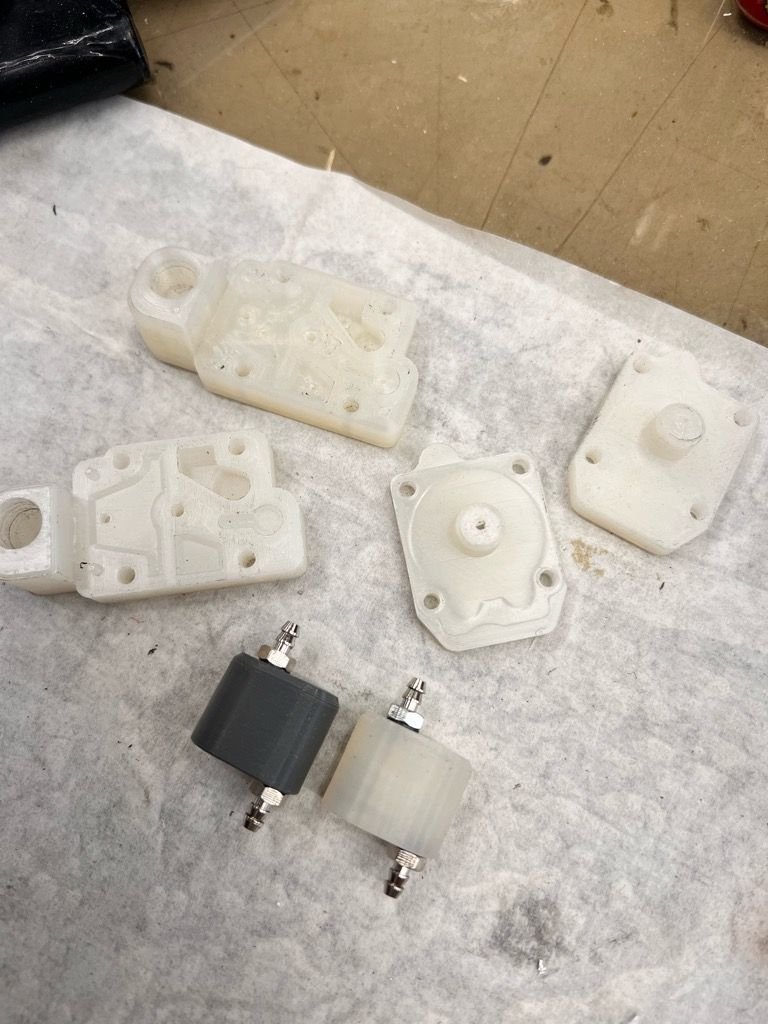
I have found there are many versions nylon(PA) and some are very tricky... the best bet is to try Overture Easy Nylon which is a low temp version that seems to be giving the best results for me. Many test pieces were made to get the "fill" right to make a leak proof part but now it seem to be repeatable. Also the dimensions of the bore have to be tweaked to end up with a precise fit. I have a trick i'm working on to make this easier and is used with a "post print" annealing process but will share that latter when its all sorted out.
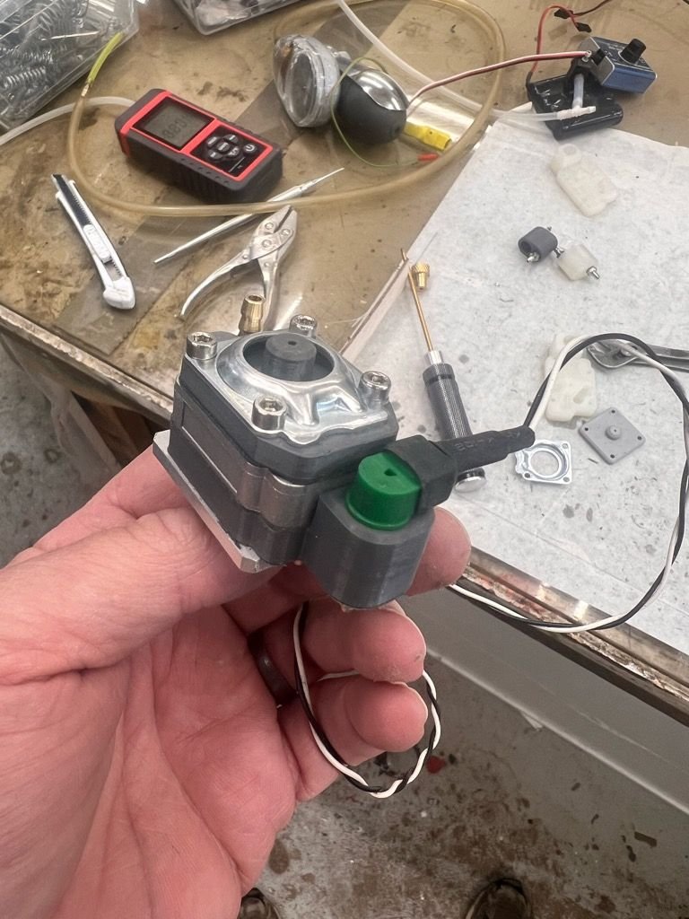
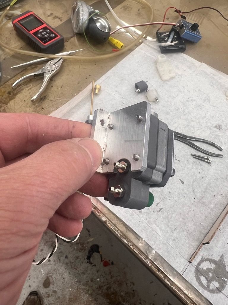
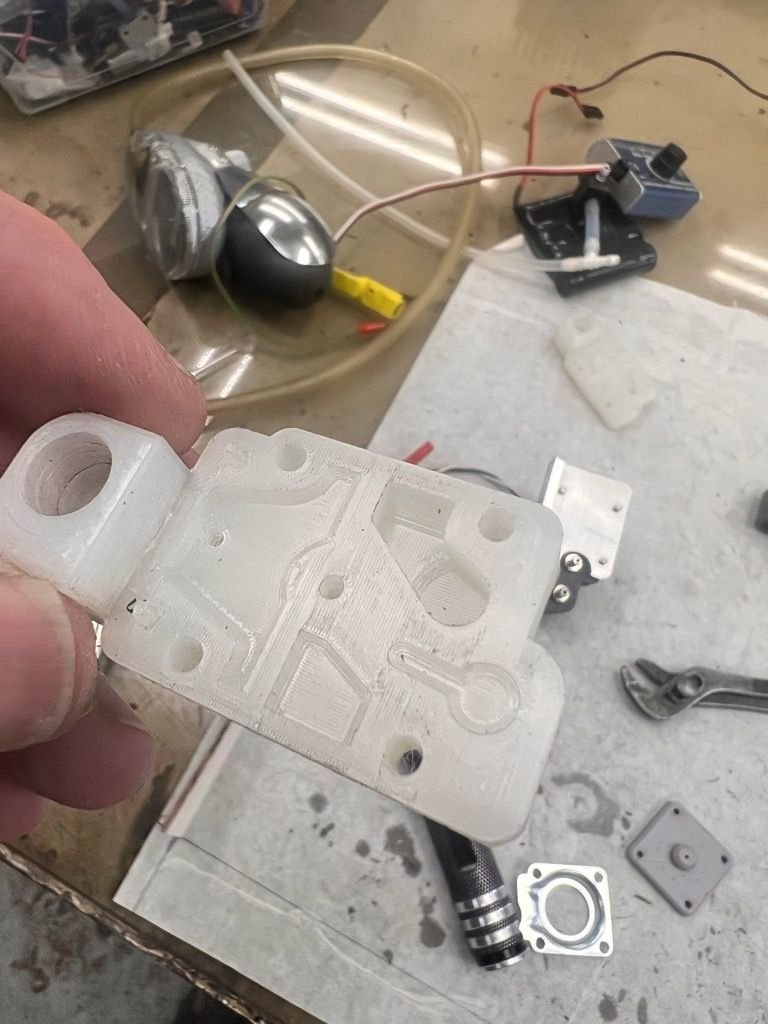
As a single package unit here is my effort so far - have a leak proof workable copy now and am working on printing the last piece which is still a takeoff of the $18 Amazon carb. This is an all in one Pump/regulator/ controller. Some of my test pieces also shown..
I would think your ender is capable of this type of printing with patients and some testing. Nylon is a great filament for RC stuff if you can sort it out.

 05-15-2025 | 10:46 AM
#2549
I sincerely do not know if an "all in one" setup is that desirable.
I can see the appeal, but personally, I really do not want to give up on the freedom to place the temp/press sensor to a place of my liking.
I can see the appeal, but personally, I really do not want to give up on the freedom to place the temp/press sensor to a place of my liking.
05-18-2025 | 09:39 AM
#2550
Isn't the engine compartment the best place to mount it? Seems like it would be, especially with cowled engines.

