


Electronic solutions to modifying glow engines of all sizes to gasoline
 09-16-2025 | 08:07 AM
#2701
In vehicles, ti is a bit slower (typically less than 0,5 Hz) and more "feelable" than audible or visible on the gauges. You don't really see RPM or speed oscillate, you don't really hear it, but you feel a distinct light "tugging" on the seat of the pants so to say.
Over here in Europe it is a very common thing with ethanolated gasoline in carburated cars and bikes... There are certain fuel additives that cure the issue up to 10% of ethanol, but rejetting the carb will also cure it.
 09-16-2025 | 09:41 AM
#2702
In OpenTX unless I'm missing something, you only have the ability to change the curve value by integers, so 5 percent is 5 percent.. Thankfully the range is -100 to +100. I suppose the multiply function could be used in the fashion you mentioned, never had case to use the multiply function so I don't know how it works.
I have my temperature alarm set at 300F, in 5 years I got one alarm, this was while performing a Chandelle during a scale contest where the ambient temp was 95F. I normally don't fly when it is that hot, but in my mind adding a little fuel to hot engine can't hurt.
I have my temperature alarm set at 300F, in 5 years I got one alarm, this was while performing a Chandelle during a scale contest where the ambient temp was 95F. I normally don't fly when it is that hot, but in my mind adding a little fuel to hot engine can't hurt.
If I remember correctly, that programming worked by means of running the fuel channel with its associated curve through an extra imput and having the measured value (or the knob/slider position) influence the "weight" function of that imput. but it is a bit hazy right now (long time ago, and this weekend I had a mishap that forced me to take quite a bit of morphine so my brain is not too bright today and probably for one or two days coming).
Last edited by 1967brutus; 09-16-2025 at 10:49 AM.
 Working on that... Thanks. Been through sheer hell for a few days.
09-18-2025 | 06:06 AM
Working on that... Thanks. Been through sheer hell for a few days.
09-18-2025 | 06:06 AM
#2705

dear all,
after reading the whole thread here, I am sure this is the way to go for running my older .61 four stroke on gasoline, but unfortunately I am still a little bit lost...
I am familiar with some basic arduino programming, and also keen on 3D printing.
I saw pictures of some machined bodies for the solenoid as well as a completely 3D printed version. Could anyone post a link or share these files please for the "latest" version?
Sorry for this kind of questions, but I could not manage to find, yet.
Thank you very much.
best regards.
09-18-2025 | 11:30 PM
#2706
The print files are basically "continuous development", the metal bodies, there is only one version.
There is a drawing somewhere of the metal body, most likely place to find it is Dave's Github.
Normally I supply those, but stock has been depleted and I have to still order a new batch.
I believe you should ask Chris (Cat1) for the latest printfiles.
There is a drawing somewhere of the metal body, most likely place to find it is Dave's Github.
Normally I supply those, but stock has been depleted and I have to still order a new batch.
I believe you should ask Chris (Cat1) for the latest printfiles.
The following users liked this post:
bauso (09-18-2025)
10-05-2025 | 09:41 AM
#2707
My Feedback: (1)
dear all,
after reading the whole thread here, I am sure this is the way to go for running my older .61 four stroke on gasoline, but unfortunately I am still a little bit lost...
I am familiar with some basic arduino programming, and also keen on 3D printing.
I saw pictures of some machined bodies for the solenoid as well as a completely 3D printed version. Could anyone post a link or share these files please for the "latest" version?
Sorry for this kind of questions, but I could not manage to find, yet.
Thank you very much.
best regards.
after reading the whole thread here, I am sure this is the way to go for running my older .61 four stroke on gasoline, but unfortunately I am still a little bit lost...
I am familiar with some basic arduino programming, and also keen on 3D printing.
I saw pictures of some machined bodies for the solenoid as well as a completely 3D printed version. Could anyone post a link or share these files please for the "latest" version?
Sorry for this kind of questions, but I could not manage to find, yet.
Thank you very much.
best regards.
I have spent much time trying to get a repeatable and reliable 3D printed solenoid housing and its very difficult to make a reliable seal and get the tolerances needed for the "bore" to be reliable... My best luck has been with nylon (both regular and glass filled) but then it requires a post print "heat treatment" using a precise steel "bore mold" to get a precise fit.
I can share a file to print if you would like to try. I have reverted to machining my housings out of delrin (acetal) on my small CNC mill - I can get much more repeatable results this way.
Send me a PM with your email if you would like to try the file..
12-05-2025 | 02:44 PM
#2708
Work is slowing on my 30% Piper Cherokee built so today decided to look at mounting the Zama carb on the Roto 85 FS. This engine was purchased around late 2018. During the built the carburetor flange was broken on the intake manifold. Little info was available at that time and I purchased the engine from an importer on Ebay. Made up a piece of aluminum that is screwed and glued on with JB weld. The repair worked well over the 5 year period that I flew the plane. The second engine I purchased a few years ago has a much more robust intake manifold.
The hole in the intake is 1/2" in diameter, the original Walbro WT962 has a 14mm bore, and the new Zama needs a 20 MM bore to accommodate the black plastic piece. The plastic piece sticks out about 1/2" from the flange on the carb, see second photo. I plan the make a isolator plate out of 3/8" G10. The plastic piece is there for the idle circuit.
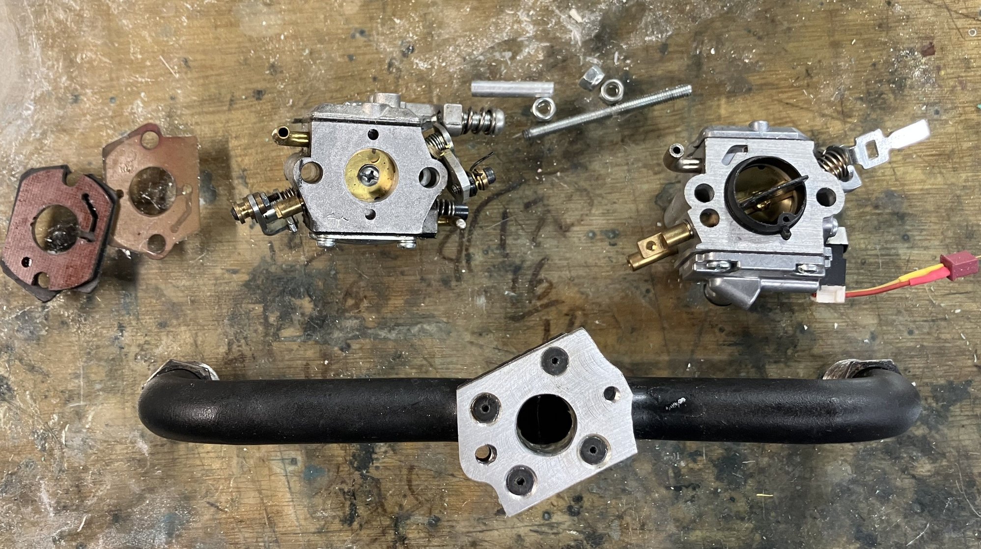

The hole in the intake is 1/2" in diameter, the original Walbro WT962 has a 14mm bore, and the new Zama needs a 20 MM bore to accommodate the black plastic piece. The plastic piece sticks out about 1/2" from the flange on the carb, see second photo. I plan the make a isolator plate out of 3/8" G10. The plastic piece is there for the idle circuit.
Last edited by Tony Hallo; 12-06-2025 at 03:35 AM.
 12-24-2025 | 10:52 AM
#2710
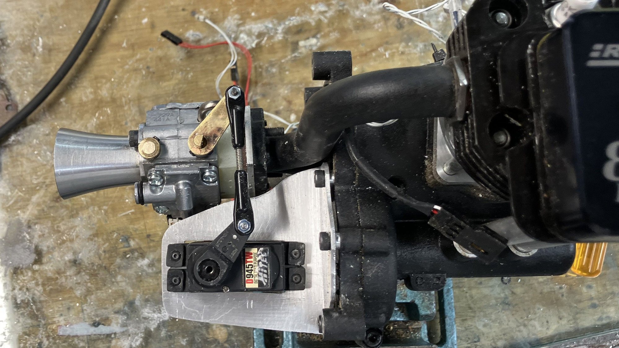
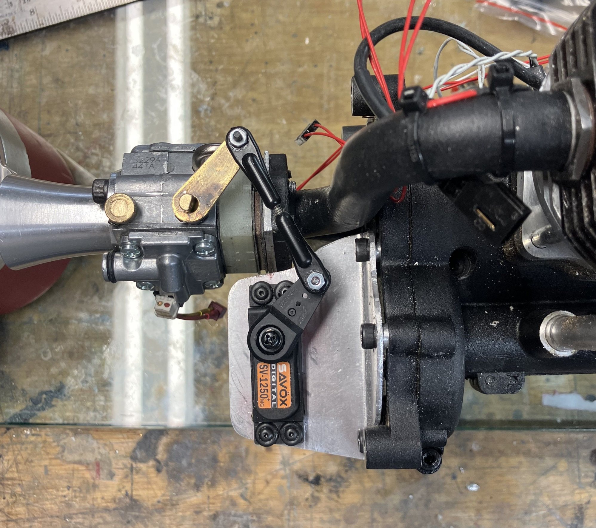
I set out to find a servo that has a high operating temperature, all seem to be in the 50 to 60 C range. The search came up empty. Both the GP178 EFI and Roto 125FS use a Savox brand servo so that is what I ended up using although the specs are on the low side at 50C. Using the same SV1250MG that is used on the GP178 EFI engine. Rated at 111 in-oz of torque, the servo wasn't happy at high throttle setting as the spring is rather stiff on ZAMA carb, so the spring was unhooked. The engine is ready for tuning.
01-01-2026 | 07:37 AM
#2711
About ready to tune the engine, waiting for a warm spell, less than 20F now.
The throttle servo is set for a 1 to 1 movement, so that 1 degree on the serov moves the throttle plate 1 degree. The throttle channel is controlled via exponential curve, the solenoid channel is controlled by a curve used by Jim Thompson. The S1 slider is set to add or subtract 15% from the solenoid curve for tuning. The engine is equipped with RPM and cylinder temperature indication. Pressing switch SI will play the current output value of the throttle stick and the solenoid channel. Each click on the throttle stick is approximately a 10% move from -100% to +100%, thinking i will tune at each click, then plot the data and fit it to whatever point curve makes sense in OpenTx.
Am I missing anything?
01-07-2026 | 02:16 PM
#2712
Because at full throttle (high end of the curve, where the values are high as well) 10 or 15% more or less fuel isn't that bad, it's a fairly decent range of adjustment.
But at lower throttle settings, where the curve is low, 15% more or less WILL kill your engine. Probably 5% allready will.
What you need to do, is set up the programming such, that the curve is fed to an unused channel (say, channel 17 or higher, one you do not have a servo connection for) and then set up S1 such that it affects the "weight" of that channel. Then link the output of that channel 17 back to the channel you hook up the solenoid to.
That way, adding 1% of fuel by means of the slider, will be 1% of the actual curve value that you are running at at that time.
Set S1 in neutral and set up a running curve on the ground. Go fly, and whenever you detect a spot on the throttle range where the engine is not running to your liking, you can carefully tune, for no other purpose than to determine whether that rough spot is lean or rich, return the slider to neutral (these sliders should have a tactile neutral position), land, and adjust the curve accordingly.
Be very careful when doing this, because airborne, "running optimal" and "flame out" are VERY close to each other, there is not much of a lean range between those two points, and at times, rich and lean are hard to distinguish by exhaust note alone. Therefore, when adjusting, ALWAYS first test towards "richer". If running improves, you were apparently in that very narrow lean range, if running deteriorates, you know you were running too rich.
A first adjustment towards lean because you THINK you heard a rich run, in case you misheard, will cause a flameout and a deadstick landing.
01-08-2026 | 03:29 AM
#2713
Had a little extra time yesterday and decided to start the engine. Solenoid off , ignition on, choke off, after a dozen or so flips the engine started and ran. Shut it off and turned the solenoid on. Had the throttle trim set to the max. Started again and attempted to reduce the idle speed after a short warm up, was running at 3400 rpm, with the trim was able to reduce the engine speed to 3000 rpm. While at 3000 rpm turned the slider to full positive position and slowed the engine and turned to the negative side and was able to kill the engine. I did not remove the idle stop screw when the carb was installed. Shut the engine off and removed the carb to remove the idle stop screw and reset the throttle travel.
My channel output is -100 to 100, with the slider set to add 15% this gives the ability the change the output by 0.1 %, I feel good with this.is good. I'm only guessing here but I think the carb is not as sensitive because the engine much larger than the conversions done on glow engines.
At any rate I really enjoyed doing the conversion and expanded my knowledge in the Arduino world, thanks to all that the paved the way!
01-10-2026 | 05:59 AM
#2714
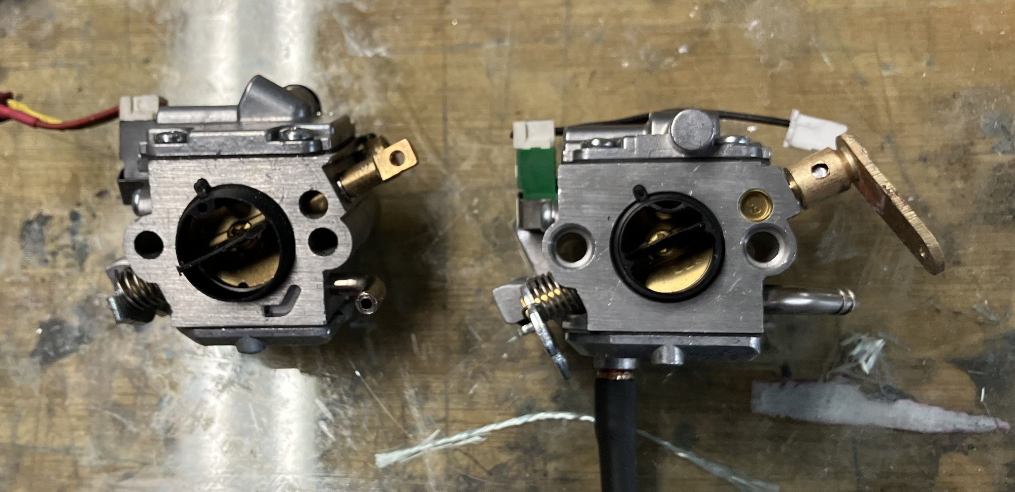
With the carb back on and the throttle servo reset started and ran the engine, lowest possible idle when leaned out was about 1600 rpm, this engine would tick over at just over 1000 rpm with the WT 962 carb installed. When I look at the throttle disc you find the small slot where the idle jet is and there is also a second slot about 160 degrees across, I have not seen this second slot on other carbs.
When I compare the slot in the WT 962 carb it is much smaller than either of the slots on the ZAMA. I would estimate the slot area to be about 6X that of the WT962. I would like to have the idle set before completely the final tuning. Going over the gaskets and heat isolators, might find an air leak.
Here's a
of the engine idling after landing, the speed is 1020 RPM.

When I compare the slot in the WT 962 carb it is much smaller than either of the slots on the ZAMA. I would estimate the slot area to be about 6X that of the WT962. I would like to have the idle set before completely the final tuning. Going over the gaskets and heat isolators, might find an air leak.
Here's a
01-12-2026 | 10:47 AM
#2715
My Feedback: (1)
Hello All,
I hope that you have all arrived in 2026 Healthy and Happy.. Busy holiday season here for me but back to normal now. My retirement seems to be a bit busier than I had anticipated, but I am getting a bit more time in the shop than I have had the past many years.
Thought I would share a little unrelated project as I know some of you will get a kick out of it.. Don't want to plug up this thread so I will just link to my post on our Canadian forum..
https://www.rccanada.ca/rccforum/sho...77#post4135277
best regards..
Chris
Last edited by Cat 1; 01-12-2026 at 11:12 AM.
01-16-2026 | 07:56 AM
#2716
Found another carb for the MS201TC saw that has a smaller bore, it's on the way, may need to make a smaller heat insulator to hold the black plastic piece in place, we shall see. Should be here next week. I believe the existing carb is for a 55cc saw, the MS 201 TC is 35cc.
 01-24-2026 | 08:40 AM
#2718
My Feedback: (1)
Hey all..
A little experiment on an alternate method to control mixture. This popped into my head as I woke up one morning and needed to try it. It seems to work and needs some more experimentation. Need to get it on servo control on both throttle and bleed and use curves. It's simple as there is no need for the solenoid or electronics because the valve is straight from a radio channel.
Chris
01-24-2026 | 03:23 PM
#2719
Hey all..
A little experiment on an alternate method to control mixture. This popped into my head as I woke up one morning and needed to try it. It seems to work and needs some more experimentation. Need to get it on servo control on both throttle and bleed and use curves. It's simple as there is no need for the solenoid or electronics because the valve is straight from a radio channel.
https://www.youtube.com/shorts/TODWwPX67Xg
Chris
What I am wondering is how sensitive the secundary air intake (the airbleed) will be to dust collection, and how stable it will be over the range of ambient conditions.
That is no criticism, just genuinely wondering becvause I have never overhtought THIS particular approach of instead of modulating the fuel, modulating the bleed-airflow.
I absolutely like the idea for its simplicity and for its "being understandable".
I doubt however, if a temperature and atmospheric compensation like we had on the solenoid would be easily achievable, because it is harder to quantify things..
01-24-2026 | 04:19 PM
#2720
My Feedback: (1)
Bert,
This just needs some testing. I'm not thinking it will ever be as precise as a solenoid fuel control but I do think the setup and concept might allow for a "simpler" setup for the majority gas conversions. The midrange effect seems predictable and strong - Less so on the top end, and very pronounced down at low throttle settings - but it did react exactly as I had predicted. It might also have an application on the "walbro" carbed gassers, where mid range richness is a common issue.
My plans are to build a more precise valve (still simple) and get it working on a curve from the radio. I have a Magnum 91-4 stoke getting cleaned up as a planned conversion test mule.
01-25-2026 | 02:36 AM
#2721
I've gotta admit, it is a real nice simple solution. It does require somehow a twin needle carb, otherwise you run into issues with RPM control.
Basically, it is the opposite of what I use for my boat engines that run predominantly constant RPM, where I use the smallest availlable single needle carb, but install a calibrated air orifice outside of the air intake to keep the fuel/air ratio constant with varying load. That orifice shifts the point of pressure-drop when the throttle is opened, increasing fuel suction when the throttle is opened.
But that solution is "not-RC-adjustable". That solution works but is very limited in its application, both WRT RPM and power output.
Yours allows full RPM range and power output. I like it!
02-01-2026 | 09:56 AM
#2722
My Feedback: (1)
Hey all�.
got a better test on the stand for the bleed mixture control and things are looking positive. A old magnum 91 was dug out of the engine box and got cleaned and some new bearings and is bone stock except for the ignition and a bleed added to the intake. This one already had a nipple on the intake but it was replaced with a 5mm one which has a 2.5mm bore. The video shows the initial curve which made it work and it�s as expected. The bleed is shut at idle and at top end and mix is by needles there.
I think this might have possibilities as a simple (but maybe a bit less precise) solution to convert glow to gas. More testing planned but it�s up and running faster than most of my conversions.
02-02-2026 | 03:10 AM
#2723
I have to absolutely say, I am pleasantly surprised how well that runs and how happy it accepts throttle...
You definitely have something there, Chris, MOST definitely.
Curious whether and if/how gravity/inertia affects the system (if at all), in other words, whether it is affected by flightconditions, but first impression is pretty much immaculate.
You definitely have something there, Chris, MOST definitely.
Curious whether and if/how gravity/inertia affects the system (if at all), in other words, whether it is affected by flightconditions, but first impression is pretty much immaculate.
02-02-2026 | 05:39 AM
#2724
My Feedback: (1)
Bert,
My very rudimentary test and intuition seemed to hit the sizing for the valve quite close on this first try. The "max opening" is in a good range. I'm assuming as the engine size increases and the intake volume follows an upsize in the valve might be required. My initial test were with a fuel needle valve and that didn't work as it didn't flow enough. The testing showed response when I simply squeezed a larger fuel tube attached to the intake so valve size was determined off that. One thing to mention is this engine would not run mid range without the valve - its just way to rich.
Flight dynamics might have an effect as you noted and that remains to be tested. I am using the muffler pressure/Crap trap as we know that is proven. The Intake "pull" should follow RPM so I'm thinking that might be somewhat self correcting at least in mid range and higher. Next plans are to try this on a "baby" (.40) four stroke and a two stroke to see it its repeatable across different engines. Want to make sure this test on the .91 is not an anomaly.
One thing that impresses me is the throttle response with this setup - No slowing of thottle servo is required. Im assuming the Bleed flow might be "self correcting" as the throttle is opened quickly ( Intake suction drop) and enriches the mixture to get the engine sped up - Like a mock accelerator pump.
02-02-2026 | 10:07 AM
#2725
One thing that impresses me is the throttle response with this setup - No slowing of thottle servo is required. Im assuming the Bleed flow might be "self correcting" as the throttle is opened quickly ( Intake suction drop) and enriches the mixture to get the engine sped up - Like a mock accelerator pump.
Then again, it could also be a lucky strike with differences in the individual runtimes of the servo's.
A nice test would be to use a very fast servo on the air bypass valve, and see if you can affect acceleration behaviour by affecting the runtime of the bypass-valve servo. Not so much "improve" but to determine if there is a relation between the speed of the bypass valve servo and the acceleration behaviour.
Regardless of that, I really am impressed, and looking forward to flighttesting.
Last edited by 1967brutus; 02-02-2026 at 10:11 AM.

