


Electronic solutions to modifying glow engines of all sizes to gasoline
 02-06-2026 | 09:49 PM
#2726

My Feedback: (1)
A bit more testing today. The magnum got a bigger prop and still preformed like an electric motor - this one seems perfect on the stand.
Just to prove out the theory I mounted up an old and tired Saito .40 and in short order had it running fairly well also with very similar needs for auxiliary bleed curve. This one was a little bit tricky with the interaction between the high and low needles but got it relatively running ok relatively quickly.
Just to prove out the theory I mounted up an old and tired Saito .40 and in short order had it running fairly well also with very similar needs for auxiliary bleed curve. This one was a little bit tricky with the interaction between the high and low needles but got it relatively running ok relatively quickly.
 02-09-2026 | 02:22 AM
#2728
Both seem to run impressively well, Chris!
Now I would think, a small 3D-printed valve that mounts directly on the output shaft of a microservo, and it would make a really nice compact and small set-up.
And here I was, thinking that the solenoid principle could not be improved upon, but what you are showing here is pretty competetive, if not downright "challenging the throne"...!
Last edited by 1967brutus; 02-09-2026 at 03:38 AM.
02-09-2026 | 06:27 AM
#2729
My Feedback: (1)
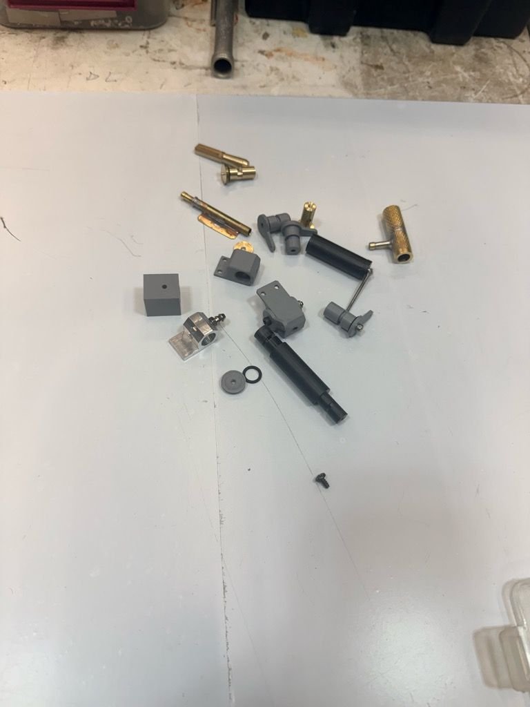
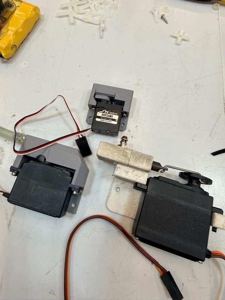
Great minds think alike Bert... Working on a compact and simple design but was struggling a bit. My mind works funny and most "solutions" come to me at night apparently and manifest as soon as I awake. Trying something now that came to me this morning that might be a valid solution. Attached are previous try's that all had promise but were not easy to package. The ability to print this would also be of great benefit for "distribution"
The valve must be somewhat linear and have good repeatability. While at first I thought an airtight seal was necessary, I have found that a small leakage under vacuum is actually beneficial. If sealed very tight, the tube at the takeoff can accumulate some vapour and fuel droplets and choke the engine when coming off idle.
Nowhere near dethroning the solenoid yet as much testing to be done - The Magnum 91 is impressive though as I have never seen such a smooth running and happy engine on a bench - converted or not. Unfortunately I don't have a plane of that size to bolt it in readily. When I finalize a simple valve I will get it in the air on something.
02-09-2026 | 08:13 AM
#2730
My thought actually was a sort of rotary valve that directly bolts on the servo, the valve spindle being in line with the servo output shaft.
3D printing should have no issues with a serrated hole connecting with the serrated outputshaft.No seals needed, just enough clearance for the spindle to move.
Not home right now, but Wednessday evening I'll draw uop a rough sketch.
3D printing should have no issues with a serrated hole connecting with the serrated outputshaft.No seals needed, just enough clearance for the spindle to move.
Not home right now, but Wednessday evening I'll draw uop a rough sketch.
02-09-2026 | 08:28 AM
#2731
My Feedback: (1)
Here is where I am- just as you describe. A small printed rotor against a flat seal plate with a hole. The curve is �area ruled linear� for the hole as it turns through 90 degrees. The plate was going to have a oring for seal and some seat pressure but I think I will try some foam tape as all orings I have are on the stiff side. The seal plate and rotor will be in a printed �box� that attaches to the top of the servo using the original mounts.
02-09-2026 | 11:05 AM
#2732
Something like that, absolutely would work...
My thoughts however were more along the lines of something suitable for a microservo, to keep it as light and compact as possible.
A bit like a plugvalve. Since you can print 3D, square holes (linear area increase) in the plug and body should not be an issue to print, no?
Although I an not sure if linearity really is that important, given the free programmability of the curve.
But what I am thinking is, it might be a bit more "size limited" (a smaller engine requiring a narrower valve passage than a larger engine).
I have to say, I absolutely like this...
02-09-2026 | 01:54 PM
#2733
My Feedback: (1)
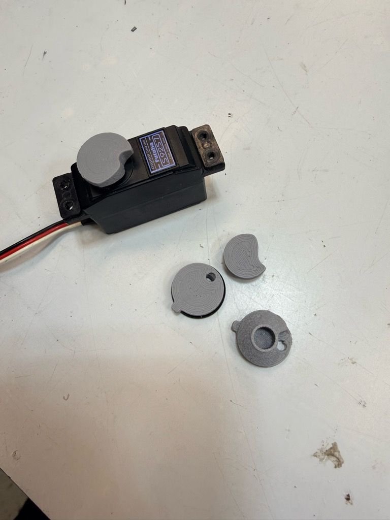
This is a mini servo�only because I don�t have a micro with what I would call good resolution. It�s smaller than the first version.
Send me a drawing when you can as I tend to get stuck on an idea when there are many ways to solve this. My earlier ones are what I would call a plug valve but maybe you have a different idea. I like this latest version and it seems to work well. It can also be made smaller or bigger easily if needed. I can print square holes and plugs but the biggest limitation with all this is print orientation. A square hole is trouble if it�s horizontal. (Support for the roof).
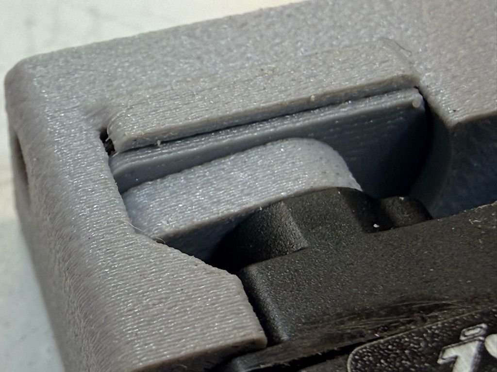
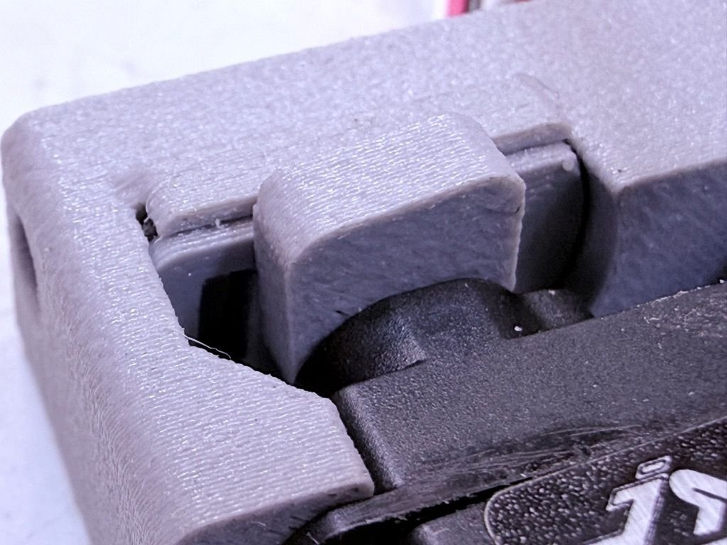
the effort has been to try to get the required flow (about the area of a 2.5mm hole at max) over a full 90 degrees of servo travel. Testing shows a fairly benign criticality though as the bleed seems to have some range of acceptable setting throughout except very close to closed throttle
Getting smaller
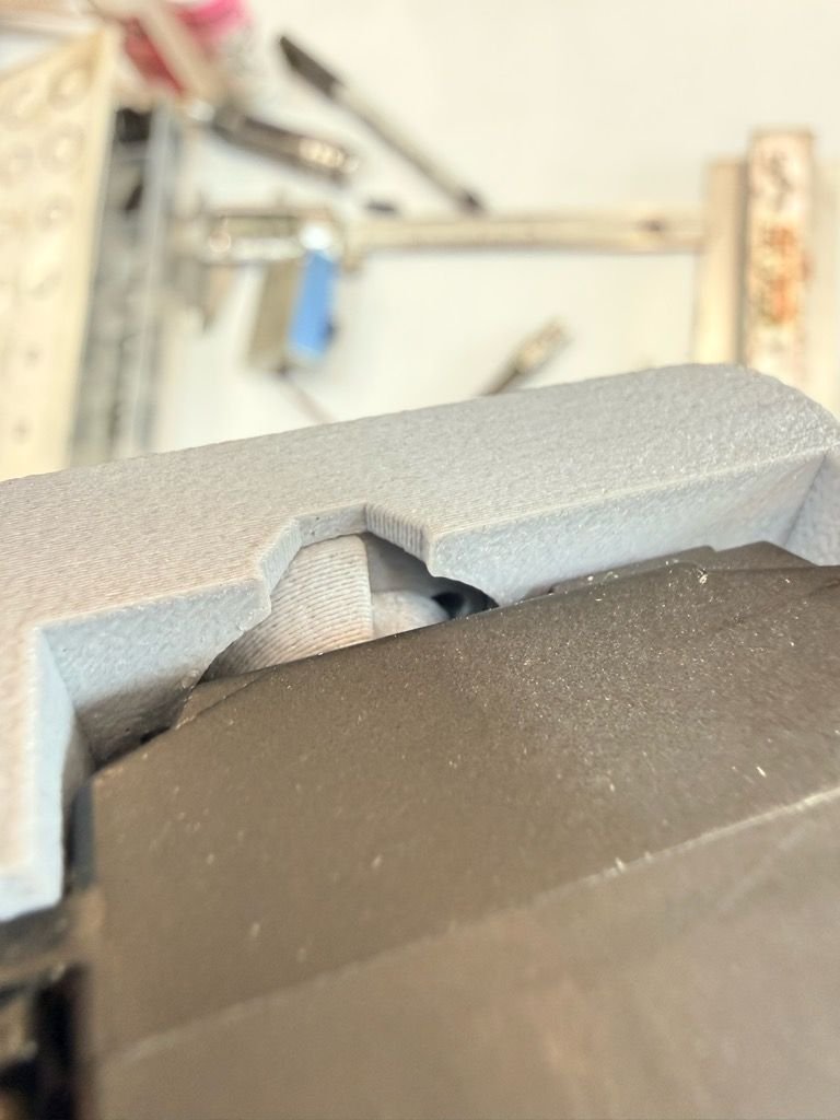
Valve half open
Send me a drawing when you can as I tend to get stuck on an idea when there are many ways to solve this. My earlier ones are what I would call a plug valve but maybe you have a different idea. I like this latest version and it seems to work well. It can also be made smaller or bigger easily if needed. I can print square holes and plugs but the biggest limitation with all this is print orientation. A square hole is trouble if it�s horizontal. (Support for the roof).
the effort has been to try to get the required flow (about the area of a 2.5mm hole at max) over a full 90 degrees of servo travel. Testing shows a fairly benign criticality though as the bleed seems to have some range of acceptable setting throughout except very close to closed throttle
Getting smaller
Valve half open
02-09-2026 | 11:32 PM
#2734
This is a mini servo�only because I don�t have a micro with what I would call good resolution. It�s smaller than the first version.
Send me a drawing when you can as I tend to get stuck on an idea when there are many ways to solve this. My earlier ones are what I would call a plug valve but maybe you have a different idea. I like this latest version and it seems to work well. It can also be made smaller or bigger easily if needed. I can print square holes and plugs but the biggest limitation with all this is print orientation. A square hole is trouble if it�s horizontal. (Support for the roof).
the effort has been to try to get the required flow (about the area of a 2.5mm hole at max) over a full 90 degrees of servo travel.Testing shows a fairly benign criticality though as the bleed seems to have some range of acceptable setting throughout except very close to closed throttle
Getting smaller
Valve half open
 yeah, size is different to judge in pics, I was going by the assumption that 4 attachment lugs meant a standard size servo, as most my smaller ones only have 2...
On the bolded, I would think that a progressive opening aperture could make the area near idle less critical? Something like a triangular opening in the valve plug against a circular opening in the housing?
Just thinking out loud here.
Normally plug and housing having both a round aperture, results in a very regressive opening characteristic, and even a theoretically linear shape, like "square on square" is not as linear as it seems, despite the flow-area is mathematically linear to opening angle.
But a triangular opening is not suitable for a plugtype, that would be more fitting for your earlier linear slide valve design.
I'll have to think about that...
02-10-2026 | 09:17 AM
#2736
02-10-2026 | 07:11 PM
#2737
My Feedback: (1)
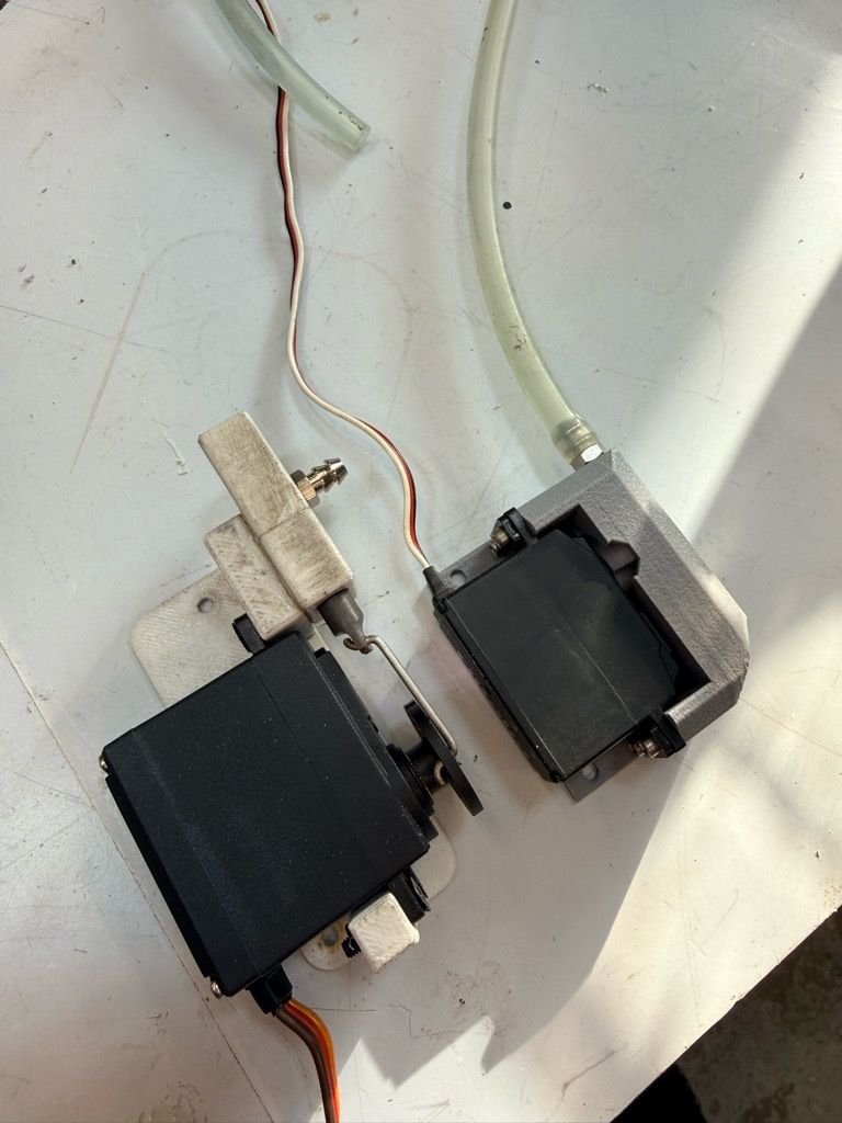
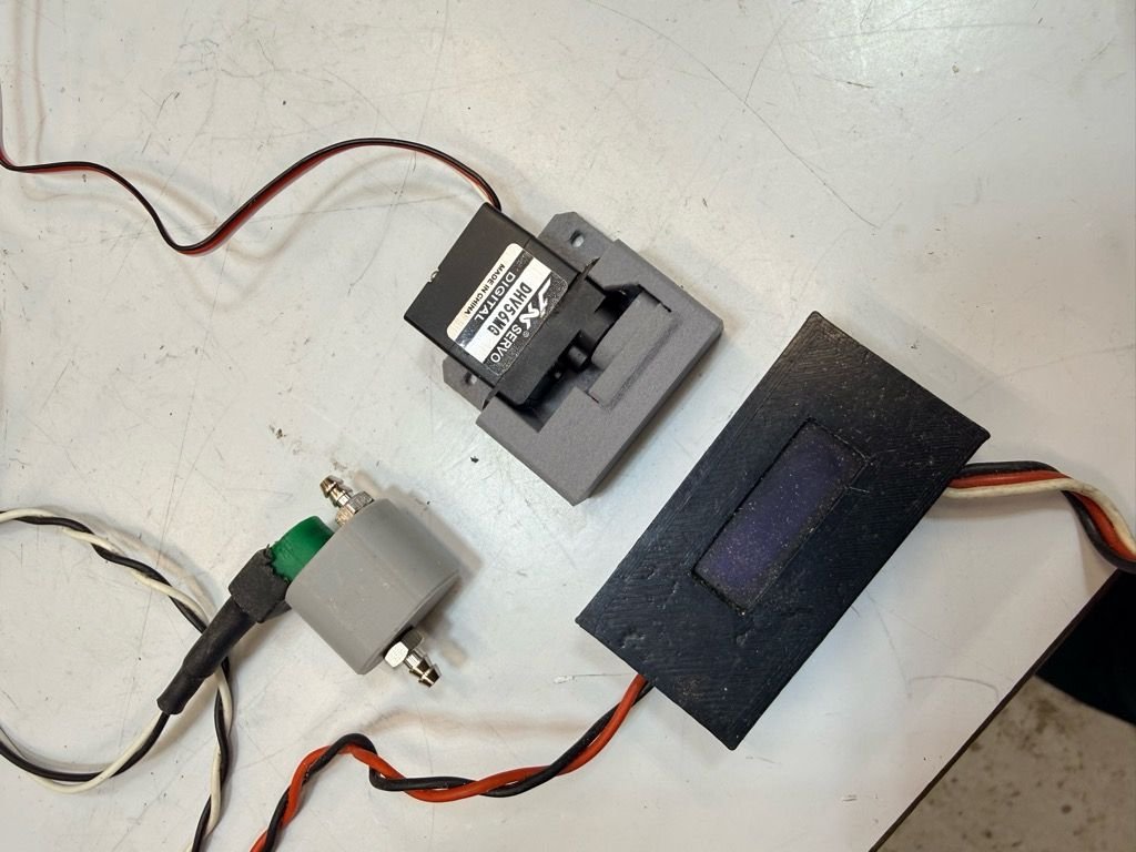
Here we go... The baby is born and it works well in function tests. Seals really well and is very smooth in operation. Size comparison to other versions and the solenoid and control box setup.. The shape of the square hole (visible in the one function picture) could be modified to change the opening characteristics. Just have to affix a hose nipple and will try to get this tested. In design it should flow the same amount (or more) as the first version.


02-11-2026 | 09:32 AM
#2738
My Feedback: (1)
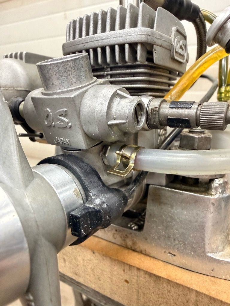
So micro works just as well as big brother... The "system" seems very uncritical. I ran the 91 4 stroke and a 37 two stoke and both set up with very quick tunes to be quite good on bench run. The Air is injected on the .37 by replacing one of the carb screws with a nipple as shown.
02-11-2026 | 11:51 PM
#2739
Cat, that's a really great solution! I love Bert's solenoid, but it requires more electronic modifications (and I've already had two Xiao solenoids fail after my plane was in storage for a long time, I don't know why). I'm currently assembling a Spacewalker with an ASP FS61, and I'm going to try your air bleed system on it. It's such a simple and easy solution! Well done!
02-12-2026 | 06:41 AM
#2740
WOW! I really am impressed how this solution seems to be repeatable and especially how this setup seems to eliminate the need for throttle delay.
Also VERY pleased with that solution for the air injection on the 2stroke.
Not even going to do an effort for an alternative design, for reason it won't be any more compact than what you allready have, NOR do I see any improvement from what I had in mind.
Can't wait for the flight tests!
Also VERY pleased with that solution for the air injection on the 2stroke.
Not even going to do an effort for an alternative design, for reason it won't be any more compact than what you allready have, NOR do I see any improvement from what I had in mind.
Can't wait for the flight tests!
02-12-2026 | 06:44 AM
#2741
Cat, that's a really great solution! I love Bert's solenoid, but it requires more electronic modifications (and I've already had two Xiao solenoids fail after my plane was in storage for a long time, I don't know why). I'm currently assembling a Spacewalker with an ASP FS61, and I'm going to try your air bleed system on it. It's such a simple and easy solution! Well done!
The FS91 will provide close to unlimited vertical (not fully unlimited) and result in a much more lively semi-aerobatic performance.
I am a bit baffled by your solenoids failing. I still have to replace the first one I installed (coincidentally the one in my own SpaceWalker
), now almost 7 years ago. Several of them have been in storage for periods over 2 or 3 years because I have often-used alsd less-often used planes, unavoidable once the fleet gets large enough.
Last edited by 1967brutus; 02-12-2026 at 06:49 AM.
02-12-2026 | 09:45 AM
#2742
Hi Bert, yes it's the first spacewalker from seagull of year 1999 I think.
Wingspan is 160cm, and normally it's for a 52 fs.
I hope my 61 fs converted is enough, if not I will change for the 91 fs.
The solenoid controller from you never failed, but the others I make with seeeduino Xiao failed randomly after a storage, I don't know why.
My air bleed valve :


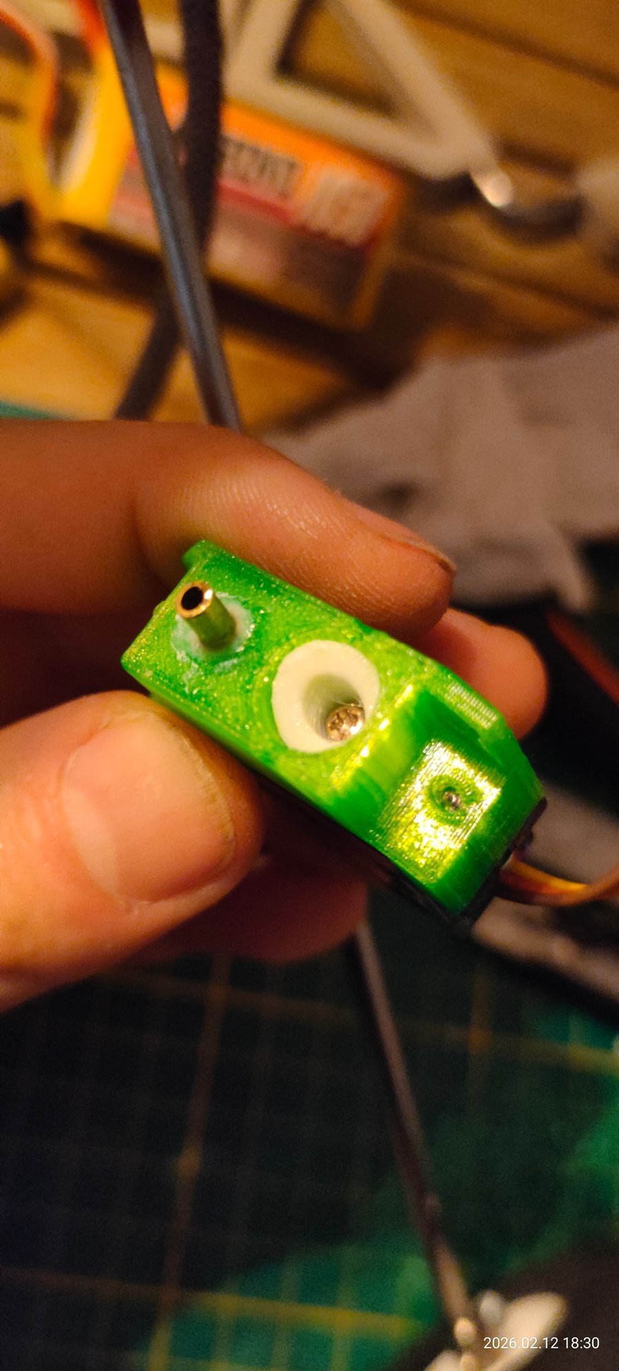
Engine test tomorrow if the weather is ok.
Wingspan is 160cm, and normally it's for a 52 fs.
I hope my 61 fs converted is enough, if not I will change for the 91 fs.
The solenoid controller from you never failed, but the others I make with seeeduino Xiao failed randomly after a storage, I don't know why.
My air bleed valve :
Engine test tomorrow if the weather is ok.
02-12-2026 | 10:35 AM
#2743
Mine is the one from VQ if I am not mistaken, but AFAIK it is the same. MIne is something like 155 cm or so, just a touch over 1,5 metre anyway. Weighs in at about 2,6 kilo, mine, and it does very nice on an FS91 and a 14 x 6 prop. Strictly talking gasoline conversion, of course, on MEthanol a .70 fourstroke would be enough and an 80 would already start to get ridiculous.
But with gasoline conversions, it's the old adage of "nothing substitutes cubic inches", and the 91 is the way to go.
Don't worry, it will most definitely fly with the 61, even on gasoline. Just not very powerful...
But with gasoline conversions, it's the old adage of "nothing substitutes cubic inches", and the 91 is the way to go.
Don't worry, it will most definitely fly with the 61, even on gasoline. Just not very powerful...
02-12-2026 | 10:50 AM
#2744
I do not know why Seeeduino electronics fail, I have heard once or twice that Hans' electronics failed, but that always turned out to be accidental short-circuits or reversed polarity issues, never from just storage.
It could have to do with the memory of Seeduino processors being volatile, perhaps? Did you try re-programming (flashing?) them? just a suggestion.
Anyway, the valve that Chris came up with, would really solve the entire issue, and make things MUCH more affordable. Both financially (which is NOT the main issue) but much more important, technically.
Anyone can improvise a small servo-operated airvalve even with oldfashioned materials.
I mean, if I had to, I could make one out of a tiny block of wood, a piece of 2,5 mm internal diameter brass tubing and basically an old rusty nail ground to a cone shape. Wouldn't look nice, wouldn't be compact, but it WOULD most definitely function.
And THAT is what I like most about Chris' new idea!
The downside is that it does not have the atmospheric compensation, which I particularly liked for keeping the planes cleaner, but that is a very small price to pay for the accessibility of this design.
02-12-2026 | 11:14 AM
#2745
It's the bootloader that become corrupted in the Seeeduino. I have to rewrite the bootloader with an ST Link v2, then rewrite the solenoid program, and it finally works again. But it's boring.
02-12-2026 | 11:46 AM
#2746
02-12-2026 | 08:42 PM
#2748
My Feedback: (1)
Great Alternate design MK... There are many ways to skin this cat I think, And Bert is correct that you could make one out wood if you needed to.
I really wish it wasn't winter here and I could get out and try this - I have an idea to get it into a plane but the weather might not cooperate. I will soon be ready as soon as I have a nice day. I tested a plane last week but the trek though hip deep snow wore me out.
I do not think this will replace the solenoid setup for accuracy - You can tell by the vague response to curve adjustments that this is more a correction not a setting. I'm thinking if you have a good running glow engine with a reasonably good carb (accurate needles) - this will allow it to run well on gas. It seems to correct the issue of the "thick mid range" very well.
Just a note - My "systems" use the bigger size tube and nipples (ID of nipple is 2.5MM) - This was determined to be minimum size needed in initial "open" hole tests. - But your results may vary......
02-13-2026 | 01:31 AM
#2749
Great Alternate design MK... There are many ways to skin this cat I think, And Bert is correct that you could make one out wood if you needed to.
I really wish it wasn't winter here and I could get out and try this - I have an idea to get it into a plane but the weather might not cooperate. I will soon be ready as soon as I have a nice day. I tested a plane last week but the trek though hip deep snow wore me out.
I do not think this will replace the solenoid setup for accuracy - You can tell by the vague response to curve adjustments that this is more a correction not a setting. I'm thinking if you have a good running glow engine with a reasonably good carb (accurate needles) - this will allow it to run well on gas. It seems to correct the issue of the "thick mid range" very well.
Just a note - My "systems" use the bigger size tube and nipples (ID of nipple is 2.5MM) - This was determined to be minimum size needed in initial "open" hole tests. - But your results may vary......
I really wish it wasn't winter here and I could get out and try this - I have an idea to get it into a plane but the weather might not cooperate. I will soon be ready as soon as I have a nice day. I tested a plane last week but the trek though hip deep snow wore me out.
I do not think this will replace the solenoid setup for accuracy - You can tell by the vague response to curve adjustments that this is more a correction not a setting. I'm thinking if you have a good running glow engine with a reasonably good carb (accurate needles) - this will allow it to run well on gas. It seems to correct the issue of the "thick mid range" very well.
Just a note - My "systems" use the bigger size tube and nipples (ID of nipple is 2.5MM) - This was determined to be minimum size needed in initial "open" hole tests. - But your results may vary......
-whether fuel draw will hold up in flight in the midrange throttle positions,
-whether location of the air injection valve in the plane will affect its accuracy and settings (does the airvalve need to be in the engine bay to be exposed to the same conditions as the main intake, or can it be in a more protected location behind the firewall)
-Is the valve subject to wear or pollution (does it "hold its calibration")?
To be honest, I won't be able to get around to experimenting with this very soon, but I have at least one plane with an engine where this is very easy to install (my ASP FS91 has a factory made port in the intake header), but that is one of the engines that also still has a carb that I modified by grinding the slanted groove in the throttle barrel. It would need a new unmodified carb to make the tests valid, and I don't have one.
02-13-2026 | 04:41 AM
#2750
I just tested the OS FS 61 with the controlled air bleed.
First, I adjusted the engine at full throttle with the main needle, then I found the optimal idle and transition points with the secondary needle. Next, I tried to improve the entire range with the air bleed. I can see a change in engine speed when opening or closing the air vent, but in my case, the improvement wasn't very noticeable. So I tried the engine with the entire air bleed system removed, and I must say that this engine runs quite well on gasoline with electronic ignition, and that's all. So I'm going to try a flight like this and see if there's a need to reinstall an controlled air bleed or solenoid system.
Do you think a linear valve (from aquarium?) controlled by a servo, on the fuel line, could works like Bert's solenoid but with the simplicity of Cat's air bleed?

