


Electronic solutions to modifying glow engines of all sizes to gasoline
 04-05-2026 | 05:16 AM
#2976


For the Saito CDI the information indicates it is expecting an AC signal from the induction trigger and a hall sensor produces a DC signal. I’m not sure I believe AI so more research is needed.
I am sorry you are having trouble with the air bleed system. What inconsistencies are you experiencing?
I am sorry you are having trouble with the air bleed system. What inconsistencies are you experiencing?
 04-05-2026 | 06:06 AM
#2977

My Feedback: (1)
Sorry I have been absent from the discussion. - My "system" does not notify well of thread updates and if i forget to come back and check I miss a lot of content. I see you fella's have been busy 
On the Saito 72 - Can you get reliable idle and top end settings with no bleed air flow. If not check the system for leakage - a tiny bit is acceptable (even preferred) as it keeps the bleed clear of fuel buildup. too much would make setup hard. Looking at the valve it might be a bit restrictive when open. The valve needs to flow the full unresticted flow of the feed line on most of my setups. I think I might also be one size bigger in feed line on the 90 I have running well. My cheat for this would be - if you have a good idle - unhook the valve and pinch the end of the line - advance the throttle to a bit less than half and see if you can adjust the pinch to make it run well at that setting - if the line is wide open and your still rich - more air is needed.
hope this makes sense.
Chris
On the Saito 72 - Can you get reliable idle and top end settings with no bleed air flow. If not check the system for leakage - a tiny bit is acceptable (even preferred) as it keeps the bleed clear of fuel buildup. too much would make setup hard. Looking at the valve it might be a bit restrictive when open. The valve needs to flow the full unresticted flow of the feed line on most of my setups. I think I might also be one size bigger in feed line on the 90 I have running well. My cheat for this would be - if you have a good idle - unhook the valve and pinch the end of the line - advance the throttle to a bit less than half and see if you can adjust the pinch to make it run well at that setting - if the line is wide open and your still rich - more air is needed.
hope this makes sense.
Chris
The following users liked this post:
xanaphyst (04-05-2026)
04-05-2026 | 10:07 AM
#2978

Following along so far...
I have this engine on a 1/5 cub with a solenoid and it runs great.
I have this engine on a 1/5 cub with a solenoid and it runs great.
Today I gave the Saito 72 its first run on gas. I probably should have ran it hard on glow fuel for a few min to get it warmed up and the old oil blown out. It also has new bearings that aren’t broken in. The initial start and run was tough to get settled in but it has cleaned up a lot now. It runs better and better as it builds time.
I can’t believe how clean the exhaust is. No smoke and no nasty oil slick !!!
Transition is pretty rough as expected.
Now I just need to figure out my injector housing solution.

I can’t believe how clean the exhaust is. No smoke and no nasty oil slick !!!
Transition is pretty rough as expected.
Now I just need to figure out my injector housing solution.
04-05-2026 | 01:38 PM
#2980
My Feedback: (1)
No Paul, I have only applied this method to two needle carbs. Basically I tune for Best Idle and Best top end and then apply the bleed to correct mid range. As with any two needle setup (glow or gas) there sometimes has to be some playing with both ends as there is what I call "interference" between the settings and sometimes it takes a bit of time to get both right. The Progressive metering of the fuel that the two needle does should be rich at midrange if a glow carb is run on gas and this is what the additional (and quite large) bleed corrects. Although i have not tried it, I think an air bleed is missing the critical low speed metering that would make this work - I think it would be hard to find an acceptable setting that would allow enough air to bring the mixture into line without affecting the both the RPM (increase) and carb throat suction (low- or none). That said I have not tried it.
04-05-2026 | 02:34 PM
#2981
My brother is working on an ignition advance circuit for my Stirlingkit CDI. It is actually a retard system because you program a delay from the top advance degree you start with. We will be starting with 28 degrees BYDC. He is going to start with a linear curve probably from 6 degrees at 1,000 rpm up to 28 degrees at about 7,000 rpm. It will stay at 28 degrees for any rpm above 7,000. He is going to have it connected to your phone so you can see the rpm’s and the timing number and he’s going to make it so you can
adjust the timing also by using your phone. I know this is like reinventing the wheel but it should be different because of your ability to change the timing curve.
On another note is do you think using a larger prop would help with getting a stable idle? I think I remember that converting to gas enables you to lug the engines without causing a problem.
adjust the timing also by using your phone. I know this is like reinventing the wheel but it should be different because of your ability to change the timing curve.
On another note is do you think using a larger prop would help with getting a stable idle? I think I remember that converting to gas enables you to lug the engines without causing a problem.
Virtually ANY engine I know, including my two bikes, have full advance slightly below 4K, but 4K is absolutely acceptable.
I wouldn't be me, if I did not have a vid of that

What you see is a stroboscope lighting the prop (vid was taken at dusk, hence poor image quality, but in broad daylight the strobe-light was not powerful enough).
Last edited by 1967brutus; 04-05-2026 at 02:36 PM.
04-05-2026 | 04:11 PM
#2982
Since I will be able to adjust the timing I appreciate your input. I read somewhere that at higher rpm’s the timing should retard a little from the 28 degrees. Any thoughts on that? Thanks
04-05-2026 | 04:20 PM
#2983
Chris. If you have an engine with the air bleed carb can you try it? The less expensive OS engines have the air bleed carbs.
If you close the air bleed screw on those carbs then you only have fuel coming from the main needle valve. I’m not saying this well. I understand that even with a two needle carb the fuel only comes from the main needle valve but I think your air bleed device could work better than the carbs air bleed screw and make those carbs usable. I haven’t built your air bleed device and I’m light years behind you with experience. If you get a chance to try it I would appreciate it. Thanks
If you close the air bleed screw on those carbs then you only have fuel coming from the main needle valve. I’m not saying this well. I understand that even with a two needle carb the fuel only comes from the main needle valve but I think your air bleed device could work better than the carbs air bleed screw and make those carbs usable. I haven’t built your air bleed device and I’m light years behind you with experience. If you get a chance to try it I would appreciate it. Thanks
04-05-2026 | 04:25 PM
#2984

This is the proposed phone screen my brother is building for me to adjust ignition timing. You can’t see the bottom of the screen. This would enable me to change ignition timing while the engine is running as long as you are near the device.
04-05-2026 | 04:29 PM
#2985
The above post was for my brother’s ignition timing system. Disregard the numbers shown on the screen for now. Those all can be modified to whatever is needed. When it’s working you will be able to see the engines rpm and the corresponding ignition timing. I’m not sure when he can complete this but I am anxious to try it out.
04-05-2026 | 06:09 PM
#2986
What they did, was to start retarding ignition at the RPM coinciding with the "tune" of the exhaust. This raised exhaust gas temperature significantly, and acoustically, a higher exhaust gas temperature "shortens the pipe". This effect widened the RPM range in which the exhaust was in tune.
Not by much, but in racing, every advantage is appreciated.
Our engines are pretty high revving as it is, but since they are designed for methanol, the hotter running gasoline allready maxes out the engines cooling capacity. A tuned pipe is not something I would reccommend, and retarded timing at high RPM only makes things more critical.
We gotta keep in mind that we are doing stuff the engines never were intended for.
An exception might be the later square-head SuperTigres, they look, from a cooling POV, as if they were designed with a possible gasoline option in mind. But I never explored that route.
04-06-2026 | 04:24 AM
#2987
Nope... That was actually done in 2-stroke racing, but has no place in our stuff.
Thanks. Good information to know. I’m have to figure out how you quote sections from one post and add it to your post.
Thanks. Good information to know. I’m have to figure out how you quote sections from one post and add it to your post.
 04-06-2026 | 07:10 AM
#2989
there literally is a "quote" button at the bottom of each post, click that and that post will in its entirety be added to your answer.You can edit the quoted part at will. Usually I only delete the non-relevant stuff, or highlight the adressed part by bold-printing or underscore if the rest is needed for context. Just be carefull not to CHANGE anything the other guy said, some folks frown on that.
Otherwise, pretty straightforward.
04-06-2026 | 07:23 AM
#2990
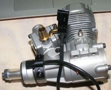
Oh, they do run quite nice indeed, and they have quite liberal power surplus for a 1/6th scale Cub. Easy to start, and fairly easy to get decent needle settings.
They just are severely underwhelming in performance given their displacement. If I had to guess you probably are running an 110 x 6 prop? In case of APC I would expect to see 9500 RPM, a Master Airscrew of that size maybe 10K
They produce, in reality, barely half a horse, while they should be, given the displacement, delivering at least 0,8~0,9 horseys.
Just as a comparison, my ASP 52 fourstrokes, slightly smaller in displacement, allready deliver that power, and my .46 2-strokes (significantly less displacement than the NGH9) outperform them by about 30%.
A bit less torque-ey maybe, so a smaller prop, but significantly more horsepower.
Planes fly solely on HP, they do not care about torque.
They just are severely underwhelming in performance given their displacement. If I had to guess you probably are running an 110 x 6 prop? In case of APC I would expect to see 9500 RPM, a Master Airscrew of that size maybe 10K
They produce, in reality, barely half a horse, while they should be, given the displacement, delivering at least 0,8~0,9 horseys.
Just as a comparison, my ASP 52 fourstrokes, slightly smaller in displacement, allready deliver that power, and my .46 2-strokes (significantly less displacement than the NGH9) outperform them by about 30%.
A bit less torque-ey maybe, so a smaller prop, but significantly more horsepower.
Planes fly solely on HP, they do not care about torque.
04-06-2026 | 09:29 AM
#2991
My Feedback: (1)
Chris. If you have an engine with the air bleed carb can you try it? The less expensive OS engines have the air bleed carbs.
If you close the air bleed screw on those carbs then you only have fuel coming from the main needle valve. I’m not saying this well. I understand that even with a two needle carb the fuel only comes from the main needle valve but I think your air bleed device could work better than the carbs air bleed screw and make those carbs usable. I haven’t built your air bleed device and I’m light years behind you with experience. If you get a chance to try it I would appreciate it. Thanks
If you close the air bleed screw on those carbs then you only have fuel coming from the main needle valve. I’m not saying this well. I understand that even with a two needle carb the fuel only comes from the main needle valve but I think your air bleed device could work better than the carbs air bleed screw and make those carbs usable. I haven’t built your air bleed device and I’m light years behind you with experience. If you get a chance to try it I would appreciate it. Thanks
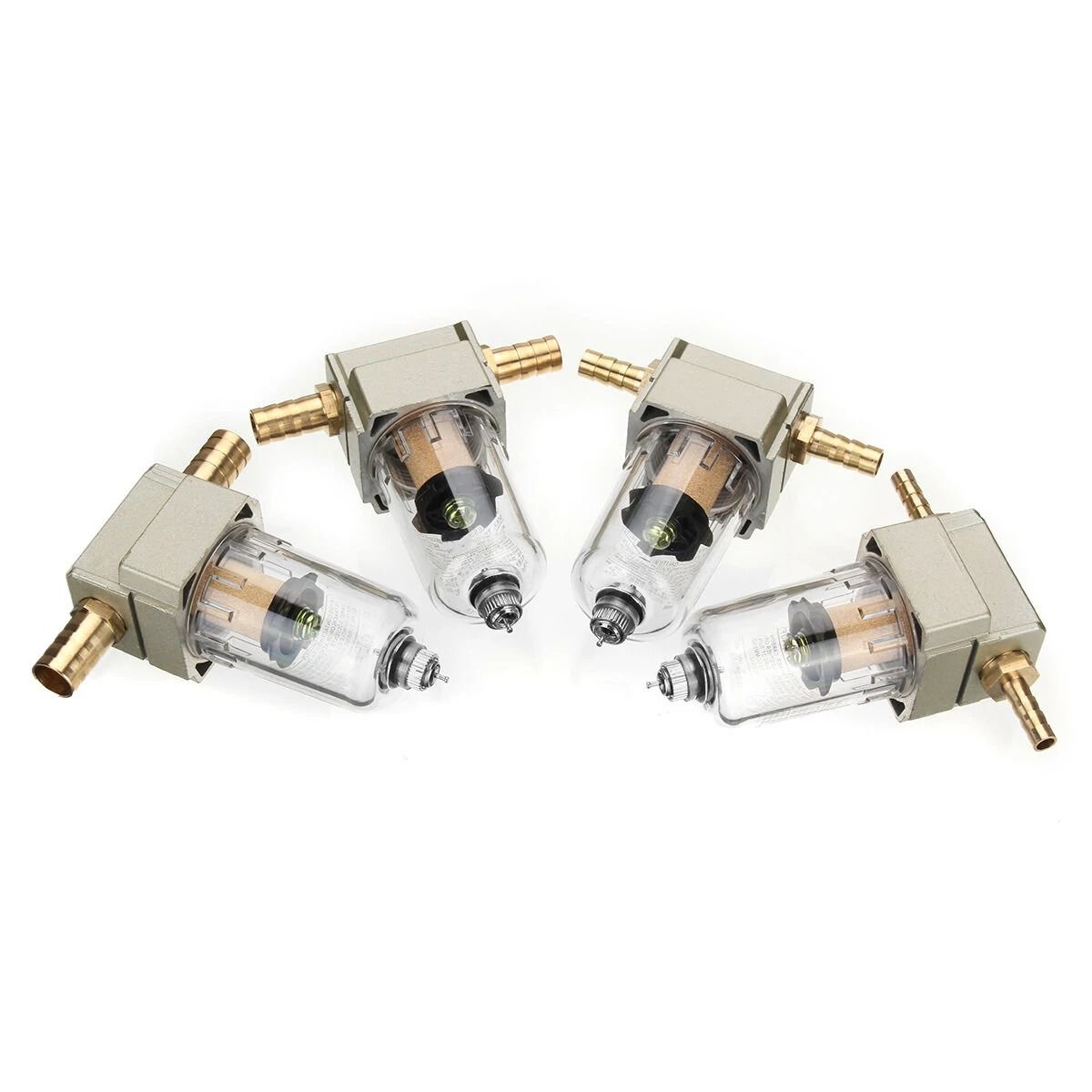
I will look to see if i have anything that would be simple to set up and give it a try.
 04-06-2026 | 11:07 AM
#2993
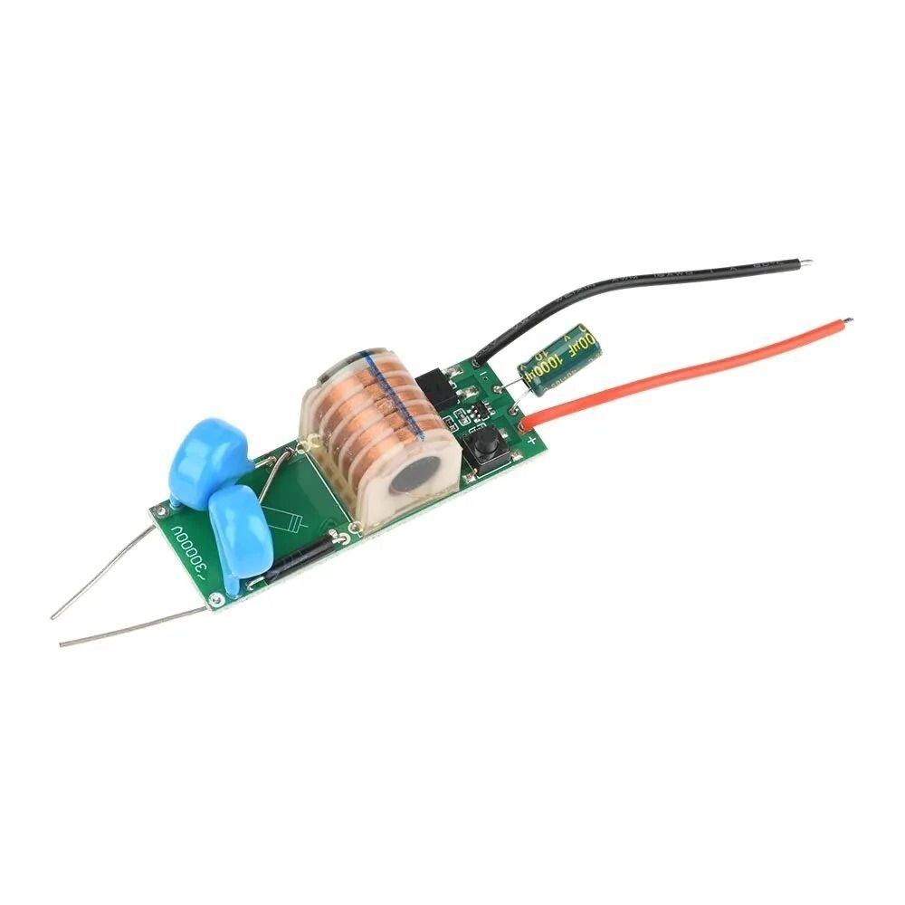
 Sparks for homebrew cdi?
Generates high voltage.
The switch pulls a pin high so a esp or other controller should be able to switch that.
Would recommend to cast it in epoxy (potting) to make it last longer and place it into a metal case for shielding.
scroll down on the product page for schematics.
https://www.banggood.com/High-Voltag...ElectronicsPop
The switch pulls a pin high so a esp or other controller should be able to switch that.
Would recommend to cast it in epoxy (potting) to make it last longer and place it into a metal case for shielding.
scroll down on the product page for schematics.
https://www.banggood.com/High-Voltag...ElectronicsPop
04-06-2026 | 11:21 AM
#2994
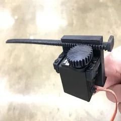
servo link geometry ?
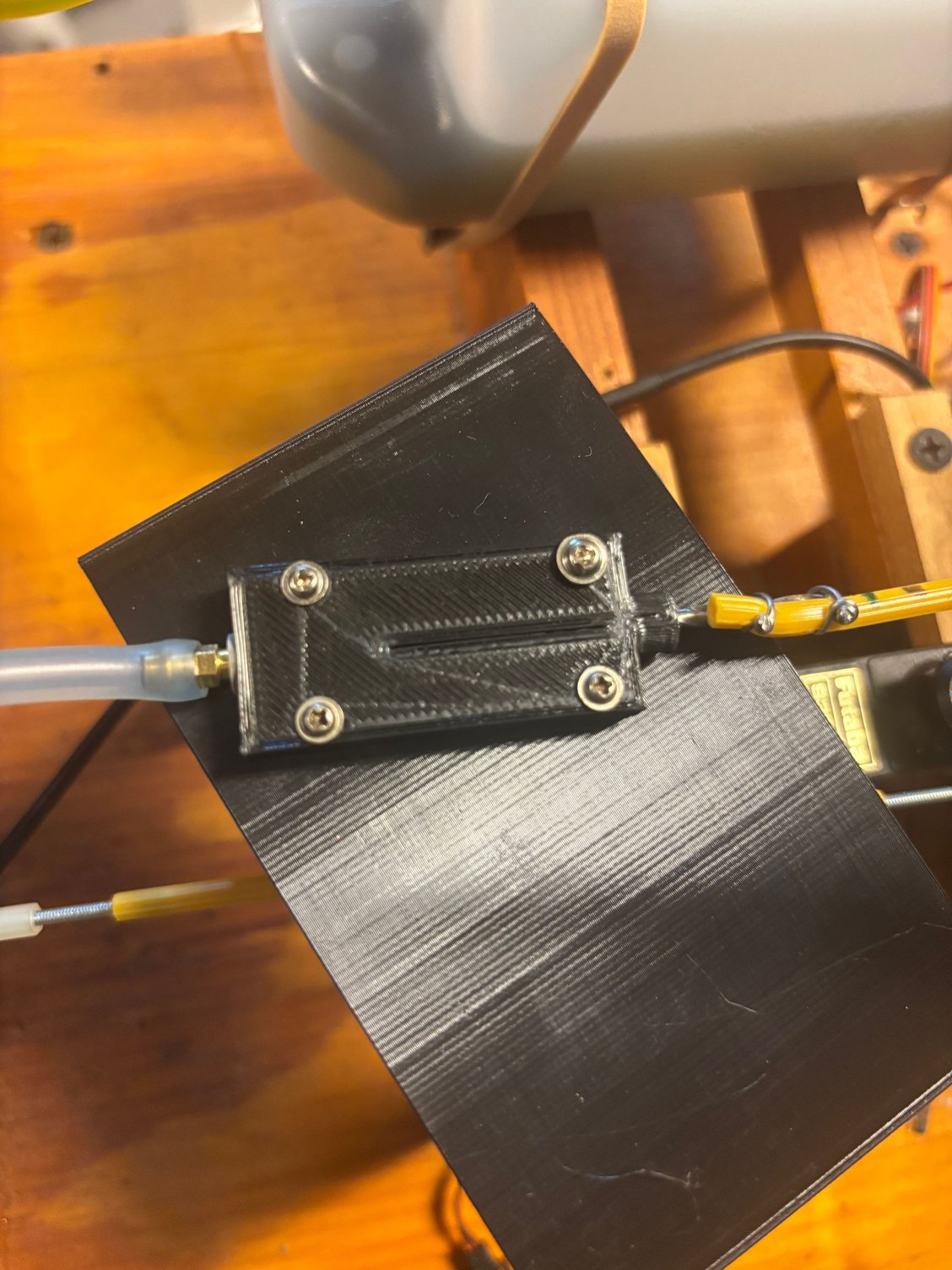
You get more movement when the push-rod is at 90degrees and less at the other extremes of the deflection,
In a way you are mixing (mechanically) a additional "curve" on top of the transmitter programed curve.
If you like 3d printing then a "rack and pinion" setup on the servo will make the servo movement linear.
Ideally a small diameter pinion with fine teeth to get a high resolution.
examples:
https://www.printables.com/search/mo...q=lilear+servo
 04-06-2026 | 11:24 AM
#2995
 Good to know
04-06-2026 | 11:45 AM
Good to know
04-06-2026 | 11:45 AM
#2996
optimum speed
Very few model pilots take this into consideration. Each model design has a optimum speed; for example a piper cub model might go about 70 to 80 km/h
So to get best performance you want a prop pitch resulting in a "prop speed" (pitch times rpm) that is a little higher then the maximum speed you want the model to fly.
For a 6.5cc for example you might end up with a 11" by 5" prop on a piper cub while a pylon racer might run a 7.4" by 7.5"
The piper would end up with much more "static trust" then the pylon racer and take off in a shorter distance.
Trust and torque are related so it is still a factor to keep in mind.
04-06-2026 | 11:59 AM
#2997
How do you want to use the saito cdi?
So the cdi works as designed
The next step is to make it work for what you want to use it for,
Are there specific engines you want to use these cdi on?
For example; if the sensor case is just clipped shut it might be possible to take the coil out and mount it in a way that works for you.
It might even be able to pickup the crank-pin trough the back-plate like the futaba sensor (same design)
Then you would not even have to glue in a magnet in the prop driver. "just" make a holder that is bolted on with the back-plate screws.
The next step is to make it work for what you want to use it for,
Are there specific engines you want to use these cdi on?
For example; if the sensor case is just clipped shut it might be possible to take the coil out and mount it in a way that works for you.
It might even be able to pickup the crank-pin trough the back-plate like the futaba sensor (same design)
Then you would not even have to glue in a magnet in the prop driver. "just" make a holder that is bolted on with the back-plate screws.
04-06-2026 | 02:35 PM
#2998
I assume you did the same when controlling boat engines; make sure the prop pitch is chosen so that the ideal "hull speed" matches the optimum engine rpm.
Very few model pilots take this into consideration. Each model design has a optimum speed; for example a piper cub model might go about 70 to 80 km/h
So to get best performance you want a prop pitch resulting in a "prop speed" (pitch times rpm) that is a little higher then the maximum speed you want the model to fly.
For a 6.5cc for example you might end up with a 11" by 5" prop on a piper cub while a pylon racer might run a 7.4" by 7.5"
The piper would end up with much more "static trust" then the pylon racer and take off in a shorter distance.
Trust and torque are related so it is still a factor to keep in mind.
Very few model pilots take this into consideration. Each model design has a optimum speed; for example a piper cub model might go about 70 to 80 km/h
So to get best performance you want a prop pitch resulting in a "prop speed" (pitch times rpm) that is a little higher then the maximum speed you want the model to fly.
For a 6.5cc for example you might end up with a 11" by 5" prop on a piper cub while a pylon racer might run a 7.4" by 7.5"
The piper would end up with much more "static trust" then the pylon racer and take off in a shorter distance.
Trust and torque are related so it is still a factor to keep in mind.
It TILL is the engine delivering a certain amount of power to the gearbox input, and the gearbox converting that power to the desired torque and rpm for the prop.
For simplicity reasons, in RC flying we rarely if ever use reduction gears, so yes, it IS possible that a plane performs better with a larger slower prop, meaning the engine does not deliver its optimal horsepower, but then we are talking about prop-efficiency, and that is an altogether different animal. An animal that even I have only a rudimentary understanding of...
Maybe it is more accurate to say that planes fly on the horsepower as delivered by the prop...
04-07-2026 | 05:22 AM
#2999
So the cdi works as designed
The next step is to make it work for what you want to use it for,
Are there specific engines you want to use these cdi on?
For example; if the sensor case is just clipped shut it might be possible to take the coil out and mount it in a way that works for you.
It might even be able to pickup the crank-pin trough the back-plate like the futaba sensor (same design)
Then you would not even have to glue in a magnet in the prop driver. "just" make a holder that is bolted on with the back-plate screws.
The next step is to make it work for what you want to use it for,
Are there specific engines you want to use these cdi on?
For example; if the sensor case is just clipped shut it might be possible to take the coil out and mount it in a way that works for you.
It might even be able to pickup the crank-pin trough the back-plate like the futaba sensor (same design)
Then you would not even have to glue in a magnet in the prop driver. "just" make a holder that is bolted on with the back-plate screws.

