


Electronic solutions to modifying glow engines of all sizes to gasoline
 11-24-2022 | 07:39 PM
#1201

My Feedback: (1)
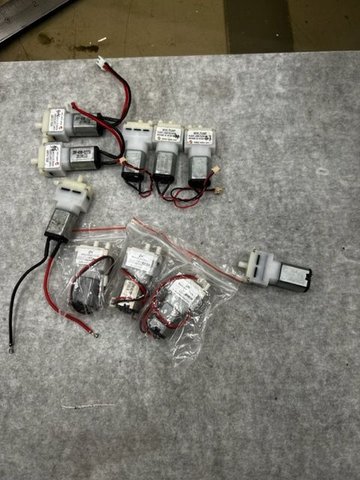
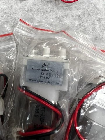
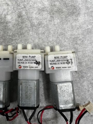
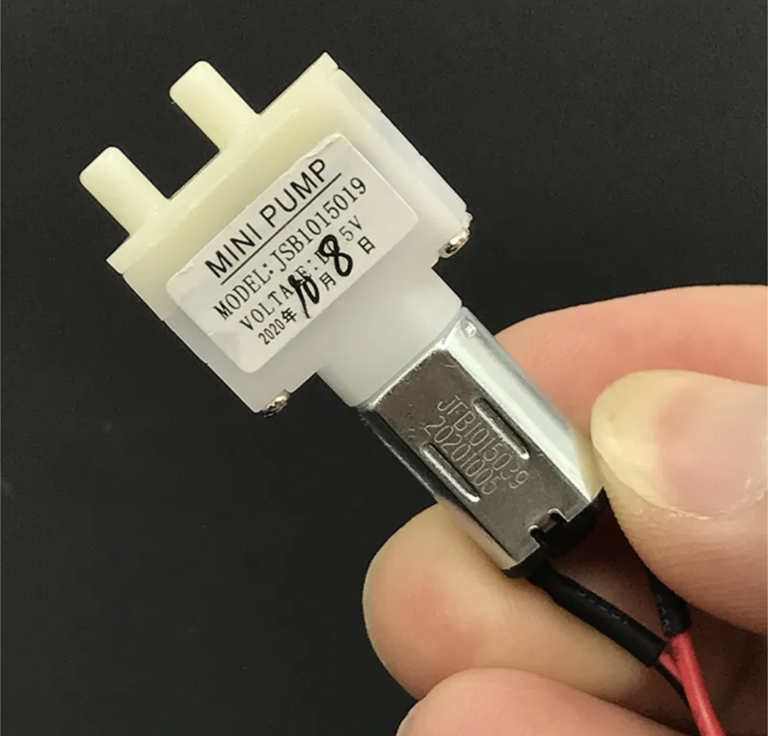
Package showed up today from overseas and had some air movers in it.. Have an assortment to play with of a few differ styles - One is even marked "water pump"...
Attaching a little video to show just how fast this system can react if needed - Just pumping into a closed and empty 4 oz tank. Using mbar to appease Bert - for our US followers 1 psi = 69 mbar I think the demo shows how quick it is. I then let the pump off scale the manometer (240 mbar)

Attaching a little video to show just how fast this system can react if needed - Just pumping into a closed and empty 4 oz tank. Using mbar to appease Bert
- for our US followers 1 psi = 69 mbar I think the demo shows how quick it is. I then let the pump off scale the manometer (240 mbar)

 11-25-2022 | 01:58 PM
#1203

Well you're almost there now, especially with the TBi carb... If you can get the air pump, and the solenoid driver / micro-controller & LCD in one box, that would be a nice compact package with minimal connections to be made... you could also put all the inputs/outputs wires on one multi-pin connector, that would make it that much cleaner, all depends on the model its going in of course... it probably wouldn't be any bigger than a CDi box.
Last edited by John_M_; 11-25-2022 at 02:00 PM.
11-25-2022 | 05:07 PM
#1204

I ordered 3 of these. Seems to be a bunch of different part numbers. I figured 5v could be powered from 2s life without a regulator since the solenoid and OLED is probably close to max on the onboard 3.3v supply.
11-26-2022 | 01:05 PM
#1205
hey chris. i read the new code you sent. i realize it is working for you at the moment but you're doing some things i did with the solenoid controller in its evolution.
i know you're using the air pump witout a solenoid at the moment. you're using 215 steps for the pump output. is there a reason you're not utilizing more steps?
have you tested to see how many steps are possible?
do you have plans to add air temperature and pressure compensation? if so, you're going to want more steps.
11-27-2022 | 06:50 AM
#1206
My Feedback: (1)
hey chris. i read the new code you sent. i realize it is working for you at the moment but you're doing some things i did with the solenoid controller in its evolution.
i know you're using the air pump witout a solenoid at the moment. you're using 215 steps for the pump output. is there a reason you're not utilizing more steps?
have you tested to see how many steps are possible?
do you have plans to add air temperature and pressure compensation? if so, you're going to want more steps.
i know you're using the air pump witout a solenoid at the moment. you're using 215 steps for the pump output. is there a reason you're not utilizing more steps?
have you tested to see how many steps are possible?
do you have plans to add air temperature and pressure compensation? if so, you're going to want more steps.
I am aware if the step restriction but for the development I just wanted to keep it simple - Because this is a less "precise" form of mixture control. My testing ( Viable DC power to pressure checks) showed a very corse but repeatable relationship. I decided to use the basic 0-255 PWM generation in the MPU. More steps might be better but I don't know if they would be required for the basic "tank pressure" with the solenoid setup. As you point out it might help when its used alone without the solenoid.
Here is what I know from testing - Bench only - a 10% output bias on the pump pulse width gets a "fine tuning" type response. I know with the solenoid this is a dramatic change. 10% on the pump is more line 1% on the solenoid.
Programming MPU's is a bit of black magic to me and I tend to keep stuff a simple as possible - The Timer functions and porting quickly go over my head. My code is usually snippets of simple code that I just mange to get to work together. Im sure you will be able to come up with much better. I do think if we can tie this all together into one board and package it right it will be a good setup.
11-27-2022 | 07:23 AM
#1207
Some hints for programming....
256 step pwm is standard on most arduinos. If you don't need higher resolution, there's no need to get into that low level timer stuff that I got into for the solenoid valve.
Timer pins come in pairs so I think there's a complimentary pin to the one I'm using for the solenoid that also has high resolution on the xiao. I'll eventually write some code and scope it and check.
I think you can plug an air pump into a solenoid controller to check if it can support the additional resolution. We should ultimately build these changes strollers with the ability to use the most resolution they have available even if it's not necessary in order to future proof the hardware.
I think a package with controller and air pump in one and plugs on that package for a solenoid and display would be an interesting design. The bmp280 might even be included in that package or it could be remote with the solenoid.
11-27-2022 | 09:17 AM
#1208
You could take the solenoid output signal pin on the MCU and loop it back through another input... in the sketch add your air pump loop, invert the signal out to another output pin to the air pump driver... then the air pump will follow the solenoid... air pressure will rise as the throttle is opened, and lower as the throttle is closed... it would mirror the mixture curve though.
***EDIT***
I take it you are using both the fuel solenoid valve along with the air pump... still using the solenoid to control the mixture, and the air pump to control the tank bias pressure?
***EDIT***
I take it you are using both the fuel solenoid valve along with the air pump... still using the solenoid to control the mixture, and the air pump to control the tank bias pressure?
Last edited by John_M_; 11-27-2022 at 09:26 AM.
11-27-2022 | 09:28 AM
#1209
I think the air pump wants to follow RPM. The solenoid doesn't follow RPM. I think I want several options for controlling the air pump. Without a solenoid present, I want it to read a channel and behave like the solenoid would. I also want to be able to add RPM as a controlling input for the air pump. Possibly the ability to select either or both on the fly.
11-27-2022 | 10:39 AM
#1211
If you have the air pump follow the mixture curve... invert the signal so when the solenoid driver output is high, the air pump driver output is low, and vise versa, you will have modulated tank bias pressure when the solenoid valve is open... Cat mentioned he was using another needle valve to set the bleed off pressure to the tank... so you would trim the tank bias pressure that way... Or if you wanted separate control over the air pump pressure bias curve, you'll have to setup the MCU & sketch with another PWM output, and another channel mix to set the pressure bias curve.
11-27-2022 | 10:46 AM
#1212
That's why I was going to explore using s.bus: as many channels as I want but solenoid mixture, throttle position, and a control channel or two. Controls could tune tank pressure, enable choke, tune an acceleration pump, etc. We could also add sequencing for things like starting
11-27-2022 | 11:36 AM
#1213
As long as you can mix 2 or more channels to the throttle channel, you can do anything with that XIAO... you can use a toggle switched channel to initiated the cold start fast idle sequence... build tank pressure, increase the solenoid duty cycle for cold enrichment, and increase engine idle rpm... With the 18SZ I can use the throttle channel as a throttle position reference only, I have to sacrifice the channel output without a servo connected, and then mix channels to control the throttle servo, and fuel mixture... and then mix in another channel to control the air pump... and then use a conditional mix to initiate some sort of start up sequence based on the rpm and cylinder head temp, etc, but I'm limited to what the futaba telemetry can provide, so I would have to resort to sensory inputs directly into the MCU.
11-28-2022 | 06:51 PM
#1214
My Feedback: (1)
I'm stuck up at one of our northern bases this week doing management coverage so no shop time this week.. but I want to share a couple of weekend items.
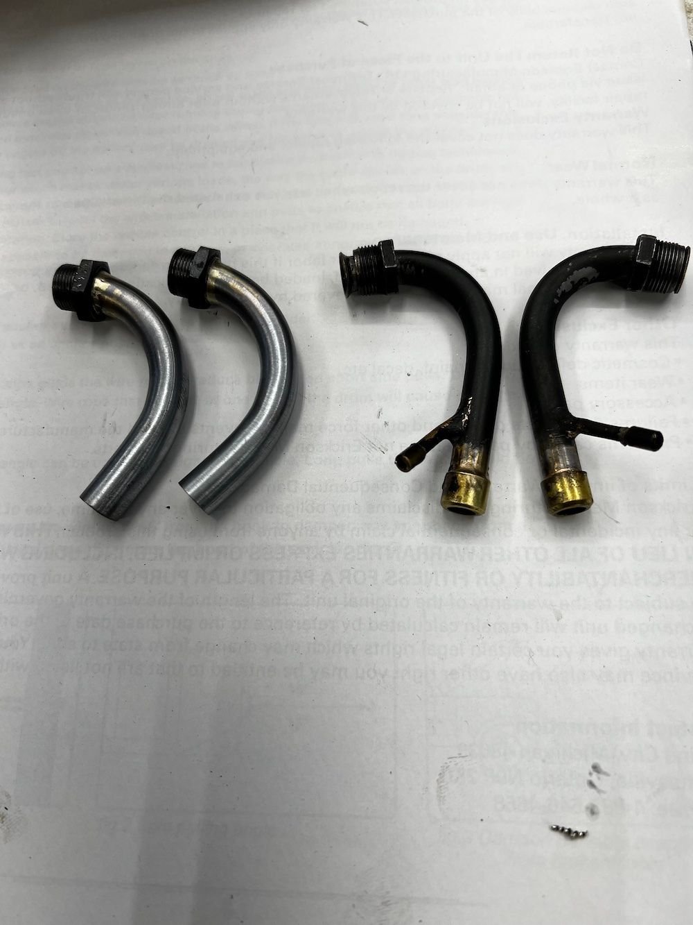
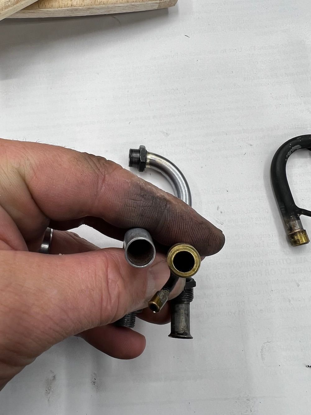
Because I plan to utilize the e-pump now on my Boxer setup I can free up the exhaust for better flow - so I made up a set of stacks to help with that.. My last set was 6.7 mm ID and I had to restrict then to about 6mm to get sufficient exhaust pressure to move fuel. The new ones are about 8mm ID made by having a "fixed" external thread and a jam nut rather than the compression fitting..

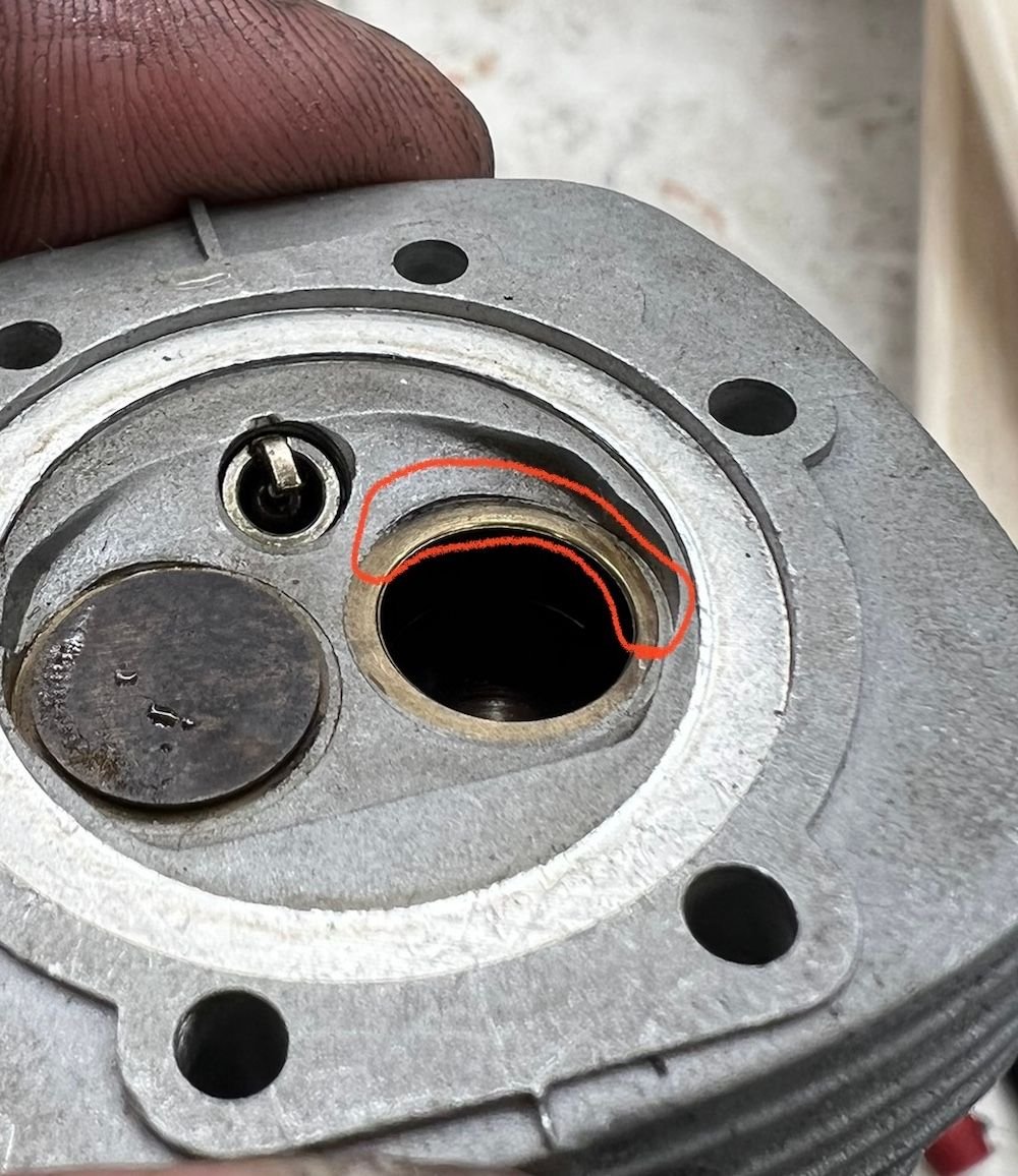
On another finding - I have always had "mushier" compression on one of the cylinders of this engine - I think Bert and Dave might have had similar issues.. Dave suggested I check for a stuck ring and I did that but found it OK - ring gap is a little excessive but nothing else is apparently bad there. As I was reassembling I tried to check all leak sources and noted the intake had a draw and pressure as it was turned over with the port plugged with a finger. (both valves closed) Took a while to find it but there is a leak between the valve seat and the head in the area noted in the picture. This engine runs excellent so I don't think its an issue and I don't think to would be a simple fix.
Because I plan to utilize the e-pump now on my Boxer setup I can free up the exhaust for better flow - so I made up a set of stacks to help with that.. My last set was 6.7 mm ID and I had to restrict then to about 6mm to get sufficient exhaust pressure to move fuel. The new ones are about 8mm ID made by having a "fixed" external thread and a jam nut rather than the compression fitting..
On another finding - I have always had "mushier" compression on one of the cylinders of this engine - I think Bert and Dave might have had similar issues.. Dave suggested I check for a stuck ring and I did that but found it OK - ring gap is a little excessive but nothing else is apparently bad there. As I was reassembling I tried to check all leak sources and noted the intake had a draw and pressure as it was turned over with the port plugged with a finger. (both valves closed) Took a while to find it but there is a leak between the valve seat and the head in the area noted in the picture. This engine runs excellent so I don't think its an issue and I don't think to would be a simple fix.
11-29-2022 | 12:31 AM
#1215
So the bronze valve seat insert is leaking around the head casing.... I believe the head is cast around those bronze seat inserts... I can't imagine the leak being that great around the casings when the engine is turned over by hand... but being a single piston ring, the excessive ring gap on the effected cylinder would cause a noticeable compression loss when turned over by hand, but at reciprocating piston speeds, the dynamic compression loss is less.
Valve seat face doesn't look uniform, maybe its just shadows... but you can use a mild abrasive toothpaste, or a pumas cleanser and lap the valve / seat faces.
Valve seat face doesn't look uniform, maybe its just shadows... but you can use a mild abrasive toothpaste, or a pumas cleanser and lap the valve / seat faces.
11-29-2022 | 12:48 AM
#1216
On another finding - I have always had "mushier" compression on one of the cylinders of this engine - I think Bert and Dave might have had similar issues.. Dave suggested I check for a stuck ring and I did that but found it OK - ring gap is a little excessive but nothing else is apparently bad there. As I was reassembling I tried to check all leak sources and noted the intake had a draw and pressure as it was turned over with the port plugged with a finger. (both valves closed) Took a while to find it but there is a leak between the valve seat and the head in the area noted in the picture. This engine runs excellent so I don't think its an issue and I don't think to would be a simple fix.
The engine ran perfectly fine with that...
 11-29-2022 | 06:05 AM
#1217
My Feedback: (1)
Valve seat is ok and valve seals well - Made a delrin plug and held it in with a 3mm cap screw though the guide. filled the head and small pressure on the port and bubbles showed it definitely coming from the seat /head interface. I think I'm just going to accept the fact that compression is mushy on this one as it runs so well. Might throw rings at it if I find some.
To Bert's item - its amazing what they will run with sometimes - Turbines are even better - we open up our little turboprops sometimes to do "hot section inspections" and find pure garbage - vanes all warped and cracked and eroded blades yet they preform right on the numbers in a performance check. Others that look pristine can struggle to make proper power. Dynamic gas flows can be tricky....
To Bert's item - its amazing what they will run with sometimes - Turbines are even better - we open up our little turboprops sometimes to do "hot section inspections" and find pure garbage - vanes all warped and cracked and eroded blades yet they preform right on the numbers in a performance check. Others that look pristine can struggle to make proper power. Dynamic gas flows can be tricky....
11-29-2022 | 07:28 AM
#1218
Valve seat is ok and valve seals well - Made a delrin plug and held it in with a 3mm cap screw though the guide. filled the head and small pressure on the port and bubbles showed it definitely coming from the seat /head interface. I think I'm just going to accept the fact that compression is mushy on this one as it runs so well.
It is a bit similar to how small cracks in car windshields are repaired. There they use UV to cure the resin, but that prolly won't work on more opaque parts like cylinder heads
11-29-2022 | 09:10 AM
#1219
Does it leak that much around seat edge?... small bubbles would indicate a seepage around the insert, but I'd be surprised if it caused any issue with the engine running... The only concern would be if its a shrunk in seat ring, then it could drop out, but usually they are cast in and are fully captured.
Try Berts suggestion, red loctite or the loctite Bearing retainer, which should wick in under a vacuum for sure, good idea actually.
Try Berts suggestion, red loctite or the loctite Bearing retainer, which should wick in under a vacuum for sure, good idea actually.
11-29-2022 | 11:55 AM
#1220
11-29-2022 | 05:57 PM
#1221
My Feedback: (1)
Brilliant idea Bert ... I think I have all the materials needed. Will document when do it. As John said I don't think its enough to really effect how the engine runs and I'm sure the seat will not fall out but it does effect the slow speed compression because of what I have observed with the intake port pressure fluctuation with the valve closed.
11-30-2022 | 12:17 AM
#1222
Brilliant idea Bert ... I think I have all the materials needed. Will document when do it. As John said I don't think its enough to really effect how the engine runs and I'm sure the seat will not fall out but it does effect the slow speed compression because of what I have observed with the intake port pressure fluctuation with the valve closed.
11-30-2022 | 04:29 AM
#1223
For sure, even worse if the casting void exits to the atmosphere, as it did on my friends Saito. His engine had a casting void from the intake port into the rocker box area. The thing would run different with the rocker cover on vs off. We pulled a mild vacuum on the intake port with a hand pump and drew in slightly thinned JBweld. I worked but I've lost track of him, probably still runs fine.
11-30-2022 | 04:51 AM
#1224
For sure, even worse if the casting void exits to the atmosphere, as it did on my friends Saito. His engine had a casting void from the intake port into the rocker box area. The thing would run different with the rocker cover on vs off. We pulled a mild vacuum on the intake port with a hand pump and drew in slightly thinned JBweld. I worked but I've lost track of him, probably still runs fine.
11-30-2022 | 10:16 AM
#1225
They use to cast in the entire valve seat and port as one piece out of bronze, saito's ABC was one, and I believe OS did the same with their early 4 strokes.
The OS 160 boxer uses a one piece interference fit bronze seat & Valve guide, pressed in from the combustion chamber side and then the ports are bored through the bronze afterwards.
The OS 160 boxer uses a one piece interference fit bronze seat & Valve guide, pressed in from the combustion chamber side and then the ports are bored through the bronze afterwards.
Last edited by John_M_; 11-30-2022 at 10:20 AM.

