


Highly Modified AK Models SU-27 Build Thread
 05-13-2006 | 11:23 PM
#26

Thread Starter
Senior Member
My Feedback: (1)
Joined: Jun 2005
Posts: 825
Likes: 0
Received 0 Likes
on
0 Posts
From: Antelope Valley,
CA
 RE: Highly Modified AK Models SU-27 Build Thread
Using a straight edge, drew center line 4 & 13/32" from the top of stab (25% of MAC) where I plan to embed the 9/32" brass tube on both sides of the stab (Figures 1 & 2)
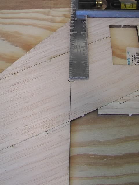
Figure 1
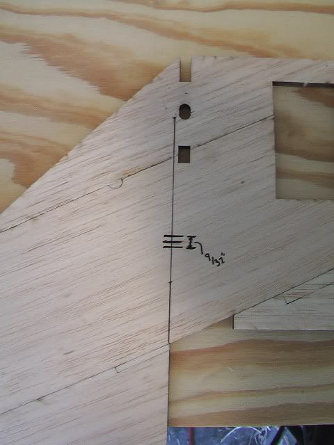
Figure 2
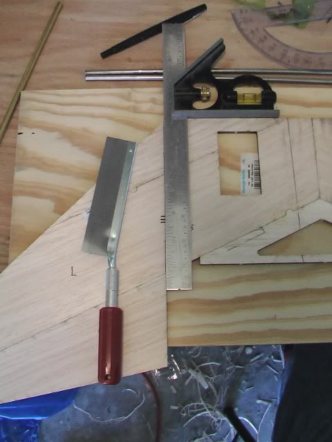
Next, I used a 90 degree square and ever so carefully cut the stabilator from the stab (Figure 3)
 ]
]
Figure 3
Then marked where the stab should be flush with the fuse (Figure 4)
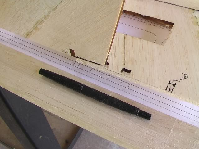
Figure 4
Figure 1
Figure 2
Next, I used a 90 degree square and ever so carefully cut the stabilator from the stab (Figure 3)
]Figure 3
Then marked where the stab should be flush with the fuse (Figure 4)
Figure 4
 05-13-2006 | 11:38 PM
#27
Thread Starter
Senior Member
My Feedback: (1)
Joined: Jun 2005
Posts: 825
Likes: 0
Received 0 Likes
on
0 Posts
From: Antelope Valley,
CA
RE: Highly Modified AK Models SU-27 Build Thread
Control Rod/Horn
Since the stabilator will only move 3/4"-1" I did not want or need the servo to be far from the control horn so I positioned it 1.5" from the servo arm (Figure 1). This coupled with 1/8" push rods (for the stabilator) will reduce the chance of flutter.
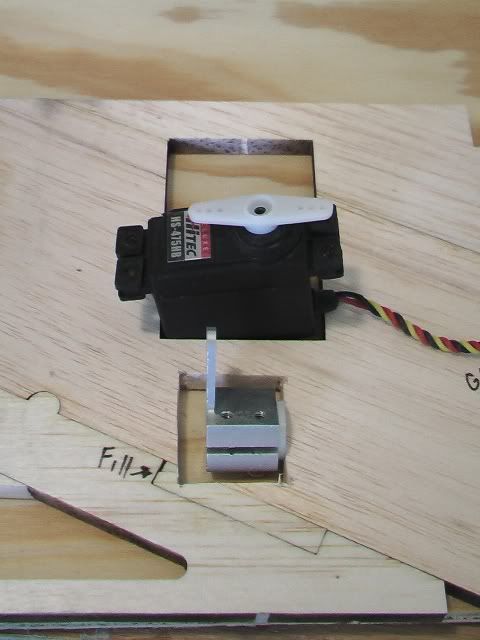
Figure 1
Next, I cut the 9/32 brass tube in three sections to accommodate the control horns and cut a space in the stab (along the 3 lines I drew earlier) to embed the sections within it (Figure 2). Took quite a bit of deburring to have the control rod rotate freely. I found that a sharp exacto knife is perfect for this task. Also, I constantly checked that the cuts where 90 degrees from the vertical.
Note:
I changed the control rod to steel because it is stronger than Aluminum and has a better freedom of motion in the glide tube.
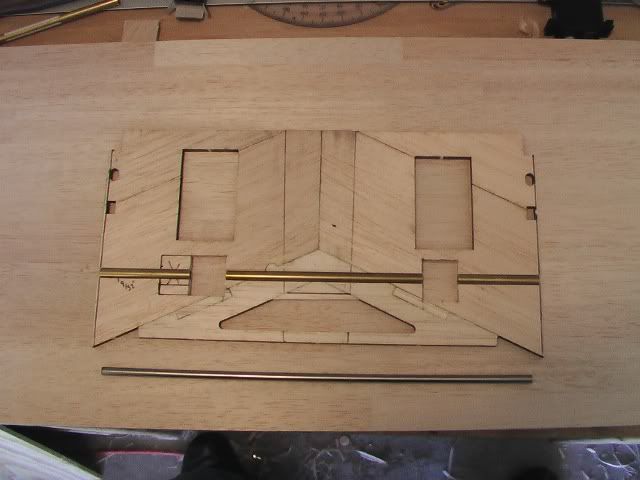
Figure 2
Since the stabilator will only move 3/4"-1" I did not want or need the servo to be far from the control horn so I positioned it 1.5" from the servo arm (Figure 1). This coupled with 1/8" push rods (for the stabilator) will reduce the chance of flutter.
Figure 1
Next, I cut the 9/32 brass tube in three sections to accommodate the control horns and cut a space in the stab (along the 3 lines I drew earlier) to embed the sections within it (Figure 2). Took quite a bit of deburring to have the control rod rotate freely. I found that a sharp exacto knife is perfect for this task. Also, I constantly checked that the cuts where 90 degrees from the vertical.
Note:
I changed the control rod to steel because it is stronger than Aluminum and has a better freedom of motion in the glide tube.
Figure 2
05-13-2006 | 11:48 PM
#28
Thread Starter
Senior Member
My Feedback: (1)
Joined: Jun 2005
Posts: 825
Likes: 0
Received 0 Likes
on
0 Posts
From: Antelope Valley,
CA
RE: Highly Modified AK Models SU-27 Build Thread
First, I used a straight edge to align the top and bottom halves of the stab and tack glue the brass tube in the stab with thin CA (Figure 1). Then inserted the steel rod to align the assembly.
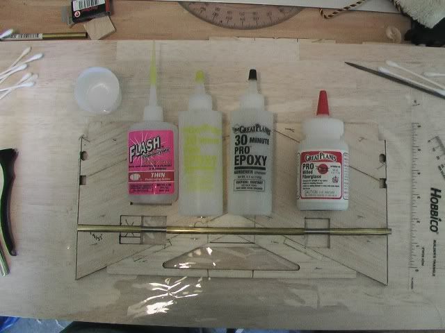
Figure 1
Second, I smeared a liberal amount of vaseline on the exposed portions of the steel rod (Figure 2).
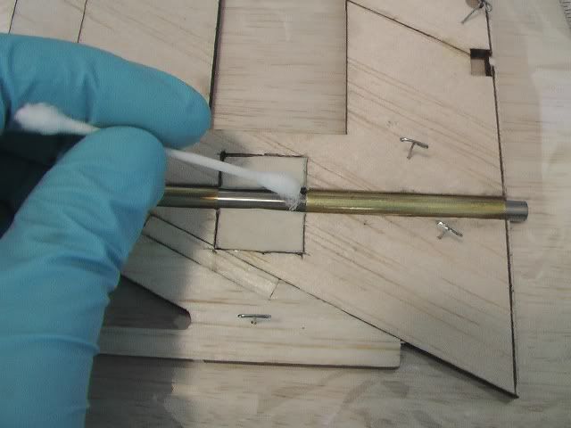
Figure 2
Third, I filled in both sides of the brass tube with a mix of 30 min epoxy and milled fiberglass (Figure 3). Then pinned the stab to a flat sure and let it dry.
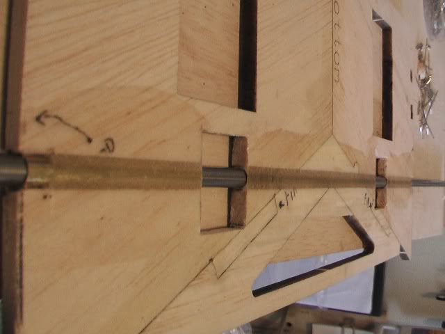
Figure 3
Figure 1
Second, I smeared a liberal amount of vaseline on the exposed portions of the steel rod (Figure 2).
Figure 2
Third, I filled in both sides of the brass tube with a mix of 30 min epoxy and milled fiberglass (Figure 3). Then pinned the stab to a flat sure and let it dry.
Figure 3
05-13-2006 | 11:59 PM
#29
Thread Starter
Senior Member
My Feedback: (1)
Joined: Jun 2005
Posts: 825
Likes: 0
Received 0 Likes
on
0 Posts
From: Antelope Valley,
CA
RE: Highly Modified AK Models SU-27 Build Thread
Stabilator/ Control Rod
After a few curse words and gnashing of teeth, I managed to bend the control rods 90 degrees (Figure 1)
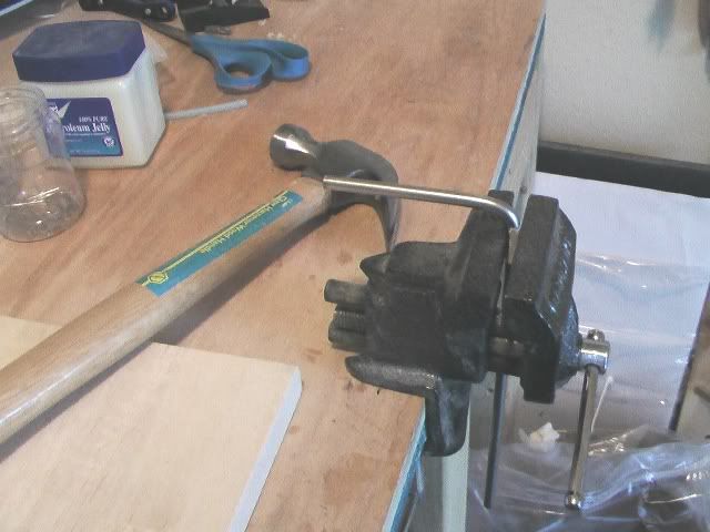
Figure 1
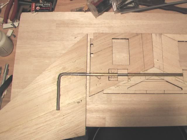
Embedded the control rod in the stabilator, filled with epoxy and used weights to keep the rod and stabilator level (Figure 2)
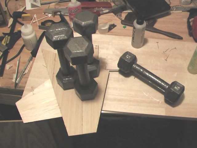
Figure 2
Semi-Finished Product
Next
Tomorrow I plan to balance and fiberglass the stabilator. Once that is completed, will install the stab in the fuse and begin reinforcing the stab & fuse.
More to Come
Mods
After a few curse words and gnashing of teeth, I managed to bend the control rods 90 degrees (Figure 1)
Figure 1
Embedded the control rod in the stabilator, filled with epoxy and used weights to keep the rod and stabilator level (Figure 2)
Figure 2
Semi-Finished Product
Next
Tomorrow I plan to balance and fiberglass the stabilator. Once that is completed, will install the stab in the fuse and begin reinforcing the stab & fuse.
More to Come
Mods
05-14-2006 | 08:28 AM
#30

Joined: Mar 2002
Posts: 796
Likes: 0
Received 0 Likes
on
0 Posts
From: Galesburg, IL
RE: Highly Modified AK Models SU-27 Build Thread
I understand what you are doing here but I have one question for you. Unless you plan on mixing the elevators with the ailerons why not make the elevator control rod connect bothe the elevators and use only one servo insteat of two servos. Would help on a positive control of the elevator and help reduce weight and one less servo to calibrate and sink with the other. Just a thought. Mines done and am waiting for my engine and I'll be ready to burn up the sky . But I do like what you are doing though.
. But I do like what you are doing though.
05-14-2006 | 09:47 AM
#31

Senior Member
Joined: Jan 2005
Posts: 852
Likes: 0
Received 0 Likes
on
0 Posts
From: Sydney, AUSTRALIA
RE: Highly Modified AK Models SU-27 Build Thread
I like this set up..looks like a winner..I prefer this system over the torque rods used in the manual....mine still sits in the box I might actually get around to building it , if I dont end up having to sell it!!!
MRM..I like your work!
cheers
MRM..I like your work!
cheers
05-14-2006 | 10:53 AM
#32
Thread Starter
Senior Member
My Feedback: (1)
Joined: Jun 2005
Posts: 825
Likes: 0
Received 0 Likes
on
0 Posts
From: Antelope Valley,
CA
RE: Highly Modified AK Models SU-27 Build Thread
ORIGINAL: nchrome
Unless you plan on mixing the elevators with the ailerons
Unless you plan on mixing the elevators with the ailerons
. I refer to the control surfaces as stabilators, but in actuality they are ailerators (function both as ailerons and elevators). As to the weight factor, I'm hoping the hardware from the other mods in the forward section of the aircraft (speed brake, L.E. Flaps) will help balance out the tail without adding a ton of weight in the nose. I do know that I'll have to move the radio equipment as far forward as possible for CG.
ORIGINAL: Haveblue
MRM..I like your work!
MRM..I like your work!
Thanks for the kind words
Mods
05-14-2006 | 11:24 AM
#33

My Feedback: (6)
Joined: Aug 2002
Posts: 690
Likes: 0
Received 0 Likes
on
0 Posts
From: Columbia, MD
RE: Highly Modified AK Models SU-27 Build Thread
Wow, this is really intrigging. I could not help from jumping in with a question about mixing the of the stabilizers to make them function as ailerators. What are your plans for the aileron-to-stabilizer mix? That could get pretty bizar ! !
05-14-2006 | 12:19 PM
#34
My Feedback: (18)
Joined: Nov 2004
Posts: 115
Likes: 0
Received 0 Likes
on
0 Posts
From: Clarkston, MI
RE: Highly Modified AK Models SU-27 Build Thread
Mods- You are the MAN! Every day I get home from work, the first thing that happens is the computer is fired off just to see the next 'MODS' episode. This is a great thread. Better than a good book. ...and your 'screen shots'...TO DIE FOR. ahemm..very helpful. I was wondering what you picked for a power plant. When I get around to building mine, I plan to pump the fuel with a VP-30 so I can put the tank over the CG. That will take some weight out of the fore so less to worry about the aft. I am an aft-man. Less junk-in-the-trunk makes for a great aft.
steelie
ahemm..very helpful. I was wondering what you picked for a power plant. When I get around to building mine, I plan to pump the fuel with a VP-30 so I can put the tank over the CG. That will take some weight out of the fore so less to worry about the aft. I am an aft-man. Less junk-in-the-trunk makes for a great aft.steelie
05-14-2006 | 08:51 PM
#35
 RE: Highly Modified AK Models SU-27 Build Thread
Looking very, very good!
One thing I would reconsider is the stab balancing. I am not sure that is even needed, as every jet I ever saw with the radio turned off, the stabs were hanging down, and they fly just fine without being balanced. As a matter of fact, they actually "weather vane" when the plane is in flight, so the load on the servos is decreased. The debate on the pros and cons of stab balancing is always going on in the Jets forum. But, each to his own. I would balance them slightly rear heavy myself.
Spar
BTW, this is the best bottom shot of the jet. Not the best, but, you should be able to use it for the scheme.
One thing I would reconsider is the stab balancing. I am not sure that is even needed, as every jet I ever saw with the radio turned off, the stabs were hanging down, and they fly just fine without being balanced. As a matter of fact, they actually "weather vane" when the plane is in flight, so the load on the servos is decreased. The debate on the pros and cons of stab balancing is always going on in the Jets forum. But, each to his own. I would balance them slightly rear heavy myself.
Spar
BTW, this is the best bottom shot of the jet. Not the best, but, you should be able to use it for the scheme.
05-14-2006 | 11:33 PM
#36
Thread Starter
Senior Member
My Feedback: (1)
Joined: Jun 2005
Posts: 825
Likes: 0
Received 0 Likes
on
0 Posts
From: Antelope Valley,
CA
RE: Highly Modified AK Models SU-27 Build Thread
I could not help from jumping in with a question about mixing the of the stabilizers to make them function as ailerators. What are your plans for the aileron-to-stabilizer mix?
TO DIE FOR
As a matter of fact, they actually "weather vane" when the plane is in flight, so the load on the servos is decreased. The debate on the pros and cons of stab balancing is always going on in the Jets forum. But, each to his own. I would balance them slightly rear heavy myself.
Mods
05-14-2006 | 11:47 PM
#37
Thread Starter
Senior Member
My Feedback: (1)
Joined: Jun 2005
Posts: 825
Likes: 0
Received 0 Likes
on
0 Posts
From: Antelope Valley,
CA
RE: Highly Modified AK Models SU-27 Build Thread
Didn't accomplish all that I planned, but today was productive. The "honey do" list just kept getting longer and longer.
Ailerator Mod Cont
Performed a quick balance using the stick on weights from tower hobbies. Per the suggestion above, the stab is slightly tail heavy. Since I'm embedding the weights in the stab, I cut off the adhesive tape (Figure 1).
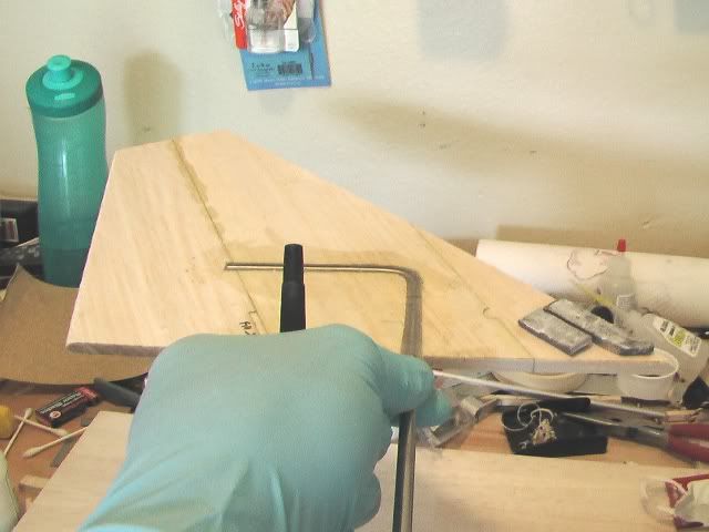
Figure 1
Next, made a poor mans depth gage by wrapping tape around the blade about the same thickness as the weights Figure 2).
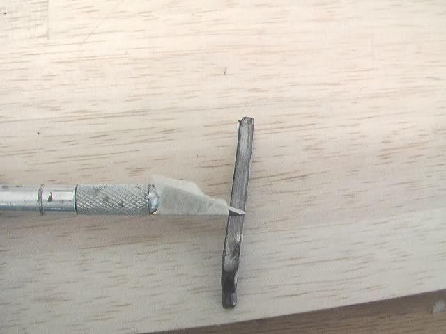
Figure 2
Then, outlined the area to be hollowed out with a felt tip pen and cut around it with the depth gage from previous step. Lastly, hollowed out the opening with a micro screwdriver (Figure 3).
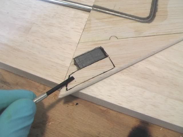
Figure 3
Ailerator Mod Cont
Performed a quick balance using the stick on weights from tower hobbies. Per the suggestion above, the stab is slightly tail heavy. Since I'm embedding the weights in the stab, I cut off the adhesive tape (Figure 1).
Figure 1
Next, made a poor mans depth gage by wrapping tape around the blade about the same thickness as the weights Figure 2).
Figure 2
Then, outlined the area to be hollowed out with a felt tip pen and cut around it with the depth gage from previous step. Lastly, hollowed out the opening with a micro screwdriver (Figure 3).
Figure 3
05-14-2006 | 11:53 PM
#38
Thread Starter
Senior Member
My Feedback: (1)
Joined: Jun 2005
Posts: 825
Likes: 0
Received 0 Likes
on
0 Posts
From: Antelope Valley,
CA
RE: Highly Modified AK Models SU-27 Build Thread
With the materials shown below I secured the lead weights in the stab using the same technique to embed the control rod (Figures 1-3).
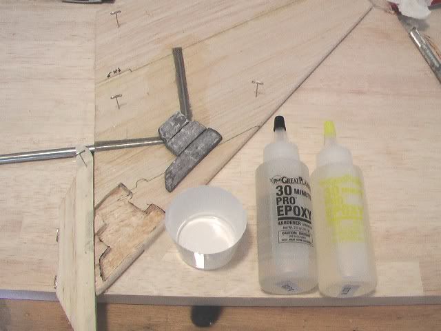
Figure 1
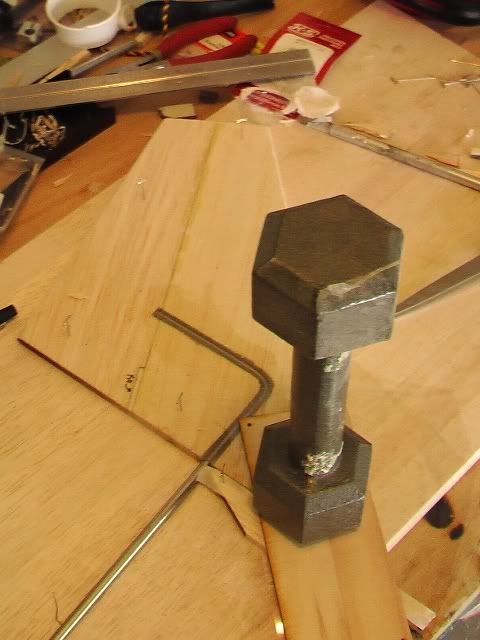
Figure 2
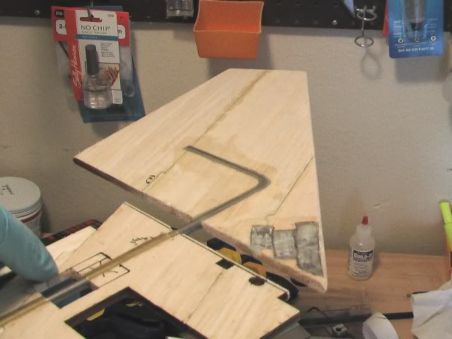
Figure 3
Figure 1
Figure 2
Figure 3
05-15-2006 | 12:06 AM
#39
Thread Starter
Senior Member
My Feedback: (1)
Joined: Jun 2005
Posts: 825
Likes: 0
Received 0 Likes
on
0 Posts
From: Antelope Valley,
CA
RE: Highly Modified AK Models SU-27 Build Thread
All hardware installed (Figure 1)
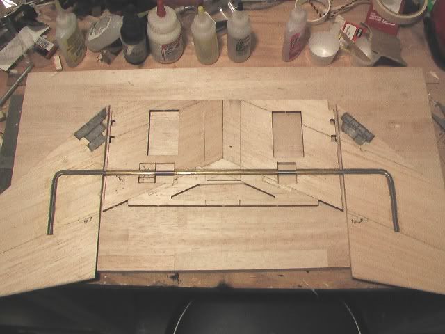
Figure 1
Fiberglassing
My past fiberglass jobs were not all that great so I did some digging on ways to even out the epoxy so I won't have to sand so much after it cures. Got a really good tip about using platic food wrap after squeegeeing out all of the epoxy.
Materials used (Figures 2 & 3).
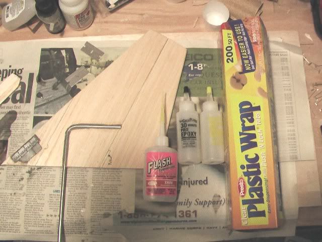
Figure 2
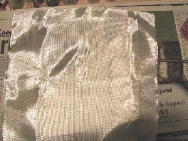
Figure 3
The plastic wrap worked great. It's pretty even now before sanding (Figure 2). One side down 3 to go.
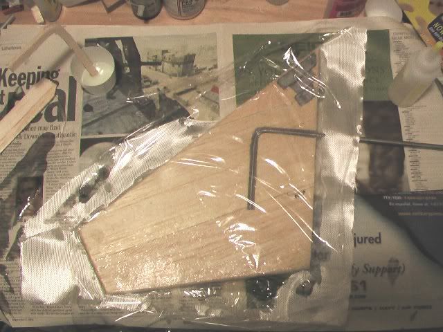
Figure 4
Next
Finish fiberglassing the ailerators and install in fuse. Thanks for your suggestions everyone. Keep em coming.
More to come,
Mods
Figure 1
Fiberglassing
My past fiberglass jobs were not all that great so I did some digging on ways to even out the epoxy so I won't have to sand so much after it cures. Got a really good tip about using platic food wrap after squeegeeing out all of the epoxy.
Materials used (Figures 2 & 3).
Figure 2
Figure 3
The plastic wrap worked great. It's pretty even now before sanding (Figure 2). One side down 3 to go.
Figure 4
Next
Finish fiberglassing the ailerators and install in fuse. Thanks for your suggestions everyone. Keep em coming.
More to come,
Mods
05-16-2006 | 07:38 AM
#41
Senior Member
My Feedback: (32)
Joined: Sep 2004
Posts: 230
Likes: 0
Received 0 Likes
on
0 Posts
From: Maryville,
TN
RE: Highly Modified AK Models SU-27 Build Thread
Looking good, and very creative. I may take a shot at building one after I see how yours turns out.[sm=thumbup.gif]
05-16-2006 | 09:05 AM
#42

Joined: Mar 2004
Posts: 725
Likes: 0
Received 0 Likes
on
0 Posts
From: Cedar Park, TX
RE: Highly Modified AK Models SU-27 Build Thread
ORIGINAL: phantom driver
Looking good, and very creative. I may take a shot at building one after I see how yours turns out.[sm=thumbup.gif]
Looking good, and very creative. I may take a shot at building one after I see how yours turns out.[sm=thumbup.gif]
Mods-R-Me. Very interesting build thread. I've followed your Super Skybolt thread and once again you're doing excellent work. Keep it up. [sm=thumbup.gif] Do you know what kind of speed this plane will fly at? I'm afraid it will be too fast for me right now, but I'll still be interested in building it.
-tychoc
05-16-2006 | 02:30 PM
#43
Thread Starter
Senior Member
My Feedback: (1)
Joined: Jun 2005
Posts: 825
Likes: 0
Received 0 Likes
on
0 Posts
From: Antelope Valley,
CA
RE: Highly Modified AK Models SU-27 Build Thread
ORIGINAL: tychoc
Same here. This looks like an interesting kit and the price is right.
Mods-R-Me. Very interesting build thread. I've followed your Super Skybolt thread and once again you're doing excellent work. Keep it up. [sm=thumbup.gif] Do you know what kind of speed this plane will fly at? I'm afraid it will be too fast for me right now, but I'll still be interested in building it.
-tychoc
ORIGINAL: phantom driver
Looking good, and very creative. I may take a shot at building one after I see how yours turns out.[sm=thumbup.gif]
Looking good, and very creative. I may take a shot at building one after I see how yours turns out.[sm=thumbup.gif]
Mods-R-Me. Very interesting build thread. I've followed your Super Skybolt thread and once again you're doing excellent work. Keep it up. [sm=thumbup.gif] Do you know what kind of speed this plane will fly at? I'm afraid it will be too fast for me right now, but I'll still be interested in building it.
-tychoc
My SU-27 will be powered by a Jett 90L. Based on the other AKM SU-27 build thread it should go at least 100mph straight & level. I've been busy the last two days and will try to post more pics in the mean time.
Mods
05-16-2006 | 05:44 PM
#44
Thread Starter
Senior Member
My Feedback: (1)
Joined: Jun 2005
Posts: 825
Likes: 0
Received 0 Likes
on
0 Posts
From: Antelope Valley,
CA
RE: Highly Modified AK Models SU-27 Build Thread
ORIGINAL: iFLYrc_Vic
Wow, this is really intrigging. I could not help from jumping in with a question about mixing the of the stabilizers to make them function as ailerators. What are your plans for the aileron-to-stabilizer mix? That could get pretty bizar ! !
Wow, this is really intrigging. I could not help from jumping in with a question about mixing the of the stabilizers to make them function as ailerators. What are your plans for the aileron-to-stabilizer mix? That could get pretty bizar ! !
Sorry it took so long to give you and answer. Rather than give a lengthly explanation, I found this video of an actual SU-27 in preflight. It shows all the surfaces mixing together; my plane will resemble this very closely.
Check it Out: [link=http://s60.photobucket.com/albums/h32/Mods-R-Me/?action=view¤t=SU-27Preflight.flv]CLICK HERE[/link]
Mods
05-21-2006 | 09:50 PM
#45
Thread Starter
Senior Member
My Feedback: (1)
Joined: Jun 2005
Posts: 825
Likes: 0
Received 0 Likes
on
0 Posts
From: Antelope Valley,
CA
RE: Highly Modified AK Models SU-27 Build Thread
Phase 2 of Full Flying Stab Mod Complete
Summary
AKs' stab design is really impressive. Only problem is its made entirely out of balsa so I chose not to change the design but just reinforce it at critical locations. The mod is 95% complete. It took 5 days to design and 2 days to install/fabricate the parts. The mod added 14 oz to the aft end [&:]. This is due to the two steel control rods weighing 4-5 oz each. The aluminum weighs less that half that. This is my first time attempting this type of mod so I will error on the side of caution. Steel is much stronger than aluminum so if flight testing shows that I don't need that much strength, I'll switch over. By all means I wish to avoid adding a ton of "dead" weight (a mass that serves no purpose other than to add ballast for CG) to the nose so I'm relocating certain components forward to compensate (Figure 1). I've ran into this situation before and this solution got me out of trouble every time. I might have to add SOME dead weight but a few grams is much better than several ounces.
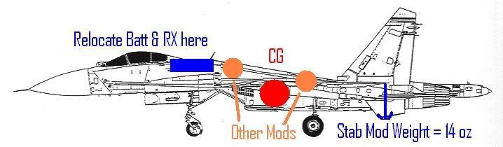
Figure 1
I just purchased this rip saw attachment for cutting plywood (Figure 2). I glides through wood up to 1/4 inch with ease and only costs $29.95 at Lowes. I don't know how I cut ply before without it [sm=confused.gif]. YOU GOT TO GET ONE [sm=thumbup.gif].
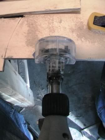
Figure 2
Stab Strengthening
Taking a page from AK's playbook, I cut and glued doublers for formers F8 & F9 out of 1/16" ply (Figure 2) using thick CA. This increases the lateral strength of the formers without adding a lot of weight.
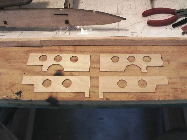
Figure 3
Summary
AKs' stab design is really impressive. Only problem is its made entirely out of balsa so I chose not to change the design but just reinforce it at critical locations. The mod is 95% complete. It took 5 days to design and 2 days to install/fabricate the parts. The mod added 14 oz to the aft end [&:]. This is due to the two steel control rods weighing 4-5 oz each. The aluminum weighs less that half that. This is my first time attempting this type of mod so I will error on the side of caution. Steel is much stronger than aluminum so if flight testing shows that I don't need that much strength, I'll switch over. By all means I wish to avoid adding a ton of "dead" weight (a mass that serves no purpose other than to add ballast for CG) to the nose so I'm relocating certain components forward to compensate (Figure 1). I've ran into this situation before and this solution got me out of trouble every time
. I might have to add SOME dead weight but a few grams is much better than several ounces. Figure 1
I just purchased this rip saw attachment for cutting plywood (Figure 2). I glides through wood up to 1/4 inch with ease and only costs $29.95 at Lowes. I don't know how I cut ply before without it [sm=confused.gif]. YOU GOT TO GET ONE [sm=thumbup.gif].
Figure 2
Stab Strengthening
Taking a page from AK's playbook, I cut and glued doublers for formers F8 & F9 out of 1/16" ply (Figure 2) using thick CA. This increases the lateral strength of the formers without adding a lot of weight.
Figure 3
05-21-2006 | 10:11 PM
#46
Thread Starter
Senior Member
My Feedback: (1)
Joined: Jun 2005
Posts: 825
Likes: 0
Received 0 Likes
on
0 Posts
From: Antelope Valley,
CA
RE: Highly Modified AK Models SU-27 Build Thread
Stab Strengthening Cont.
The stab section slides into the fuse and is glued to the back of former F8. I figured the majority of the control rod stress would be concentrated here so I cut 1/4 inch ply doublers, then glued them to each side of the fuse with 30 min epoxy & milled fiberglass (30E+MF)
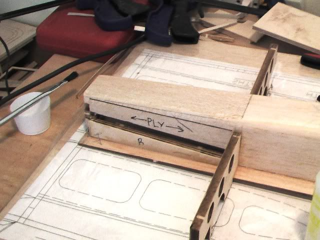
Figure 1
Next, I slid the stab into place and checked that it was aligned with the fuse by sticking a T pin on the center of the nose and measured the distance with a tape measure (figure 2). Then, tack glued it to the back of former F8 with thin CA (figure 3).
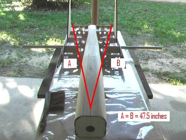
Figure 2
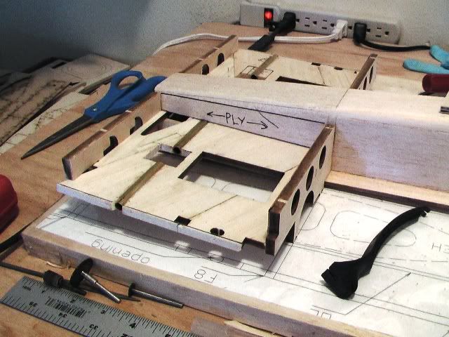
Figure 3
The stab section slides into the fuse and is glued to the back of former F8. I figured the majority of the control rod stress would be concentrated here so I cut 1/4 inch ply doublers, then glued them to each side of the fuse with 30 min epoxy & milled fiberglass (30E+MF)
Figure 1
Next, I slid the stab into place and checked that it was aligned with the fuse by sticking a T pin on the center of the nose and measured the distance with a tape measure (figure 2). Then, tack glued it to the back of former F8 with thin CA (figure 3).
Figure 2
Figure 3
05-21-2006 | 10:27 PM
#47
Thread Starter
Senior Member
My Feedback: (1)
Joined: Jun 2005
Posts: 825
Likes: 0
Received 0 Likes
on
0 Posts
From: Antelope Valley,
CA
RE: Highly Modified AK Models SU-27 Build Thread
Stab Strengthening Cont.
Added the top portion of the 1/4 inch ply fuse doubler to each side (Figure 1)

Figure 1
Next, strengthened the servo/control horn area on the stab with 1/8 inch ply panels. The glide tube rises 1/32" above the stab so I had to cut a grove into them so they can lye flat. I then glued it in place with thick CA chased by thin CA on the edges. This space has a large area held together by a relatively thin strip of balsa so the ply is really needed here (figures 2 & 3).
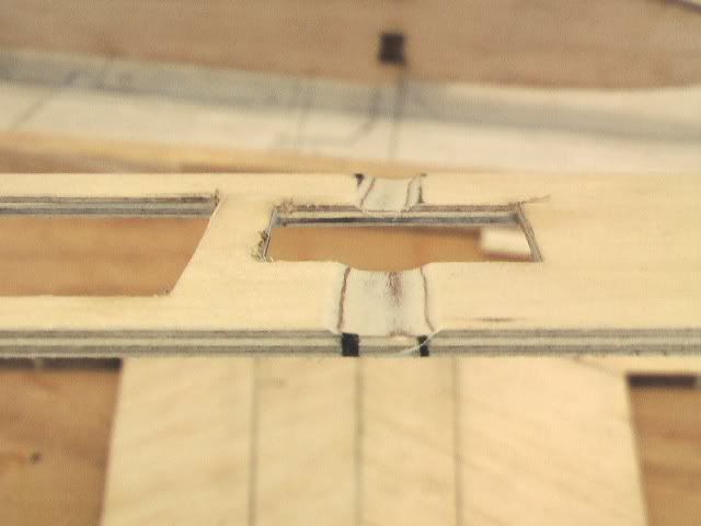
Figure 2
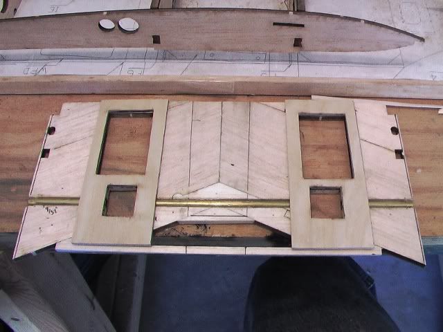
Figure 3
Added the top portion of the 1/4 inch ply fuse doubler to each side (Figure 1)
Figure 1
Next, strengthened the servo/control horn area on the stab with 1/8 inch ply panels. The glide tube rises 1/32" above the stab so I had to cut a grove into them so they can lye flat. I then glued it in place with thick CA chased by thin CA on the edges. This space has a large area held together by a relatively thin strip of balsa so the ply is really needed here (figures 2 & 3).
Figure 2
Figure 3
05-21-2006 | 10:47 PM
#48
Thread Starter
Senior Member
My Feedback: (1)
Joined: Jun 2005
Posts: 825
Likes: 0
Received 0 Likes
on
0 Posts
From: Antelope Valley,
CA
RE: Highly Modified AK Models SU-27 Build Thread
Stab Strengthening Cont.
Installed former(s) F9 to back of stab (figure 1) and glued with thick CA.
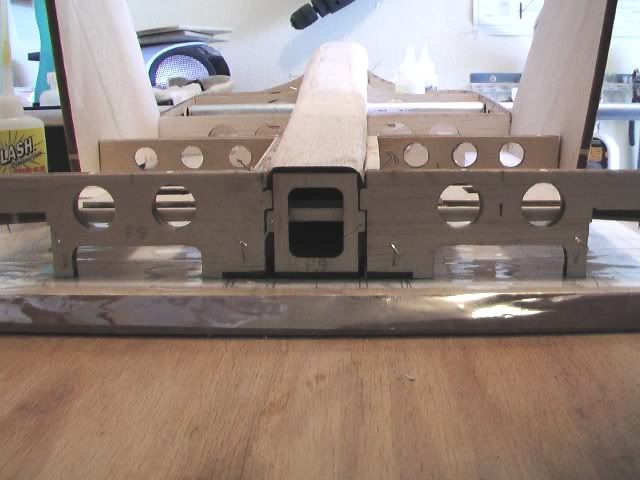
Figure 1
The next high stress area is right where the ailerator connects to the stab. I used 1/4 inch ply cut to the same dimensions as the fuse doubler (figure 2). This ply serves three purposes: 1. gives additional surface area to adhere the fin to, 2. stabilizes the glide tube, 3. reduces vibration to the ailerator.
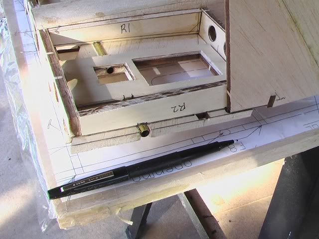
Figure 2
Installed former(s) F9 to back of stab (figure 1) and glued with thick CA.
Figure 1
The next high stress area is right where the ailerator connects to the stab. I used 1/4 inch ply cut to the same dimensions as the fuse doubler (figure 2). This ply serves three purposes: 1. gives additional surface area to adhere the fin to, 2. stabilizes the glide tube, 3. reduces vibration to the ailerator.
Figure 2
05-21-2006 | 10:57 PM
#49
Thread Starter
Senior Member
My Feedback: (1)
Joined: Jun 2005
Posts: 825
Likes: 0
Received 0 Likes
on
0 Posts
From: Antelope Valley,
CA
RE: Highly Modified AK Models SU-27 Build Thread
Stab Strengthening Cont.
Next, used a 90 square to install fin and dry fit the ply doublers right up against it (figure 1). Then, glued it in place with 30E+MF (figure 2). I promptly removed the fins before the glue cured.
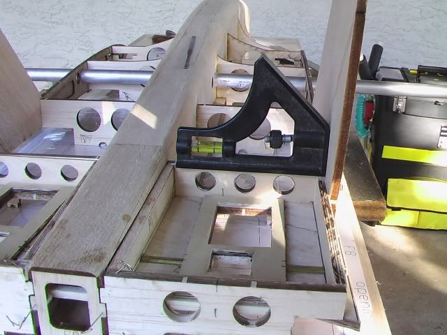
Figure 1
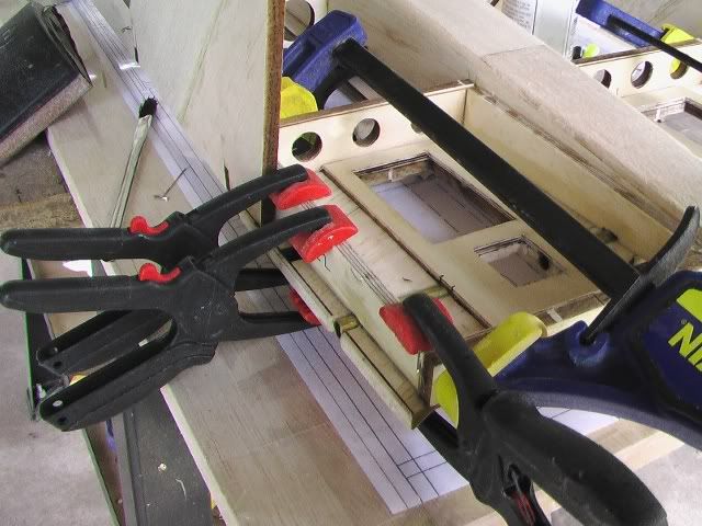
Figure 2
Semi-Finished Product
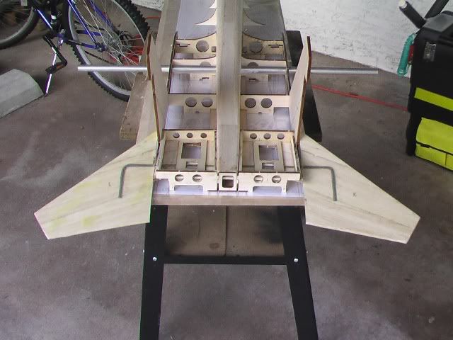
Next- Phase 3
Phase 3 will be sheeting the fuse top and encasing the ends of the glide tube with ply (just a little). I took off 2 weeks from work so I should be able to get some work done in the shop!
More to come,
Mods
Next, used a 90 square to install fin and dry fit the ply doublers right up against it (figure 1). Then, glued it in place with 30E+MF (figure 2). I promptly removed the fins before the glue cured
. Figure 1
Figure 2
Semi-Finished Product
Next- Phase 3
Phase 3 will be sheeting the fuse top and encasing the ends of the glide tube with ply (just a little). I took off 2 weeks from work so I should be able to get some work done in the shop!
More to come,
Mods
05-21-2006 | 11:59 PM
#50
Senior Member
Joined: Jan 2006
Posts: 558
Likes: 0
Received 0 Likes
on
0 Posts
From: Nettleton,
MS
RE: Highly Modified AK Models SU-27 Build Thread
mods - YOU ARE THE MAN.....i first want to say, like the skybolt, you're doing a great job on this one as well and i also want to thank you for the detailed builds. i've learned a lot by keeping up with them and i've thought of a couple mods for my next project (to be determined).

