


Tillotson carb question..!!
 03-14-2026 | 08:52 AM
#1

Thread Starter

Howdy all "gassers" out there.! I am currently cleaning and refurbishing a Tillotson HU134A 036 carb on a DLA 32cc engine using the repair kit RK-31-HU just bought from Tillotson on Ireland.
All seems straightforward except one thing that really puzzles me:
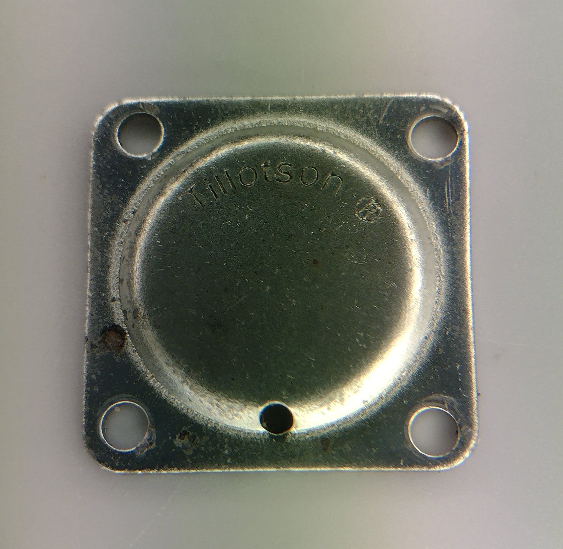
In the kit is included a new circular aluminium cup which appears to have its "old friend" situated under the pump membrane. It is evident that the old cup has been punched into place since it has become somewhat "flattened" in the process. See attached pic.
My question to you all: How can I remove the old cup since it is impossible to push it out from behind..?!?!?! Should I remove it at all, or just leave the old cup as is and only change filter, gaskets and membranes..?? Why then is the cup included in the kit..?? Have searched this site for info on this but not found what I seek and therefore I will be very grateful for all input I can get from you. Thanks in advance/canardlover

All seems straightforward except one thing that really puzzles me:
In the kit is included a new circular aluminium cup which appears to have its "old friend" situated under the pump membrane. It is evident that the old cup has been punched into place since it has become somewhat "flattened" in the process. See attached pic.
My question to you all: How can I remove the old cup since it is impossible to push it out from behind..?!?!?! Should I remove it at all, or just leave the old cup as is and only change filter, gaskets and membranes..?? Why then is the cup included in the kit..?? Have searched this site for info on this but not found what I seek and therefore I will be very grateful for all input I can get from you. Thanks in advance/canardlover
 03-14-2026 | 06:41 PM
#2
Howdy all "gassers" out there.! I am currently cleaning and refurbishing a Tillotson HU134A 036 carb on a DLA 32cc engine using the repair kit RK-31-HU just bought from Tillotson on Ireland.
All seems straightforward except one thing that really puzzles me:
In the kit is included a new circular aluminium cup which appears to have its "old friend" situated under the pump membrane. It is evident that the old cup has been punched into place since it has become somewhat "flattened" in the process. See attached pic.
My question to you all: How can I remove the old cup since it is impossible to push it out from behind..?!?!?! Should I remove it at all, or just leave the old cup as is and only change filter, gaskets and membranes..?? Why then is the cup included in the kit..?? Have searched this site for info on this but not found what I seek and therefore I will be very grateful for all input I can get from you. Thanks in advance/canardlover
That fuel channel CAN collect dirt, and the only way to properly clean it is to pull the plug, but these plugs are one-time-use only. Hence the new plug.
If you have the tools and skills, I would pull, clean and re-plug. If not, I would not worry too much about it, just keep it in mind as a last resort if the replacement of membranes does not lead to the desired results.
The usually best way to pull these plugs is to very carefully drill a small hole in it (taking GREAT care that the drill does NOT "shoot" through and touch anything behind the plug) and carefully pry it out with a small bent hook in a piece of wire or something like that. Best is to drill slightly off centre.
Pay attention to not scratch the bore in which the plug is sitting, or the new plug could possibly leak.
That is the method Tillotson generally recommends, although I have the impression that most of the info out there is about the larger SkiDoo carbs.
Principle remains the same though.
But as said, most likely there is not much to clean there, I would first blow it out with compressed air and carb cleaner or such. Most cases, that should do it.
 03-15-2026 | 07:56 AM
#3
Thread Starter
Thanks a lot brutus for your quick, informative and "balanced" reply..!!!! Since the engine ran well enough even before my � �just in case� - dismantling of the carb and since I found very little dirt inside I will allow the old cup to fly a few more times. The metal screen filter had very little debris in it.
Now, please let me "pick your brain(s)" on one more item regarding this carb: Previously the engine has been running with cylinder pointing upwards but my Bucker Jungmann 1/4 scale requires me to invert the engine not to destroy its scale looks. My understanding is that the small hole in the quadratic pump cover(see attachment) should always be placed with the open hole pointing downwards in order to drain any excess fuel �outside� of the membrane so I must turn the cover accordingly..?!?!
Please correct me if I�m wrong here. My manual says nothing about this.
03-15-2026 | 08:20 AM
#4
Thanks a lot brutus for your quick, informative and "balanced" reply..!!!! Since the engine ran well enough even before my � �just in case� - dismantling of the carb and since I found very little dirt inside I will allow the old cup to fly a few more times. The metal screen filter had very little debris in it.
Now, please let me "pick your brain(s)" on one more item regarding this carb: Previously the engine has been running with cylinder pointing upwards but my Bucker Jungmann 1/4 scale requires me to invert the engine not to destroy its scale looks. My understanding is that the small hole in the quadratic pump cover(see attachment) should always be placed with the open hole pointing downwards in order to drain any excess fuel �outside� of the membrane so I must turn the cover accordingly..?!?!
Please correct me if I�m wrong here. My manual says nothing about this.
Now, please let me "pick your brain(s)" on one more item regarding this carb: Previously the engine has been running with cylinder pointing upwards but my Bucker Jungmann 1/4 scale requires me to invert the engine not to destroy its scale looks. My understanding is that the small hole in the quadratic pump cover(see attachment) should always be placed with the open hole pointing downwards in order to drain any excess fuel �outside� of the membrane so I must turn the cover accordingly..?!?!
Please correct me if I�m wrong here. My manual says nothing about this.
Having said that, there are other ways possible for moisture to collect behind that cover, like rain, condensation or perhaps fuel spillage. All three far fetched, but having the hole face down probably won't hurt, just in case.
However:
That hole serves as "atmospheric sensing hole" and in rare cases, flightwind affects the pressure regulator, if for example the propwash or such blows straight into that hole.
Some people therefore solder a short piece of tubing on the hole, and slip on a piece of fuel tubing that leads to a "quieter place", for example in the fuselage behind the firewall.
It is rarely necessary, but I have seen it once or twice that the engine ran perfect on the ground, but became unpredictable and erratic in the air, with no needle setting that would cure it. In those rare cases the additional fuel tubing, quieting down the wind roar in the sensing hole would solve the issue.
Since you are relocating the engine to another plane, the possibility arises that this engine, once running great in its previous situation, could act up as these things are unpredictable. Rare, but unpredictable.
 03-15-2026 | 01:23 PM
#6
Thread Starter
Now the carb is assembled and mounted to the engine. As you see it is not about up or down - sorry my fault - but rather forward/rearward or sidewise for the sensing hole. I guess no-one can say for sure which way is to be preferred.. so I will let it point rearwards for the time being
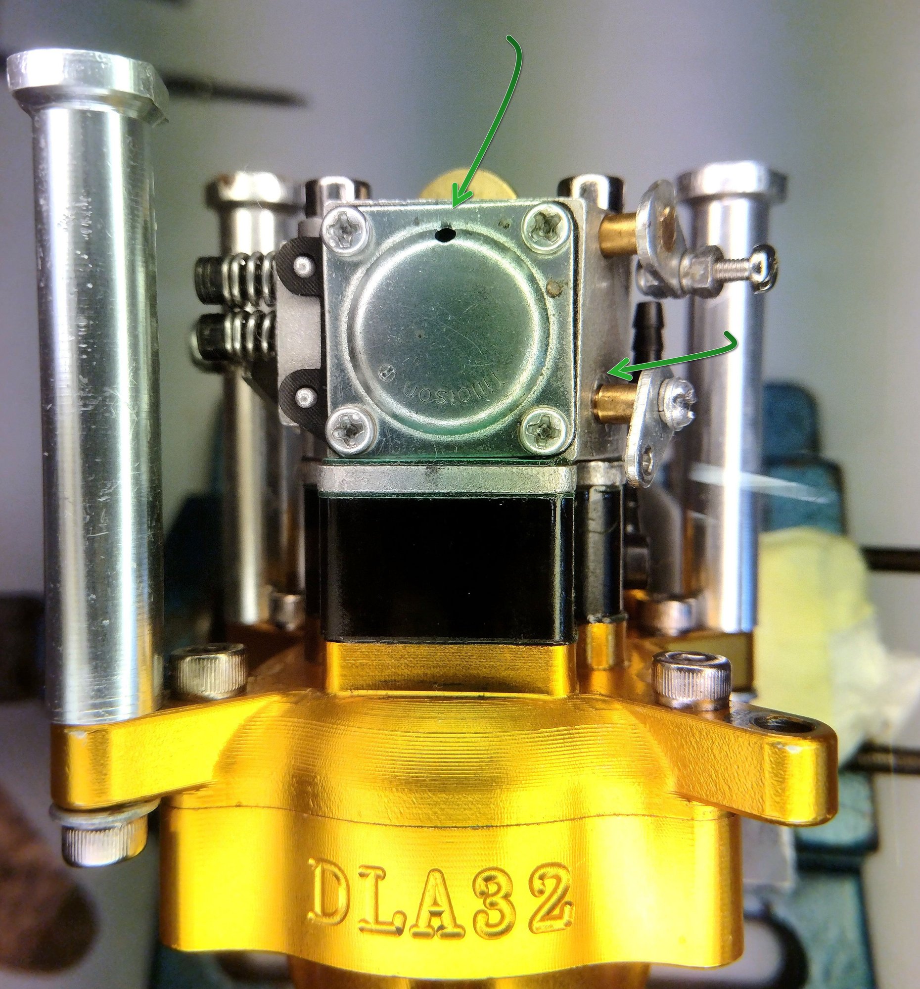

. Viewpoints please..!!
so I will let it point rearwards for the time being. Viewpoints please..!!
03-15-2026 | 09:15 PM
#7
That location should not be any issue. Being unfamiliar with the engine I assumed (yes, I know, I shouldn't have done that, it's got the word "ass" in it) that the carb would be mounted on the cylinder, sideways (port-induction), like many of the Zenoah's, which would much more expose the carb to high velocity airflow.
I do not expect any issues there.
I do not expect any issues there.
03-16-2026 | 08:34 AM
#8
Thread Starter
Thanks again brutus.! If you look at the second green arrow to the lower right you will notice that the C-clip is missing from the throttle axle. This is intentional since the throttle axle will not move freely and will not close butterfly completely with this clip in place. The reason is that the return spring pulls the axle axially, forcing the C-clip to rub hard against the throttle body... .! My intention is to have the butterfly pulled by the servo from fully closed to "full bore" and NOT utilise the idle speed adjustment screw on the carb. This enables me to shut down the engine with the throttle if need be. Does that make sense to you..?
"Save the glow engine - they make such marvellous gassers" ..!!! I like that brutus, myself having close to 100 glow engines amassed over many decades - just waiting to be converted to gas..
.! My intention is to have the butterfly pulled by the servo from fully closed to "full bore" and NOT utilise the idle speed adjustment screw on the carb. This enables me to shut down the engine with the throttle if need be. Does that make sense to you..?"Save the glow engine - they make such marvellous gassers" ..!!! I like that brutus, myself having close to 100 glow engines amassed over many decades - just waiting to be converted to gas..
Last edited by canardlover; 03-16-2026 at 08:38 AM.
03-16-2026 | 07:34 PM
#9
Thanks again brutus.! If you look at the second green arrow to the lower right you will notice that the C-clip is missing from the throttle axle. This is intentional since the throttle axle will not move freely and will not close butterfly completely with this clip in place. The reason is that the return spring pulls the axle axially, forcing the C-clip to rub hard against the throttle body....! My intention is to have the butterfly pulled by the servo from fully closed to "full bore" and NOT utilise the idle speed adjustment screw on the carb. This enables me to shut down the engine with the throttle if need be. Does that make sense to you..?
.! My intention is to have the butterfly pulled by the servo from fully closed to "full bore" and NOT utilise the idle speed adjustment screw on the carb. This enables me to shut down the engine with the throttle if need be. Does that make sense to you..?For RC use, you can omit the spring, and IF that allows reinstalling the circlip, I would do so: Any additional clearance and vibration will cause wear at the bore eventually. Better to minimize that.
As for shutting down the engine by means of the throttle, I would not rely on that. Butterfly carbs, unlike barrel-valve carbs, do not necessarily seal off the intake (they can, they should but it is not inherently guaranteed by the butterfly design) so chances are over time, this method of stopping becomes less and less reliable.
I exclusively fly "ex-glow" and haven't burned a drop of glowfuel in years, with the exception of benchtesting engines for friends, or helping them on the field.
My favourite and most often flown is the 5 cc ASP fourstroke, closely followed by the ASP FT160.
But all approx 10 active engines run on gas.
Not as active in the air lately...
But still running gas:
The possibilities are endless...
03-17-2026 | 05:30 AM
#10
Thread Starter
Again, many thanks brutus for good advice.! I will remove the return spring since I think it is a bit too strong thereby unnecesserily straining the throttle servo..!
You are of course correct that there is no guarantee that the engine will stop if throttle barrel is closed. Mine presently does stop but you never know??
At the same time I wish to pick your brain on my new throttle arm added to the carb. Here is why:
1) metal arms is a no-no to me
2) the arm is too short
3) the angle of the arm is not optimal for precise low speed throttle control. High speed control is not critical as you know.
See attached pic showing my modified Lexan extension added to rectify the above drawbacks. Viewpoints very much appreciated..!!
03-17-2026 | 05:36 AM
#11
Thread Starter
Nice boats you have there brutus..! Initially I thought you were an american but after seeing the videos and listening to your voice? it sounds like you are dutch or maybe a belgian guy..?!?
03-19-2026 | 01:41 AM
#12

About the Throttle Arm, I think that that solution will work just right, depending on the strength and gasoline resistance of the used material (cannot judge that from a picture).
03-19-2026 | 03:58 AM
#13
Thread Starter
Thanks again brutus. The returnspring is now removed and the throttle moves completely freely all the way from fully closed to fully open. I must admit that the previous problem to fully close the throttle was NOT the returnspring in itself but rather that upon closing the butterfly/axle had to move slightly sideways in order to sit correcly in the bore and come to fully closed position. And in that process it had to compress the returnspring. What I did now was to add a compression spring on the opposite side behind the throttle arm in order to hinder the valve/axle from vibrating sideways and cause excessive wear. Hope you can follow me here..??!!??
The arm extension is made of Makrolon(Lexan to the americans) and it is very tough stuff (just ask the riot policemen..) so alkylate fuel will not touch it.
The arm extension is made of Makrolon(Lexan to the americans) and it is very tough stuff (just ask the riot policemen..
) so alkylate fuel will not touch it.
The following users liked this post:
canardlover (03-20-2026)


