


Need To Know Best Way To Reinstall Cylinder on OS 61 SF Engine
 02-21-2026 | 08:05 PM
#1
Thread Starter

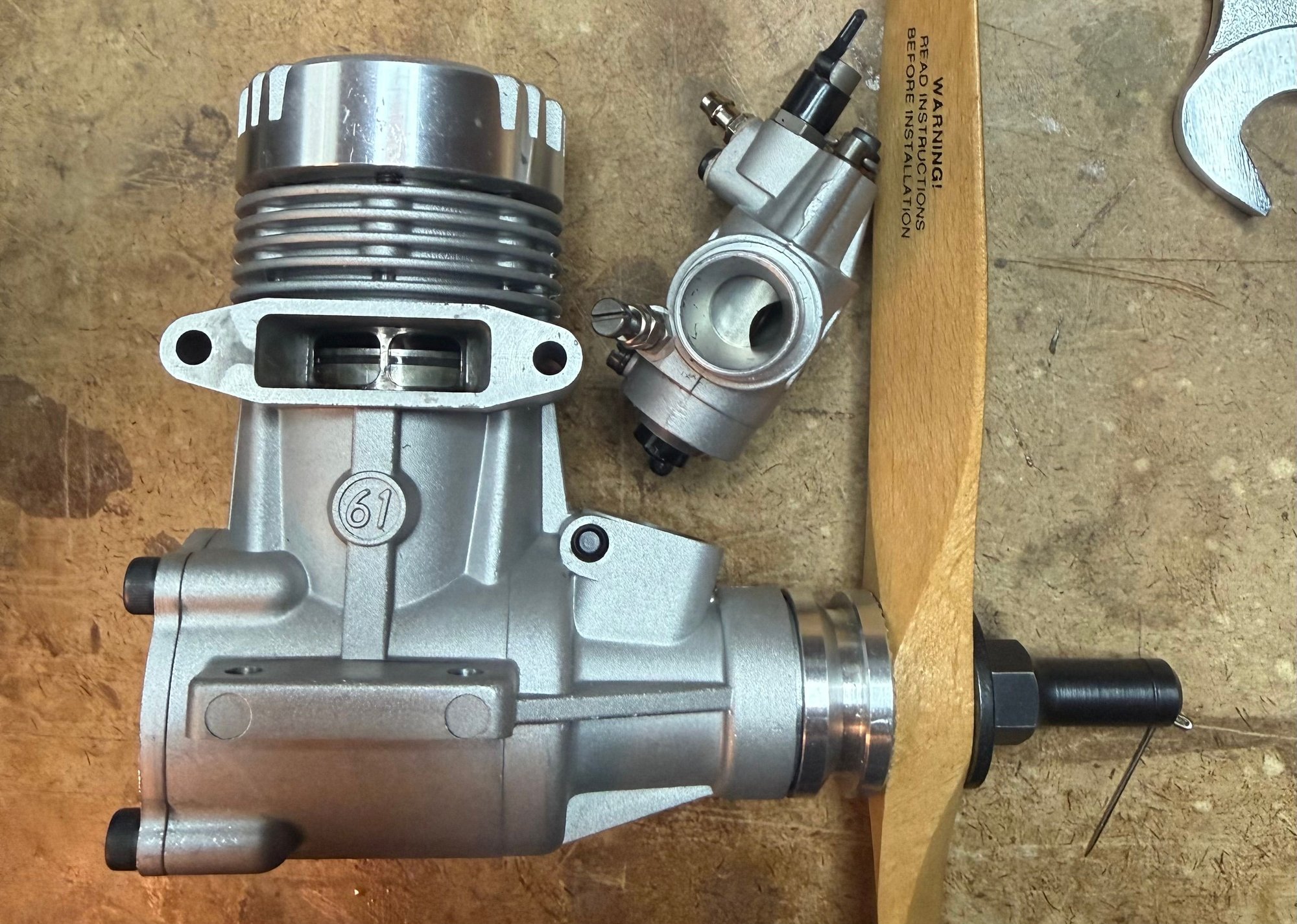
I have an OS Max 61 SF Engine that I disassembled so I could replace the bearings and the pison ring. While replacing the ring, I noticed that there is a small pin in the ring groove, and the ends of the new ring need to stay lined up on either side of that pin. However, for this engine, the connecting rod can't be installed onto the crankshaft pin with the cylinder installed. There's not enough slop in the wrist pin of the piston to allow the connecting rod to be moved rearwared enough so it can slip ofver the crank pin. So that means the cylinder needs to be installed the same way it came out, and that is with the pistion and connecting rod installed in the crankcase first. My question is what is the best way to ensure that the ring ends stay on either sid of the pin in the ring groove? When the piston ring is not in the cylinder yet, the ring ends are free to slide over that pin in the ring groove, and that's what I don't want. Let me know if there's a way to keep the ring in one place while the cylinder is installed in the top of the crankcase and slid over the top
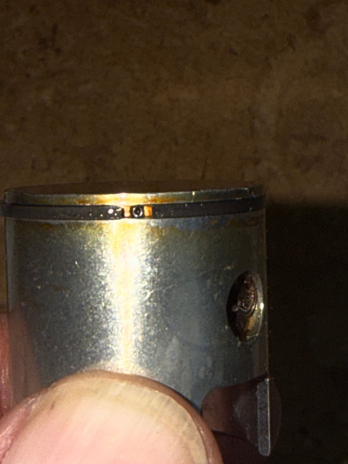
of the piston and piston ring. Thank you. From Mike D'Amico
of the piston and piston ring. Thank you. From Mike D'Amico
 02-23-2026 | 06:13 AM
#2

It is very easy!
With the piston and connecting rod installed to the crank shaft you slide/push the cylinder liner over the piston and into the crank case! Simple like that! The cylinder liner is chamfered at the bottom so all you do is push the cylinder liner over the piston ring and it will slip in with out problem!
With the piston and connecting rod installed to the crank shaft you slide/push the cylinder liner over the piston and into the crank case! Simple like that! The cylinder liner is chamfered at the bottom so all you do is push the cylinder liner over the piston ring and it will slip in with out problem!
02-23-2026 | 07:22 AM
#3
Thread Starter
My concern is ensuring that the ends of the ring stay positioned to each side of the pin in the ring groove. Getting the end of the connecting rod onto the crank pin requries a lot of fiddling around with the connecting rod and the piston, so in that process, how do you make sure the ring stays put where you place it? I'll give it a try. Maybe I can see the ends of the ring from the top of the cylinder. I marked the top of the piston with a sharpie marker so I'll know where the pin is in the ring groove.
02-23-2026 | 06:49 PM
#5
Thread Starter
Thank you for your help Jaka54. My 61 SF is now reassembled, accept for cleaning out the inside of the carburetor. Am I corect that I need to break in the new ring as if it were a new engine? BTW, I removed the needle valve and saw some specs of dirt in the cavity, so I'm going to remove the needle valve treaded portion and clean the inside of the aluminum cavity of the carburetor
.
.
02-23-2026 | 06:51 PM
#6
Thread Starter
BTW, did anyone ever publish the torque specs for the head and rear cover bolts? I have access to torque screwdrivers, so if I had the torque specifications I could better ensure that the bolts are tightened correctly.
02-24-2026 | 01:54 AM
#7
I tried to answer your question with my phone ( google Pixel 8a) but I seem to not being able to answer via my phone (Why???) so I use the computer instead.
Yes! I would run it slightly rich at first (not slobbering rich) and using 5% nitro fuel (I fly at sea level) and 20% oil (I use a mix of castor and syntetic oil (Motul micro ).
Regarding torque , I just use the feel of my hands and a good allen screwdriver .Like these made in Rumania.
https://www.4-max.co.uk/allen-driver-set-titanium.htm
Last edited by jaka54; 02-24-2026 at 01:59 AM.


