


Top Flite GS P-47 sports scale; diary of a build


 05-23-2015, 02:48 PM
#2103
Wing Progress
I Got all the surfaces installed and cut my control horn for the flap using the pattern that kame with the kit.


Glued in the flap hinges.


Linkages are installed and servos are hooked up.


Did most of the fine tuning but need to do one more before they are ready to cover.
Every thing is working great.


Servo hatch covers are all cut and just need to be installed.


I need to do final shaping and sanding of the wing tips and LE, then cut in the wing tip nav lights.
I will cut in the landing light and then the wing is ready to cover.
TB
I Got all the surfaces installed and cut my control horn for the flap using the pattern that kame with the kit.
Glued in the flap hinges.
Linkages are installed and servos are hooked up.
Did most of the fine tuning but need to do one more before they are ready to cover.
Every thing is working great.
Servo hatch covers are all cut and just need to be installed.
I need to do final shaping and sanding of the wing tips and LE, then cut in the wing tip nav lights.
I will cut in the landing light and then the wing is ready to cover.
TB
Last edited by TonyBuilder; 05-23-2015 at 02:59 PM.
 05-25-2015, 04:40 AM
#2105
Thanks Bob, it does seam like it is all coming together, exciting stuff.
The wing is finished and ready to cover
I did a final fitting to make sure the flaps are all trimmed and good, plus this is the first fitting since I glued in the belly pane.


Flaps seat nicely.


I glued in the new TE tip piece and sanded to fit the aileron.
I still need to adjust the gap as it will bind if the gap is to small. Then I will face the end of the aileron.


All is sanded and ready to cover, but I may do some more on the LE as I think it needs a little more shaping.
Landing light is cut in and installed.

Ailerons are working good with no binding at all. they fall on there own weight.


Wire harnesses are installed. I used a 4 pin for the wing, flaps and ailerons, and a 2 pin for the nav lights.
I single lead for the landing light servo.

Next I will work on the wing tip nav lights.
TB
The wing is finished and ready to cover
I did a final fitting to make sure the flaps are all trimmed and good, plus this is the first fitting since I glued in the belly pane.
Flaps seat nicely.
I glued in the new TE tip piece and sanded to fit the aileron.
I still need to adjust the gap as it will bind if the gap is to small. Then I will face the end of the aileron.
All is sanded and ready to cover, but I may do some more on the LE as I think it needs a little more shaping.
Landing light is cut in and installed.
Ailerons are working good with no binding at all. they fall on there own weight.
Wire harnesses are installed. I used a 4 pin for the wing, flaps and ailerons, and a 2 pin for the nav lights.
I single lead for the landing light servo.
Next I will work on the wing tip nav lights.
TB
Last edited by TonyBuilder; 05-25-2015 at 04:48 AM.
05-25-2015, 03:46 PM
#2106
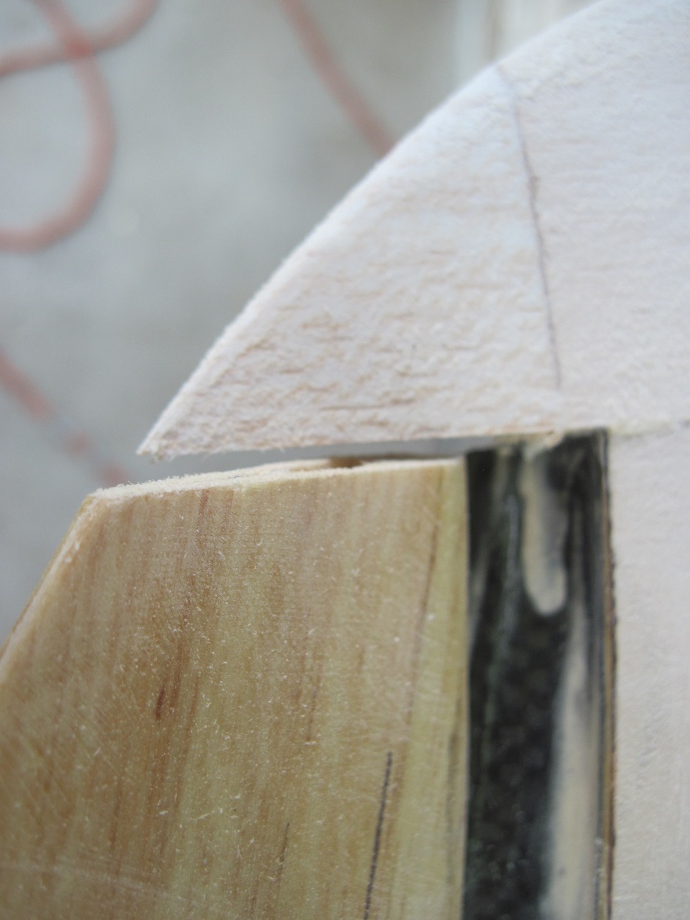
Wing tip nav lights are done.
I cut the light block out and drilled the hole to access the wire.
Then the LED holder is installed for fitting.
Wiring is hooked up and tested


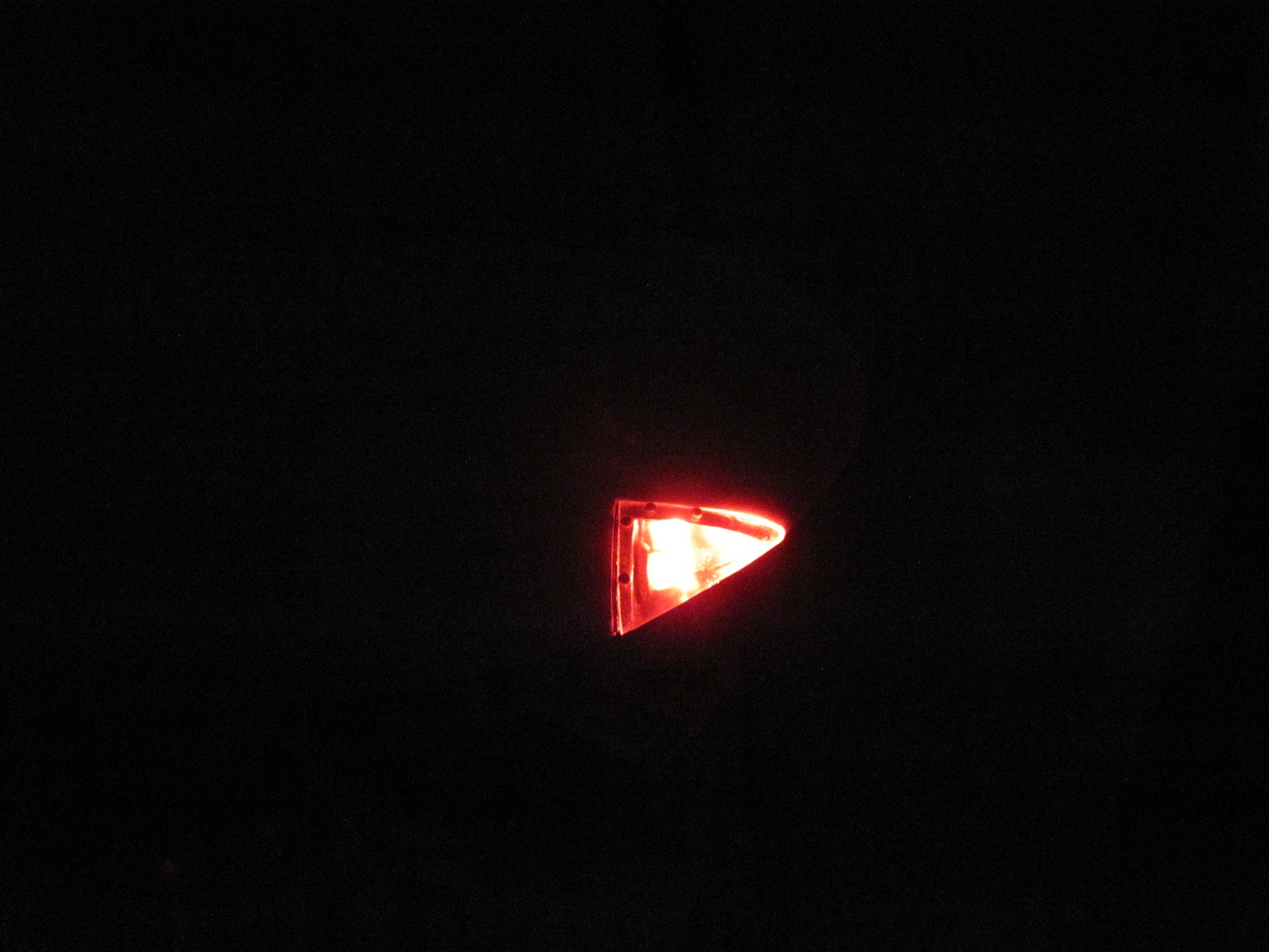
I am using 8mm 1w LEDs that come protected and will take 6v-14v directly to the LED.
My landing light is hooked up and tested, 10W 12v halogen.


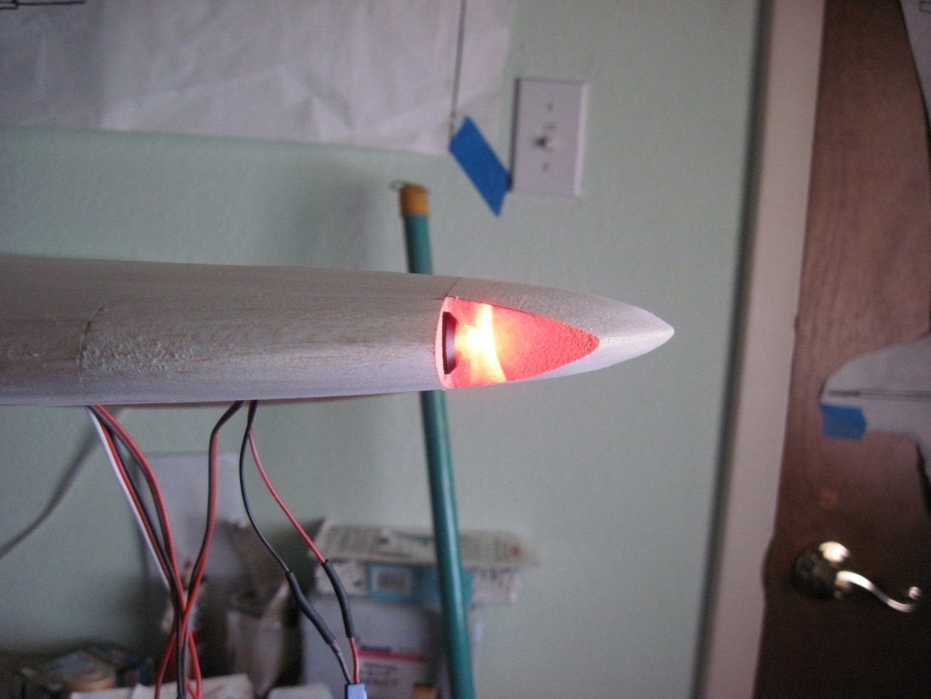
The lens was made by Chad as I do not have a vacuum former. He made them when I had him make my cub lenses.


The frame is 1/8" ply finished off with 1/64" styrene and cover with aluminum foil tape.


The 8mm 1w LEDs are nice and bright.
The lenses is cut and fitted.
.


The nav light assembly is ready to have the lens installed.
#80 button head screws hold the lens on.


I will glue in the leans frame once the wing is covered.


Next is the guns.
TB
I cut the light block out and drilled the hole to access the wire.
Then the LED holder is installed for fitting.
Wiring is hooked up and tested
I am using 8mm 1w LEDs that come protected and will take 6v-14v directly to the LED.
My landing light is hooked up and tested, 10W 12v halogen.
The lens was made by Chad as I do not have a vacuum former. He made them when I had him make my cub lenses.
The frame is 1/8" ply finished off with 1/64" styrene and cover with aluminum foil tape.
The 8mm 1w LEDs are nice and bright.
The lenses is cut and fitted.
.
The nav light assembly is ready to have the lens installed.
#80 button head screws hold the lens on.
I will glue in the leans frame once the wing is covered.
Next is the guns.
TB
Last edited by TonyBuilder; 05-25-2015 at 03:56 PM.
 05-27-2015, 01:08 PM
#2111
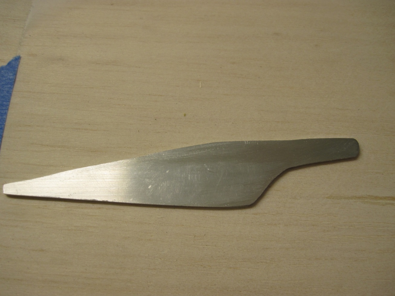
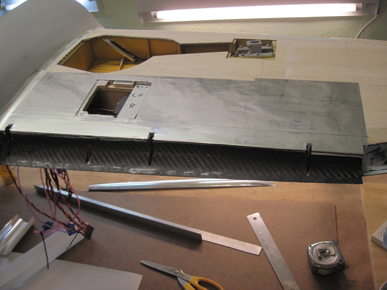
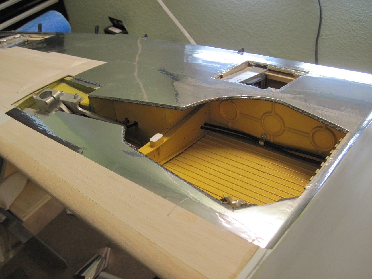
The gun plug is completed.
I am doing the guns the same way as I did the prototype.
First I cut out the area that the gun cover is located.
I then prep it for facing.


The back plate will have 8 1/4" magnets.
This gets glued in along with the side facing.


Then a balsa block is cut to size and a plate of tin is glued to the back for the magnets to grab. Two CF dowels are for alignment


Then I sand it to match the wing.


With the plug done I can cover the wing and work on the guns as time permits. I can do them when ever.


Having the guns in a plug instead of having to remove each gun and remember where they go is much easier.
I will just remove the gun plug during transport, field set up and disassembly
Installing the guns will be much easier this way as I can use my drill press and get the correct angles for the guns.
They need to be level as the plane sits, not fallowing the LE line of the wing. Thy need to be slightly pointed in not just strait forward as at some point the fire line meets up.


Now I will start to cover.
TB
I am doing the guns the same way as I did the prototype.
First I cut out the area that the gun cover is located.
I then prep it for facing.
The back plate will have 8 1/4" magnets.
This gets glued in along with the side facing.
Then a balsa block is cut to size and a plate of tin is glued to the back for the magnets to grab. Two CF dowels are for alignment
Then I sand it to match the wing.
With the plug done I can cover the wing and work on the guns as time permits. I can do them when ever.
Having the guns in a plug instead of having to remove each gun and remember where they go is much easier.
I will just remove the gun plug during transport, field set up and disassembly
Installing the guns will be much easier this way as I can use my drill press and get the correct angles for the guns.
They need to be level as the plane sits, not fallowing the LE line of the wing. Thy need to be slightly pointed in not just strait forward as at some point the fire line meets up.
Now I will start to cover.
TB
Last edited by TonyBuilder; 05-27-2015 at 01:20 PM.
05-27-2015, 05:30 PM
#2112

My Feedback: (6)
T/B
Way back when I built mine I was reading every thing I could on the 47, and from memory I think I read that the 8 gun pairs had different converging points kinda like ( don't remember the distance) 250 yds up to 300 tp match the rings in the gun sight.
Just a bit of trivia from an old gezzer
Cheers Bob T
05-27-2015, 05:44 PM
#2113
Here is some more info on the gun alignment
In aerial gunnery, gun harmonisation, convergence pattern, convergence zone, convergence point or boresight point refers to the aiming of fixed guns or cannon carried in the wings of a fighter aircraft. The wing guns in fighters were typically not bore-sighted to point straight ahead; instead they were aimed slightly inward so that the projectiles met at one or more areas several hundred yards or metres in front of the fighter's nose. The intent was either to spread the fire of multiple weapons to increase the chance of a hit, called "pattern harmonisation", or to concentrate the fire to deliver greater damage at one point, called "point harmonisation".A limitation of harmonisation was that targets closer or farther away than the effective zone were not damaged as much, or were completely missed. The rounds would diverge further apart after passing through the convergence point.
The convergence of multiple guns was a common practice from the 1930s to the 1950s, especially in World War II. Military aircraft from the 1960s onward generally did not carry guns in the wings, so convergence was not as much of a concern.

TB
In aerial gunnery, gun harmonisation, convergence pattern, convergence zone, convergence point or boresight point refers to the aiming of fixed guns or cannon carried in the wings of a fighter aircraft. The wing guns in fighters were typically not bore-sighted to point straight ahead; instead they were aimed slightly inward so that the projectiles met at one or more areas several hundred yards or metres in front of the fighter's nose. The intent was either to spread the fire of multiple weapons to increase the chance of a hit, called "pattern harmonisation", or to concentrate the fire to deliver greater damage at one point, called "point harmonisation".A limitation of harmonisation was that targets closer or farther away than the effective zone were not damaged as much, or were completely missed. The rounds would diverge further apart after passing through the convergence point.
The convergence of multiple guns was a common practice from the 1930s to the 1950s, especially in World War II. Military aircraft from the 1960s onward generally did not carry guns in the wings, so convergence was not as much of a concern.
TB
05-28-2015, 01:28 PM
#2115
Here is some more info on the gun alignment
In aerial gunnery, gun harmonisation, convergence pattern, convergence zone, convergence point or boresight point refers to the aiming of fixed guns or cannon carried in the wings of a fighter aircraft. The wing guns in fighters were typically not bore-sighted to point straight ahead; instead they were aimed slightly inward so that the projectiles met at one or more areas several hundred yards or metres in front of the fighter's nose. The intent was either to spread the fire of multiple weapons to increase the chance of a hit, called "pattern harmonisation", or to concentrate the fire to deliver greater damage at one point, called "point harmonisation".A limitation of harmonisation was that targets closer or farther away than the effective zone were not damaged as much, or were completely missed. The rounds would diverge further apart after passing through the convergence point.
The convergence of multiple guns was a common practice from the 1930s to the 1950s, especially in World War II. Military aircraft from the 1960s onward generally did not carry guns in the wings, so convergence was not as much of a concern.
TB
Sincerely, Richard
C. A. P. P-47
05-30-2015, 03:38 AM
#2116
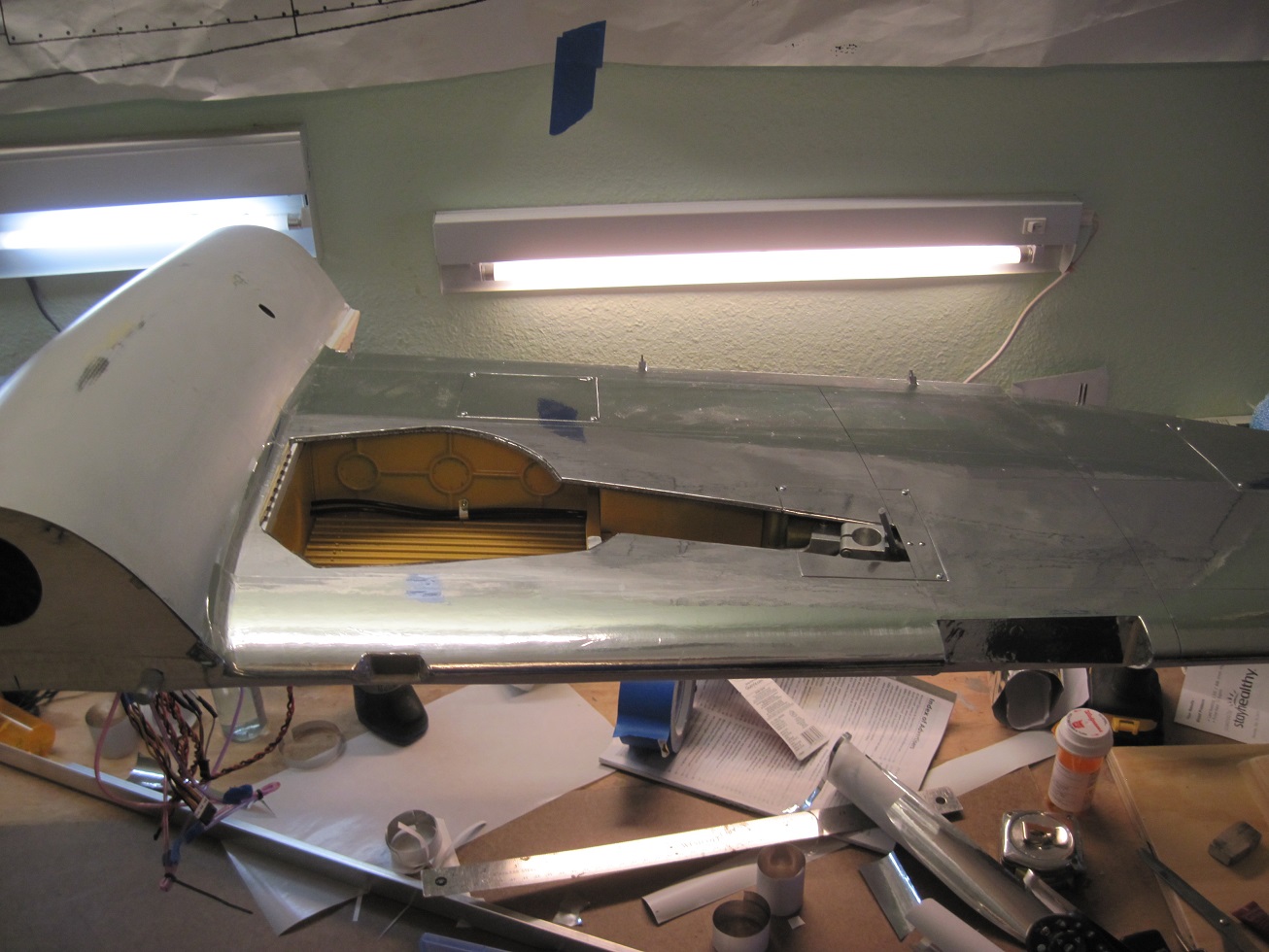
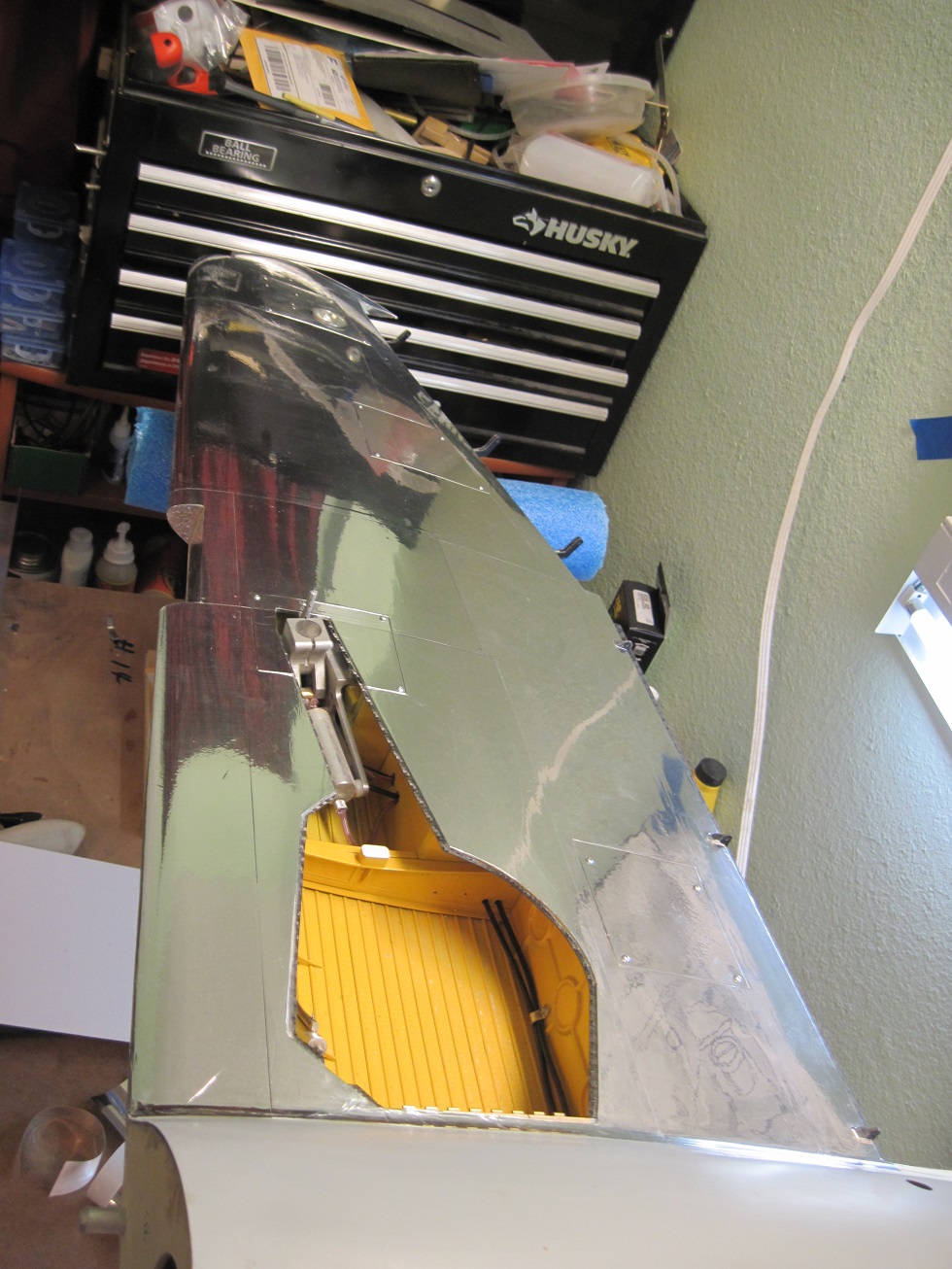
Pitot tube and air inlet are completed so the wing is ready to cover.
I used the Pitot tube from the prototype and I used a bullet connector so I can remove the tube during transport and setup. I just plug it in and I am done, no magnets or threads, we will see how this holds up.


One end is glued into the receiving tube that is glued into the wing.
The other end is glued to the tube.


Air scoop is cut in, not sure how I will finish this off, but I will do so during the covering.

Panel lines are lined out.

I am shooting to have the wing all covered today and start detailing, should have it done by the end of tomorrow.
TB
I used the Pitot tube from the prototype and I used a bullet connector so I can remove the tube during transport and setup. I just plug it in and I am done, no magnets or threads, we will see how this holds up.
One end is glued into the receiving tube that is glued into the wing.
The other end is glued to the tube.
Air scoop is cut in, not sure how I will finish this off, but I will do so during the covering.
Panel lines are lined out.
I am shooting to have the wing all covered today and start detailing, should have it done by the end of tomorrow.
TB
05-30-2015, 03:22 PM
#2117
Bottom of the wing is completed.
I am doing individual panels.


I did both sides at the same time using the pattern from one to the other.


The bottom is more complicated then the top with the gear doors and the hatches.


All screws are in for the hatches, button heads.


The top will get done in the prning the I start detailing.


TB
I am doing individual panels.
I did both sides at the same time using the pattern from one to the other.
The bottom is more complicated then the top with the gear doors and the hatches.
All screws are in for the hatches, button heads.
The top will get done in the prning the I start detailing.
TB
06-01-2015, 02:09 PM
#2120
Some more wing progress.
I am using Ultra cote brushed aluminum, and aluminum foil tape.
Alternating the grain with the covering pops the individual panels.


The wing is all covered and I think I used a total of three rolls on the wings with a good portion left.


I started detailing the wing with the bottom and realized I don't have enough product to finish the wing as I am short one stars and bars and will run out of rivets.

So I am going to finish the top first then work on the bottom until I run out of rivets.


The stars and bars for the top is to big but it is all I have as it should be the smaller size.


I am trying to get the top done today and then work on the bottom tomorrow.
I need to have the plane ready to fly by Thursday so I only get one more day of detailing then I have to put it all together and go test fly it.
I am going to bomber field this weekend so I'm in overdrive.")
I can finish the rest later.
TB
I am using Ultra cote brushed aluminum, and aluminum foil tape.
Alternating the grain with the covering pops the individual panels.
The wing is all covered and I think I used a total of three rolls on the wings with a good portion left.
I started detailing the wing with the bottom and realized I don't have enough product to finish the wing as I am short one stars and bars and will run out of rivets.
So I am going to finish the top first then work on the bottom until I run out of rivets.
The stars and bars for the top is to big but it is all I have as it should be the smaller size.
I am trying to get the top done today and then work on the bottom tomorrow.
I need to have the plane ready to fly by Thursday so I only get one more day of detailing then I have to put it all together and go test fly it.
I am going to bomber field this weekend so I'm in overdrive.
I can finish the rest later.
TB
 06-02-2015, 01:35 PM
#2124
I am trying not to, but I really need a break to do some flying.......but need a plane to fly
I'm resigned to the fact that it will be done when it's done and will most lekely not be ready to fly this weekend, if it is great, if not then next week.
TB
I'm resigned to the fact that it will be done when it's done and will most lekely not be ready to fly this weekend, if it is great, if not then next week.
TB
06-02-2015, 01:44 PM
#2125
If you are wondering, yes you can rivet yourself sick, after two days strait of applying rivets I started to get car sick, nausea set in so I took a break and installed the aileron and flap on the left wing, landing light is in along with the nav wing tip light. I painted the gear doors and will install the gear tomorrow. I only have one sheet of rivets left and Chad is going to be sending me more later this week, so I'm in setup mode now.
TB