


12' Laser-cut Telemaster Kit Build
 02-04-2014, 05:56 PM
#76

My Feedback: (23)

Join Date: Nov 2003
Location: Kinston,
NC
Posts: 47
Likes: 0
Received 0 Likes
on
0 Posts
Hey All,
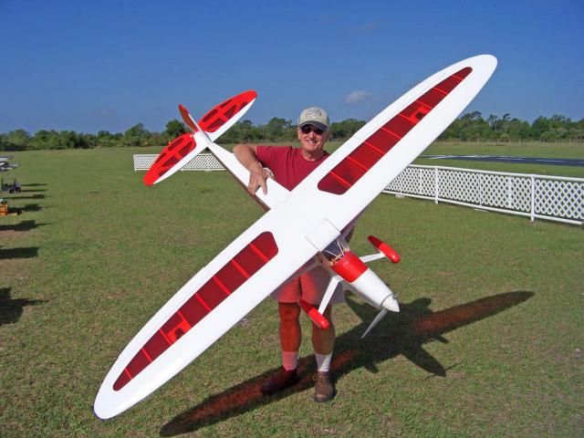
I belong to a mini horse (who is MY drinking buddy) and I give him Miller Genuine Draft and I hear no complaints...lol I grew up in Goose Bay Labrador (Air Force brat) and I have many GREAT memories from there.Heres a link to my Giant being flown by our club president https://www.facebook.com/photo.php?v=730378016987526
Telemasters have to be the BEST flying plane ever designed...
TTYL,
Bruce
 02-04-2014, 06:34 PM
#77
Senior Member

Hey All,
I belong to a mini horse (who is MY drinking buddy) and I give him Miller Genuine Draft and I hear no complaints...lol I grew up in Goose Bay Labrador (Air Force brat) and I have many GREAT memories from there.Heres a link to my Giant being flown by our club president https://www.facebook.com/photo.php?v=730378016987526
Telemasters have to be the BEST flying plane ever designed...
TTYL,
Bruce
My 3 1/2 HP high compression CDI FA180 should tow that around quite nicely.
I think they are even a little more capable than the Sr Telemaster as far as the range of the flight envelope.
http://www.rcuvideos.com/video/Erics-Rascal-mov
02-05-2014, 06:48 PM
#78
My Feedback: (23)
Join Date: Nov 2003
Location: Kinston,
NC
Posts: 47
Likes: 0
Received 0 Likes
on
0 Posts
Hey All,
I have 2 and a half Sig Senior Kadets that are great flying planes, but the Telemaster (any size) HAS NO equal in GREAT flying traits!!! I have no prior flying on the Rascal,but if she came from SIG then she'll do fine.
TTYL,
Bruce
I have 2 and a half Sig Senior Kadets that are great flying planes, but the Telemaster (any size) HAS NO equal in GREAT flying traits!!! I have no prior flying on the Rascal,but if she came from SIG then she'll do fine.
TTYL,
Bruce
02-23-2014, 06:05 PM
#79
Member
Thread Starter
Join Date: Apr 2013
Location: Brantford, ON, CANADA
Posts: 59
Likes: 0
Received 0 Likes
on
0 Posts
Good evening everyone! Rumours of my demise have been greatly exaggerated! I apologize for not posting on the forum for some time, but flying, work and home renovations have really put a damper on my building. The good news is that I have been working on the Telemaster and will be posting a lot of pictures and notes over the next day or two to get the thread caught up to where the kit is now.
Thanks!
ISF2008
Thanks!
ISF2008
02-23-2014, 06:38 PM
#81
Member
Thread Starter
Join Date: Apr 2013
Location: Brantford, ON, CANADA
Posts: 59
Likes: 0
Received 0 Likes
on
0 Posts
Next up - completing some details prior to sanding out:
- The first four pictures show adding the root rib to the fuselage sides.
- These parts were glued on using 30 minute epoxy and lots of clamps. The screws that will hold the wings from pulling away from the fuselage were used to hold the root ribs on where it was not possible to use clamps.
- The next three pics show the wings actually on the fuselage.
- The last two shots show the DLE 85 mounted on the fuselage. I had to trim one of the cheeks at the front to clear the rather large muffler. Not totally happy about this, but not much choice.
Once I mounted the anti-rotation plates (these are the clear polycarbonate spring-loaded ones that snap into slots in the wing) the wings were prevented from dropping at the trailing edge. For security I decided to add a bolt to positively secure the wings to the fuselage. I'll have to take a good picture of this and post it here.
02-23-2014, 07:14 PM
#82
Member
Thread Starter
Join Date: Apr 2013
Location: Brantford, ON, CANADA
Posts: 59
Likes: 0
Received 0 Likes
on
0 Posts
Installing the landing gear:
This post will cover installing the landing gear. The kit comes with a large formed aluminum main landing gear which weighs in at around 40oz. Even though the gear is quite large and heavy it is flimsy, and this was confirmed when the fuselage and wings were set up on the gear. It sagged quite a bit under the weight, so I could only imagine what might happen with one of my bouncy landings. Also, the gear was a bit short for the 26" prop that will be fitted. I did some searching on the internet and found a carbon fiber gear for an ARF (I guess ARF's are good for something! ) The gear was a little narrower, but taller and considerably lighter at 11oz. A quick call to Troy Built Models had one winging its way to me. The first two pictures show the size difference. The new gear is considerably stiffer and about 3" taller, so I feel confident I'm not going to damage the plane or have a prop strike on a rough landing. I had to add a filler plate and two blind nuts to the landing gear plate for the new gear. Once installed it looks great, and the wheels are in about the same spot relative to the wing as with the original gear. The wheels are from Sullivan and are 6" in diameter with aluminum hubs. The hubs have recesses in them for ball bearings so I mounted two bearings in each wheel. They roll smo-o-o-o-th...
Now that the main gear was up to snuff the stock tailwheel mount seemed inadequate. The kit is designed to have the tailwheel mounted directly on the rudder. While this is great on a 40-size plane I felt that there was too much potential for damage to the rudder and/or rudder servo with that setup. I ordered a carbon bracket to match the main gear along with a rubber tailwheel with a similar hole pattern to the main wheels. Using 5/32" wire I bent up a new tailwheel axle and mounted it to the bracket with two control arms so that I could hook it up to the rudder for steering. This new setup required that I add about 1-1/2" to the bottom of the rudder to provide somewhere to mount the control horns used to operate the tailwheel. Also, the new tailwheel assembly raised the aft of the plane up about 1", which is good given the added height at the main gear.
Next up - building the wing struts...


This post will cover installing the landing gear. The kit comes with a large formed aluminum main landing gear which weighs in at around 40oz. Even though the gear is quite large and heavy it is flimsy, and this was confirmed when the fuselage and wings were set up on the gear. It sagged quite a bit under the weight, so I could only imagine what might happen with one of my bouncy landings. Also, the gear was a bit short for the 26" prop that will be fitted. I did some searching on the internet and found a carbon fiber gear for an ARF (I guess ARF's are good for something!
) The gear was a little narrower, but taller and considerably lighter at 11oz. A quick call to Troy Built Models had one winging its way to me. The first two pictures show the size difference. The new gear is considerably stiffer and about 3" taller, so I feel confident I'm not going to damage the plane or have a prop strike on a rough landing. I had to add a filler plate and two blind nuts to the landing gear plate for the new gear. Once installed it looks great, and the wheels are in about the same spot relative to the wing as with the original gear. The wheels are from Sullivan and are 6" in diameter with aluminum hubs. The hubs have recesses in them for ball bearings so I mounted two bearings in each wheel. They roll smo-o-o-o-th...Now that the main gear was up to snuff the stock tailwheel mount seemed inadequate. The kit is designed to have the tailwheel mounted directly on the rudder. While this is great on a 40-size plane I felt that there was too much potential for damage to the rudder and/or rudder servo with that setup. I ordered a carbon bracket to match the main gear along with a rubber tailwheel with a similar hole pattern to the main wheels. Using 5/32" wire I bent up a new tailwheel axle and mounted it to the bracket with two control arms so that I could hook it up to the rudder for steering. This new setup required that I add about 1-1/2" to the bottom of the rudder to provide somewhere to mount the control horns used to operate the tailwheel. Also, the new tailwheel assembly raised the aft of the plane up about 1", which is good given the added height at the main gear.
Next up - building the wing struts...
02-23-2014, 07:35 PM
#83
Member
Thread Starter
Join Date: Apr 2013
Location: Brantford, ON, CANADA
Posts: 59
Likes: 0
Received 0 Likes
on
0 Posts
Building the wing struts:
This Telemaster, like the ones before it, has functioning wing struts. One of the complaints about the struts on the previous version of the giant Tele is that they came apart in flight from time to time due to their built-up construction. Needless to say the results of this failure were not positive.
The new kit features profiled aluminum tubes for the struts, with polycarbonate end brackets. These brackets are epoxied and screwed to the tubes so they won't pull out.
- The first step in building the struts is to clean up the polycarbonate parts and give them a light sanding so the epoxy adheres better. The brackets have holes in them so the epoxy can bond through them.
- There is a single bracket used to mount the struts to the fuselage. This is installed first. I used JB Weld to epoxy the strut tubes to the bracket.
- After the epoxy had cured the wings were mounted on the fuselage (she's a big bird!) so that the wing brackets could be installed. I had to cut 1/2" off the front strut as it hit the wing rib when in position. Once this was done the wing-end brackets were installed without glue and the strut installed on the wing. This give the proper seating depth of the wing-end bracket in the strut tube.
- The wing-end brackets were then epoxied in place. I mounted the struts back on the plane while the epoxy cured to make sure the brackets didn't move.
- Once the assembly had cured it was removed from the plane. The instructions say to drill a hole and install a small wood screw to act as an additional stop to prevent the bracket from pulling out of the wing. I went with a 4-40 bolt and nylock nut in place of the screw. In drilling the holes for the bolts I was relieved to see that there was epoxy in the filings as getting the epoxy down into the strut was a bit of a chore.
Of note is the fact that the struts are basically interchangeable as they are the same length. This means (hopefully) that the wings are identical as well!
Next up - sanding out in preparation for covering...
02-24-2014, 04:55 PM
#84
Member
Thread Starter
Join Date: Apr 2013
Location: Brantford, ON, CANADA
Posts: 59
Likes: 0
Received 0 Likes
on
0 Posts
Tonight's post shows the Telemaster all sanded and ready (for the most part) to cover. It actually took quite a few days to sand the plane out as there was a fair bit of wood to remove. As there is no leading edge upper sheeting on the tail and wing, special attention was paid to make sure that the leading edge contours matched the supplied template. Finishing generally followed these steps:
- rough shaping with a utility knife and razor plane
- rough sanding with 80 grit
- mid-sanding with 150 grit
- filing of all imperfections and hangar rash
- re-sand with 150 grit
- fill remaining imperfections and hangar rash
- touch up with 150
- sand with 220 grit on a sanding bar
- hand-sand with 320 grit
- final sand with 400 grit
Whatever dents and dings remain will simply form part of the aircraft's character, as I'm sure there will be a lot more!
I've added the pictures to the post in the general order of assembly, and will comment on each in turn.
Stab/Elevator:
- The first two photos show the stab/elevator ready for covering, with servo mounting holes drilled.
- I added some material to the front of the elevator prior to cutting in the bevels with my full-size table saw. I probably over-did the bevels...but hey, lots of elevator authority is good, right?
- In light of the over-beveled bevel, I decided to add some diagonal reinforcing to the stab and elevator in a similar fashion to the wing. This added less than an ounce to the tail, but the assembly is noticeably stiffer.
Fin/Rudder:
- The next photos show the Fin/Rudder assembly sanded out.
- You can clearly see the rudder extension I added to align the control horns on the rudder with the control horns on the fuselage-mounted tail wheel.
- The dorsal fin will be glued to the fuselage and will not be removable like the stab/fin.
Next post will be the fuselage...
02-24-2014, 05:06 PM
#85
Member
Thread Starter
Join Date: Apr 2013
Location: Brantford, ON, CANADA
Posts: 59
Likes: 0
Received 0 Likes
on
0 Posts
Fuselage:
- The first photo shows the fuselage sitting on the bench ready for covering. It is sitting on an 8' long sheet of MDF.
- The next photos show the top of the fuselage. A fair bit of filler was needed to make up for the seams in the sides and on the hatches.
- Next up is the top hatch showing the tab needed to pull it off the magnets.
- On the front hatch there is a piece of triangle stock that forms the base of the windshield. I replaced a portion of this with hardwood triangle stock as I had already knocked the corners off the original balsa stock.
- The bomb bay is next. I also made a filler plate from basswood that fits in the bomb bay opening for the times when I don't want to carry the bomb bay around. This saves about 14oz...
- The next two pics show the bomb bay and filler plate in the aircraft. I added some thin strips of balsa to the bottom of the fuse sides to even out irregularities in the laser cutting. I also changed the strut mounting hardware from screws to 6-32 cap screws and blind nuts. While I doubt that this assembly will see much actual tension the bolts and blind nuts will resist more shear than the smallish wood screws.
Next up - the wings!
02-24-2014, 05:17 PM
#86
Member
Thread Starter
Join Date: Apr 2013
Location: Brantford, ON, CANADA
Posts: 59
Likes: 0
Received 0 Likes
on
0 Posts
Wing assemblies:
- The pictures generally show only the right wing. The first picture shows the right wing on the bench.
- The next two pics show some of the inner details of the wing structure. Hardware for the strut mount plates has been removed for covering, and will be installed once the bottom of the wing is covered. The brown paper tubes are for the servo leads feeding the flap and aileron servos. I was a bit surprised that these were not included in the wing structure in the original design. The great folks at AMR hooked me up with some servo lead tubes and I mounted them to the wings and fuselage with plates made from scrap balsa (not that there was any in the kit - maybe just enough to build a 25 size trainer!)
- The next photo shows the two wings up against a door frame next to my trusty Sig Fazer.
- Flaps are next. The close-up on the flap shows the radius needed to enable the flaps to rotate almost 90 degrees down.
- The last two pics show the left wing panel with aileron and flap set in position.
Before covering there are a few small details that have to be taken care of:
- glassing and painting the inside of the cowl area
- fitting the control horns for the tail wheel
- preparing the hinge assemblies for the ailerons
That's it for tonight - next up will be the colour scheme!


- The pictures generally show only the right wing. The first picture shows the right wing on the bench.
- The next two pics show some of the inner details of the wing structure. Hardware for the strut mount plates has been removed for covering, and will be installed once the bottom of the wing is covered. The brown paper tubes are for the servo leads feeding the flap and aileron servos. I was a bit surprised that these were not included in the wing structure in the original design. The great folks at AMR hooked me up with some servo lead tubes and I mounted them to the wings and fuselage with plates made from scrap balsa (not that there was any in the kit - maybe just enough to build a 25 size trainer!
)- The next photo shows the two wings up against a door frame next to my trusty Sig Fazer.
- Flaps are next. The close-up on the flap shows the radius needed to enable the flaps to rotate almost 90 degrees down.
- The last two pics show the left wing panel with aileron and flap set in position.
Before covering there are a few small details that have to be taken care of:
- glassing and painting the inside of the cowl area
- fitting the control horns for the tail wheel
- preparing the hinge assemblies for the ailerons
That's it for tonight - next up will be the colour scheme!
02-24-2014, 05:23 PM
#87
Member
Thread Starter
Join Date: Apr 2013
Location: Brantford, ON, CANADA
Posts: 59
Likes: 0
Received 0 Likes
on
0 Posts
A couple other small points:
- In a previous post one of the members had asked about the span of the stab. I measured it at 50-3/4"
- The instructions mention that once the main wing structure is done that it is a good idea to go over all the wing joints and reinforce with additional glue. I think this step is mandatory, as there were more than several joints that looked a little starved for glue. I double-glued everything I could get at with white glue. It was a bit of a pain, but I think worth it in the long run.

 02-25-2014, 06:26 PM
#89
Member
Thread Starter
Join Date: Apr 2013
Location: Brantford, ON, CANADA
Posts: 59
Likes: 0
Received 0 Likes
on
0 Posts
Colour scheme and other small points:
First off - The filler that I used is Elmer's Carpenter's Wood Filler. I bought the big 1 quart tub. It goes on easier than the balsa fillers that you get at the hobby store and sands out about the same as the balsa. I'll keep using it for future projects.
The colour scheme has been more or less finalized and is going to be Cub yellow with aluminum and metallic grey. The windshield and side windows will be metallic charcoal.
Other items have been completed as well and make up the balance of the pictures:
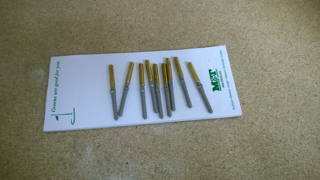
- The aileron hinges have a brass tube reinforcement as the hinges end up sticking out of the wing a little bit. The instructions say to use thick CA and accelerator, but I chose to use 30 minute epoxy mixed with milled fiberglass so it wouldn't run.
- The next photo shows an alteration made to the bomb bay. When I test-fit the radio power center in the plane I didn't like the way the whiskers routed off the receiver. Cutting an inch off the top of the bomb bay assembly enables the receiver to sit below the wing latch plate, so the whiskers can run straight out under the plate.
- Remaining photos show the area under the front hatch. I use #64 elastic bands to hold down the fuel tank. The firewall was reinforced with hard ply in way of the blind nuts so that they wouldn't draw into the softer firewall and cause the engine to loosen. The hole in the bottom right of the picture is for the spark plug lead and hall effect sensor lead. The last photo shows the plywood disk that I installed in the side of the fuselage for the remote fueller.
That's it for tonight!
Next up - covering starts!


First off - The filler that I used is Elmer's Carpenter's Wood Filler. I bought the big 1 quart tub. It goes on easier than the balsa fillers that you get at the hobby store and sands out about the same as the balsa. I'll keep using it for future projects.
The colour scheme has been more or less finalized and is going to be Cub yellow with aluminum and metallic grey. The windshield and side windows will be metallic charcoal.
Other items have been completed as well and make up the balance of the pictures:
- The aileron hinges have a brass tube reinforcement as the hinges end up sticking out of the wing a little bit. The instructions say to use thick CA and accelerator, but I chose to use 30 minute epoxy mixed with milled fiberglass so it wouldn't run.
- The next photo shows an alteration made to the bomb bay. When I test-fit the radio power center in the plane I didn't like the way the whiskers routed off the receiver. Cutting an inch off the top of the bomb bay assembly enables the receiver to sit below the wing latch plate, so the whiskers can run straight out under the plate.
- Remaining photos show the area under the front hatch. I use #64 elastic bands to hold down the fuel tank. The firewall was reinforced with hard ply in way of the blind nuts so that they wouldn't draw into the softer firewall and cause the engine to loosen. The hole in the bottom right of the picture is for the spark plug lead and hall effect sensor lead. The last photo shows the plywood disk that I installed in the side of the fuselage for the remote fueller.
That's it for tonight!
Next up - covering starts!
02-25-2014, 06:52 PM
#90
Senior Member
As I suspected, the stabilizer has anough span for a .40 sized aircraft.
03-02-2014, 07:02 AM
#93
My Feedback: (23)
Join Date: Nov 2003
Location: Kinston,
NC
Posts: 47
Likes: 0
Received 0 Likes
on
0 Posts
Hey All,
I'm also glad to know that everything is alright up there!!! I just got caught up on your super build as I haven't had time to get on here to play..You know how life gets in the way of having fun...lol Thanks for the tip on Elmer's Carpenter's Wood Filler, I'll have to get some for my next build. My bomb bay is built in and is quite large but we can drop a lot of strange things...LOL Please keep up the good work and I like your covering ideas. You'll be amazed at the amount of covering used,but much easier to do than on smaller planes.
TTYL,
Bruce
03-03-2014, 08:08 PM
#94
Member
Thread Starter
Join Date: Apr 2013
Location: Brantford, ON, CANADA
Posts: 59
Likes: 0
Received 0 Likes
on
0 Posts
I have been back and forth on engine choice for some time. Hobby Lobby's prototype had an OS GT55 for power. At least one other modeler has put a DLE55 on the airframe. My initial thoughts were to put a DLE 85 on the plane as the extra weight would help balance the plane and be productive at the same time. Also, I was a little concerned about a lack of power. Some research along with input into this thread has made me question my choice. Watching a video of the new kit flying in a convincing manner powered by a DLE55 has changed my mind on engine size. Also, I weighed the aircraft and all components and came up with an all-up weight estimate of 27lbs net of ballast and fuel. This is several pounds lighter than the weights reported by other modelers (seems to me that people are getting around 33lbs AUW). I have decided to mount a DLE55 with Pitts style "ultra quiet" muffler.
The engine needs to be mounted as far forward as possible to help balance the plane. I cut one of the cheek cowls to make room for the large muffler on the DLE85, so now I was faced with the task of repairing the side of the fuselage. Realizing that I would likely have to add some weight to the nose anyway I decided to build a full cowl for the DLE55. I have attached some SolidWorks images of the plane with the cowl mounted. It doesn't quite fit 100%, but this is because my SolidWorks fuselage is not exactly the same as my actual fuselage. The cowl definitely cleans up the front of the plane and makes it look sleeker. A carbon spinner and prop will round out the "high tech" look.
The remainder of the images show the cowl on its own. The design consists of a light-ply or ply framework with 1/8" balsa sheeting. The cowl is split horizontally on the crankshaft line so can be removed from the plane without removing the prop. The cowl will be held on with a combination of magnets and locating dowels.
I'm going to build the cowl and motor box before I start covering the fuselage.
More pictures to follow!
03-04-2014, 08:10 PM
#98

I have been following your build, it looks great, keep up the good work.
Mine had a DLE 111 for power, it was a older stick built one that had been reinforced and had heavy aluminum struts for carrying R/C skydivers.
It was set up to carry 5 @ 3-4 lbs. each. The plane weighed 43 lbs.
However it met it's demise last fall with an encounter with a WV tree.
Fixing it was suppose to be my winter project, but winter it almost gone and I haven't started.
03-05-2014, 03:32 PM
#100
Junior Member
Join Date: Nov 2007
Location: Waterford,
ON, CANADA
Posts: 21
Likes: 0
Received 0 Likes
on
0 Posts
Gary, could you tell me about the sky divers- I looked into it a while back but didn't see any suitable options. My thought was to convince the builder of this here airplane- a member of my club and good guy- to provide a ride for one which I'd supply and control. Might as well use this large airsraft for something useful, right? I haven't broached the subject with him as yet but here it is,,,
Tom
Tom