


AMR 100" Twin 30cc powered kit

 05-21-2014, 12:12 PM
#52

Hey Bob, one thing you might consider. I've never been able to sync my engines through the entire rpm range. I usually get them close at 3/4 throttle and full throttle. I've used throttle curves to get the close through the whole range of throttle but it seems weather etc. always cause the engines to run at different RPM's. I get tired of screwing around with the throttle curve and typically just use my rudder to correct for uneven yaw.
I've been thinking what we need is a gyro for this bird. A gyro on the rudder would take care of any yaw issue caused by the engines not being synced. Have not used a gyro before but something you might want to consider on your build.
Why don't you try it first and tell me how it works out for you.
Jerry.
05-21-2014, 11:01 PM
#53
Aloha JBarnes,
That is a possibility, but not sure yet if I'll include a yaw dampener. I do have an Eagle Tree auto pilot, but I will be using a "Yellow Power Box" with this airframe and I'm not sure just how well all the electronics will work together. I've had good luck here at sea level, tuning my gas engines, but to be honest, I've never had to tune two gas engines together before. I do have a place to put the Eagle Tree auto pilot, and I wonder if I can just hook up the rudder servo to it. We will see what develops as the build goes.
I did install a after market throttle carburetor control horn on my F6F (PTE36R), the red one that Troy Built Models sells. I also matched the length of the red throttle control horn, with my servo arm on my throttle and I was able to get a more linier throttle response. I may need to use a throttle curve on the engines to get a linier response and a buddy of mine did this with his engine. The out come was a really smooth throttle to his gas engine, equal to the throttle stick on his DX8. I have a DX18 and plan on doing the same, with each throttle with its own channel...and match the curve's to both throttle channels.
Today I managed to get the aft floor FF6 in step 56~60 installed. I also installed sub floor FT5 between bulkhead F2 & F3, all were glued in with 30 minute epoxy.
At this place in the build, I glued in my aft elevator servo doublers, onto the left and right fuselage sides.
I thought I had more then enough clamps for this build...but no where near enough for a model of this size.
I've my removable elevator worked out and how I'm going to mount my rudder servo. This I'll deal with tomorrow.
Today I took the little lady out for a picture taking drive around the south end of the island and had a really nice day.
Soft Landings Always,
Bobby of Maui
Last edited by Bob Paris; 05-23-2014 at 12:30 PM.
05-23-2014, 12:08 PM
#54
Aloha,
In step 62, you will bond a 3/8" square strip of balsa, on the right and left, top sides of the fuselage, to each bulkhead upper side corner, from bulkhead F4 to past F8 to the tip of the aft fuselage. The instructions really do not tell you how far aft to glue the 3/8" square balsa strip. I chose to glue it as far aft as I could and your given enough balsa to do this too. I used Tightbond III for this step. I did the right fuselage side first.
At this time I glued in forward fuel tank cover plate and access door, FT2 and FT3. If you aligned this part properly when you glued in both fuselage sides, this piece will just drop in place. I used slow cure epoxy for this step.
Next will be the rudder servo mount instillation, w/access door, between bulkhead F6 and F7.
Soft Landings Always,
Bobby of Maui
Last edited by Bob Paris; 05-24-2014 at 12:17 AM.
05-24-2014, 12:14 AM
#55
Aloha,
This after noon I installed the 3/8" sq. balsa onto the left upper inside of the fuselage per step 62 and began the prep and dry fit the top aft fuselage, FT1, in step 63. This is a crucial step so I am making sure the fit is good and the aft structure of the fuselage is square. The manual states in step 65, that this is a critical alignment-so I'm taking some time to make it right.
I cut and installed the cross pieces of 3/8" balsa, per step 66 and I will be covering this area of the forward upper wing with 1/64" aircraft quality plywood, not just a fabric or plastic covering, as the kit calls out for. This kit is big and want the added support in this area.
where and how to install my rudder servo, for rudder control and tail wheel steering has been giving me a bit of concern. I first wanted to install my rudder servo aft near the tail section, but then was stumped in how to control my tail wheel steering with the servo back aft. Then a light went off in my head...and realized the kit was designed for the rudder servo to be mounted aft under the wing...where the kit gives you a place to put the rudder servo, and run two sets of Pull-Pull cables from this rudder placement. It would be a simple thing to set up and I've used Pull-Pull cables before without any problems. So I will locate my rudder servo, under the wing, in the aft wing bay.
Soft Landings Always,
Bobby of Maui
Last edited by Bob Paris; 05-24-2014 at 11:55 AM.
05-27-2014, 08:43 AM
#56
Aloha,
I have the top aft fuselage piece emplaced per step 65 and I've fit WA1/WA2, WA5 & WA6. I will epoxy these in next and I will begin to cover the top of the fuselage per step 72 ~ 75.
There was one thing that I was not able to find in the instruction book, and that was the C.G. location and control throws required for the first flight. If anyone has these numbers, I would appreciate the information.
If you look at the first picture, you will see where I've inset three more blind nuts, one more 8/32 and two 1/4-20 blind nuts. This will facilitate locking the removable horizontal stabilizer. I placed on 1/4-20 forward of bulkhead #8, under a floor of light ply and epoxied in place.
I have ordered extra wood for the nose piece and as soon as I finish the step 75, I will be building my nose piece. For a twin...this is one place where the kit leaves it up to the builder to work out.
Soft Landings Always,
Bobby of Maui
05-27-2014, 02:24 PM
#58
Hay JBarnes,
I would change the title of the thread to AMR Twin...but do not know how to do the change. I sent an e-mail to RCU to get the fix in, on the threads title.
Do you have the C.G. balance point for the 50cc AMR stick or the control throw limits?
I did a search for yaw dampeners and there are several out there, and two, under $50.00. So installing a yaw dampener is a possibility for this airframe. I'm also considering the Eagle Tree auto pilot unit I have on hand-but I've never used one and have no idea if it will work on this size model.
Soft Landings Always,
Bobby of Maui
Last edited by Bob Paris; 05-27-2014 at 09:38 PM.
05-27-2014, 02:38 PM
#59
Aloha,
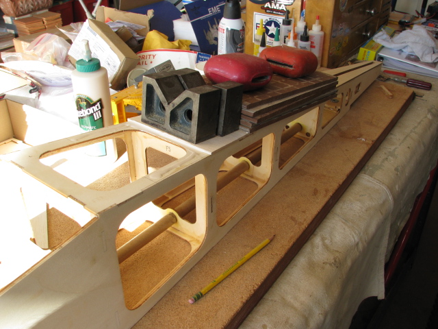
Today I epoxied the port wing support into the central wing bay. Part numbers WA1, WA2, WA5 & WA6. I trial fit first, then I used slow cure epoxy and set them into place. After the port side dries, I'll do the other side. I also did a bit more sanding, after removing the clamps to the top aft fuselage former, FT1 I glued in yesterday.
If you look at the second picture, you will see that I roughed up the area a bit where the main wing hold down pieces, WA1 ~ WA6 will be epoxied to the sides of the fuselage. I did this to give the epoxy a better hold in this critical area. I did coat this area with water based urethane, and I wanted to get below this coating, so the wood pieces had a better grip to the epoxy. I wasn't sure if I needed to do this or not, but decided to be a bit cautious in this step. The last thing I want to do is lose a wing in flight.
Next I will begin my nose piece, then cover the top fuselage with balsa sheeting per step 72 ~ 75.
Soft Landings Always,
Bob Paris
05-27-2014, 09:33 PM
#60
Aloha,
I finished installing the main wing hold down brackets, WA1 ~ WA6. The test fit went quickly and the parts fit is good. I used slow cure epoxy here and clamped every thing down. If you notice in the pictures, these parts slant forward in the fuselage...and how its installed. After this was set up, I sanded down inside the wing bay, and the top fuselage, aft piece, FT1. I've been cleaning up the gluing process and getting the fuse ready for covering.
I then used thick CA and glued on a piece of 1/64 ply, over the four 3/8" sq. wood, where the wing leading edge will connect to, and over the landing gear, forward wing hold down braces are. You may want to wait before you cover this forward part, until the wing is built...check your build manual.
The forward fire wall, F1 is 6-3/8" sq. I cut a sq. piece of 1/4" light ply, 3-1/2" sq. and will make this my new nose piece. It will sit, 7" forward of the fire wall and the bottom will angle up to meet the new nose piece. I will then laminate balsa planks on the new nose piece, to make a nice rounded nose. My nose will be mounted permanently to the nose of the model and will blend in from both sides, as well up from the bottom. I may install a hatch on the bottom floor piece of light ply, to add any lead to balance the model.
I also plan on moving my engines out by 1/2" increments, to get a balance, without adding lead. I may go as far as 2" and I plan on using 1" sq. x 5" long, aluminum. If anyone has any suggestions about this, please feel free to speak up and let me know. But so far, this is my plan.
The fuse is almost finished, and then on to the tail feathers. I ordered all my wood to build my stab and rudder and building the nose, while waiting for the balsa to arrive. The last thing on the fuselage I will do is, add the 1/8" balsa sheet. I'm concerned about hanger rash...so this will go on last, then I'll cover the fuselage.
Soft Landings Always,
Bobby of Maui
Last edited by Bob Paris; 05-28-2014 at 08:35 AM.
05-28-2014, 08:33 AM
#61
Aloha,
I just received an e-mail from AMR, stating that the C.G. for the 106" Giant Ugly Stick Twin is "7 inches" aft of the leading edge.
They also told me, to use 1-1/4" up and down for the elevator and ailerons. And personally, I'll take all the rudder I can get.
Can anyone confirm these numbers ?
Soft Landings Always,
Bobby of Maui
Last edited by Bob Paris; 05-29-2014 at 10:25 PM.
05-28-2014, 10:42 PM
#62
Aloha,
Today I cut out the beginning of my nose piece. The kit doesn't furnish any material or set up, for this twin, so its every man for himself. This is my rendition of a nose section. It is made out of 1/4" light ply and I will epoxy the two sides and top piece onto the firewall, before I install the bottom piece. I'll install a bottom piece, with an access door last-then get on to building my tail feathers. That's the plan...
Soft Landings Always,
Bobby of Maui
Last edited by Bob Paris; 05-28-2014 at 10:45 PM.
05-29-2014, 08:48 PM
#63

Bob Reading the engine sinc concerns made me think or wonder if Smartflys dual servo control would work on that issue. If they are tuned at a given RPM thats about as close as you can get, the rest is throttle position and Smartfly should get you real close. Just a thought.
Plane is coming along, I like the part where you get to figure a few things out yourself, keeps the mind sharp.
Leroy
Plane is coming along, I like the part where you get to figure a few things out yourself, keeps the mind sharp.
Leroy
05-29-2014, 10:54 PM
#64
Hay Leroy,
I'm not aware of what "Smartflys Dual servo control", is. Can you enlighten me on the issue? I know about the twin sync, but I've also read that there have been issues with that unit, with gas engines. I do have a twin sync I was going to put into a P-38, but the when I received the kit, it was unbuildable. So that is an option...but question its use in this application. A rate gyro makes more sense...for Yaw, but I'll wait until the airframe is built and all my electronics are installed. I'm running a yellow power box, and two 3300 mha, batteries I picked up from Magnum RC. I've run these before and they work well. Plus the Yellow Box has pick ups for dual batteries + a volt meter/on-off switch.
I am running two channels for my engine throttle controls and I can play with each engine's curve with my Tx. I know its important to get your engines in a reasonably good sync, with throttle up on take off, but I managed to do this well enough with my nitro engines. I know I will need to bench run the engines and get them properly broken in and tested, before I install them and attempt to fly the model. I will also run a choke servo to each engine as well as a engine kill switch for each side (a Tx operated engine kill switch is a club requirement to fly a gas engine model at our flying field).
I've ordered a external arming switch for each engine starter too. I will not arm the starters until I'm ready to start the engines, for flight. I have a concern that the starters may engage, by accident and a safety check for me. With out the arming switch in, the engines will not be able to turn over, electrically. I plan on installing two electronic engine tacks too, though my ear is good, a tack takes all the guess work out of the equation.
As I'm building this airframe, I'm also trying to think of what I will need to install and get the structure ready to accept, while I'm building the model.
Its coming along...
Soft Ladings Always,
Bobby of Maui
Last edited by Bob Paris; 05-29-2014 at 10:56 PM.
05-29-2014, 11:04 PM
#65
Aloha,
I managed to get my nose piece started and epoxied in place. I also cut a 3" diameter hole into the fire wall, for access to the nose piece structure. I did this first, but the first attempt to drill the hole...the inner bit broke and made a small mess of the fire wall. I did get a good hole cut and then proceeded to epoxy on both verticals and the top piece. I will build the floor to the nose tomorrow and build in a access plate too. I will plank the forward nose piece and round it out and blend it to the added nose section.
After the new nose section was on...I'm not sure exactly what I have. It looks kind of different and weird...for now anyway. Time will tell.
Soft Landings Always,
Bobby of Maui
05-30-2014, 08:20 AM
#66
Bob the Smart-fly products have a very good reputation, they are used in almost all IMAC planes to set up every surface control and regulate voltage, there may be one specific to twin engines but I don't know that for sure. The one I have in mind ia an equalizer control for aileron and split elevators and allowes for precise throws and alignment of two servos with one channel lead eliminating set up through the radio. You have alot to control with the starters and all and I can see your concerns getting all that set up. We have a guy with a P-38 with two 35cc engines in it and they run beautifully together and I know there is Smart-fly in the plane.
Check out their line up and see if they can offer something to help you with yours. www.smart-fly.com/product/E.../equalizer.htm or just www.smart-fly.com
Leroy
Check out their line up and see if they can offer something to help you with yours. www.smart-fly.com/product/E.../equalizer.htm or just www.smart-fly.com
Leroy
05-30-2014, 09:52 PM
#67
Hay Leroy,
I went over to Smart-fly and took a look at what they have. It was interesting, but wonder if your buddy with the P-38 used a equalizer with his engines...or just took the time to properly break them in and set them up.
It is time consuming, especially if you do it mechanically with servo and carburetor arms. My RCG 20's had a very uneven throttle response from idle to full throttle. But when I added an extended longer carburetor arm and adjusted my servo throttle arm, I was able to get a more linear throttle response. I plan on doing the same with my EME 35's. I plan on placing them on one test bed together and get them matched. I will strive for an equal spool up and that may take a few hours running time and testing. I live at sea level and so most day's temps do not change much more then five to ten degrees...not like on the main land where temps can change drastically over the day. Having a dependable idle and nearly matched spool up to full throttle and an close full throttle rpm is my goal. I've had really good luck with my nitro engines...but as I stated earlier, I've never had the experience with twin gas engines.
I understand its important with digital servo's, to get your servo's equally matched. I use HD1501BBMG servo's and they are not digital servo's. Also...none of my control surfaces have dual servo's, where a matched pair is very important, and though my elevator has two servo's, the elevator is split, each half with its own servo.
I'm going with a Yellow Power Box and this is the first time I'm using this type of electronics. All my flight controls well go through the Power Box, but my engine controls will not. The Yellow Power Box only has 8 channels and I need 7 channels along (two throttle, two choke, two electric start and one channel for engine kill). Two for ailerons, two for flaps, two for elevator and one for flaps. I will use 14 channels altogether and possible one more for a bomb drop feature. That is a lot of wires, going to a lot of places and a transmitter set up that will take some time to get perfect.
I'm still considering a rate gyro on Yaw.
Soft Landings Always,
Bobby of Maui
Last edited by Bob Paris; 05-30-2014 at 10:08 PM.
06-02-2014, 02:11 AM
#69
Aloha,
Today I managed to get my nose finished...and I'm not in love with it. I may change if, but for now...its going to stay. I did a bit of finish sanding on the fuselage and put my wheels onto the gear legs. I installed DuBro 6" pneumatic tires and installed the landing gear onto the model. Last I installed the tail wheel and placed the model on its legs for the first time. The fuselage is a bit larger then I envisioned when ordering the kit, but I'll deal with that and continue to march.
Next I'll draw out my rudder and stab...and get started on building these up. After these are built and temporarily installed, I'll set up all my electronics into the airframe and get the fuselage ready to cover.
Soft Landings Always,
Bobby of Maui
 06-02-2014, 09:37 PM
#71
Aloha,
Today I demounted my landing gear, and began to get the fuselage ready for covering. As soon as I'm finished this, I will go onto the last part of the fuselage build. From step 72 ~ step 75, you will be adding 1/8" balsa sheeting to the top of the fuselage (only the top). The forward hatch has balsa sheeting already cut for you and on the very tail end of the top fuselage, you install top piece FT7. From FT7 forward to bulkhead F4, lay additional supplied 1/8" balsa sheet cross grain, onto the top of the fuselage.
After this is done, your basic fuselage is finished, sans, the instillation of your electronics, and covering.
Next they have you build up the vertical and horizontal tail sections, to the airframe. The pictures do get a little thin here, but its a no brainer. The instructions could use a couple of pictures for clarification, but just my opinion. I'm going to be using some of the kits supplied balsa, for my tail section build, but I'm making a different tail outline. My balsa order has arrived today, so by weekend-with any luck, I should be into the their build up sequence.
The Sunset tonight was awesome...
Soft Landings Always,
Bobby of Maui
Last edited by Bob Paris; 06-02-2014 at 09:42 PM.
06-04-2014, 12:08 AM
#72
Aloha,
I finished covering the aft top of my fuselage with 1/8" balsa sheet. Its set up in sections and installed the balsa sheet cross grained. I also made sure my sheets butted up to each other, on the bulkhead cross pieces, of the light ply, FT1. By butting up at these cross pieces, I believe your butt joints will be stronger- I had to cut short, two pieces of sheet balsa to make all the joints hit the cross pieces. FT7 was a perfect fit, with just enough over run on the sides, to sand a perfect edge... : ) After FT7 was glued on, I cut and glued on the cross pieces of balsa sheet.
Next is the forward nose area, and hatch. These also get covered in 1/8" balsa sheet, step 73.
After this...its on to the vertical and horizontal tail pieces.
Soft Landings Always,
Bobby of Maui
Last edited by Bob Paris; 06-04-2014 at 12:18 AM.
06-06-2014, 11:07 PM
#73
Aloha,
Today I managed to get to work on the forward fuel tank hatch cover. The first thing I did was install the 4/40 blind nuts into four places, shown in step 67. After I installed the blind nuts, I fit the light ply, laser cut fuel tank cover and witnessed how the screw holes lined up to the emplaced 4/40 blind nuts. I needed to make a slight elongated hole in three places (on FT4), and then was able to screw the top cover into place. I then took the laser cut 1/8" balsa sheet pieces (H10, H7,H4 & H2) given to you, and glued them onto the light ply, forward fuel tank cover, FT4.
After these dry I will glue 1/8" laser cut balsa wood, pieces, H10, H8, H9 and H1, onto the outer perimeter of the fuel tank removable cover. I will also extend the 1/8' sheet balsa to the nose area I built up for the model.
The last thing I did was turn the model over onto its back, and used thin CA glue, and saturated the bottom side of the 1/8" sheet balsa I covered FT1 with. There are openings you can get at, and when this dries, will substantially strengthen the under side of the 1/8" balsa sheet, and adds no weight. I turned a fan on and ventilated the area , while the thin CA glue was drying. CA fumes suck big time and I always ventilate well any area I'm using this type of glue in.
Soft Landings Always,
Bobby of Maui
Last edited by Bob Paris; 06-06-2014 at 11:13 PM.
06-07-2014, 11:12 PM
#74
Aloha,
Today I finished gluing on the 1/8" sheet balsa on the upper forward fuselage. All I need to do now to finish the nose is to sand the filler I have placed on a couple of area's to give the top nose a nice flat look.
AMR has you use four 4/40 blind nuts, alien head screws and washers to hold the forward hatch cover onto the fuselage. After some thought I decided to make a modification to the kit, and only use two 4/40 alien head screws to do the job. I've done this mod on many models with no issues and its simple and solid. I put a lip on the forward edge of the hatch cover and this holds down the forward hatch. I needed to put in a spacer, and recess the spacer a 1/4", then over the spacer, glue on a hold down tongue. Worked like a charm and tomorrow I will finish sanding the nose section.
The last thing I did was reinforce the area where the 4/40 screws go through the 1/8" sheep balsa. The 1/8" balsa sheet is just to soft to take the torque of 4/40 screws, with out leaving an impression on the balsa sheet. In time it will not look clean, so to keep this from happening, I covered the area where the screws go through, with 1/64 quality plywood. Its very thin, will strengthen the area and keep the area looking good.
Tomorrow I will begin my rudder build up.
Soft Landings Always,
Bobby of Maui
Last edited by Bob Paris; 06-09-2014 at 11:46 AM.
06-09-2014, 12:04 PM
#75
Aloha,
I started on the vertical and horizontal stabilizers today and I ran into my first issue with the kit's laser cutting. Some of the 3/8" laser cutting latterly falls out of the 3/8" sheet balsa its cut from...other parts not properly cut through with the laser cutting. Both the vertical stab and rudder needed to be hand cut, out of, the 3/8" balsa sheet. I used new #11 blades, took my time and cut all the pieces out. It took me about an hour, being carful, and got the job done. The parts fit is good.
If you look at the second and third picture, you will see that the top part shows the outline of the cut and that the laser cut is clean. Yet when you turn the part over in the third picture, you can see that they didn't cut all the way through with the laser.
For the vertical stab, you will have six (6) parts, F11A, F11B, F12, F13, F14 & F15. This is step 81 in the manual.
For the rudder you will have four (4) parts, R1, two each R2's & R3. This is in step 80 in the manual.
The balsa sheet used is of good quality and not to soft. I am now figuring out just how I will modify my vertical stab and rudder, but I should have it done today. This is one very large rudder, but I will be making mine just a bit higher and shaped like the one you see on a mosquito twin bomber. I will not be doing a twin rudder like I first felt, and to be honest, I'm concerned about being to tail heavy with a twin rudder and twin servo's that far aft, on the model.
I did call AMR about the laser cutting on this model and I was told that its nearly impossible to get an even density 3/8" sheet balsa. And that 3/8" sheet balsa, when cut with a laser, can catch fire very easily, so they don't use a high enough setting when cutting 3/8" sheet, to preclude any wood catching fire during the cutting procedure. I talked to Dan at AMR, and he was very fourth coming and explained to me the laser cutting issue I had with my model. He stated that smaller thickness balsa sheet is not an issue, but anything thicker then 3/8" will cause problems.
Soft Landings Always,
Bobby of Maui
Last edited by Bob Paris; 06-09-2014 at 12:10 PM.