


Meister scale P-47 D-25 Diary of a scale build
 11-15-2015, 01:00 PM
#101

More progress.
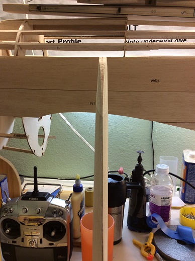
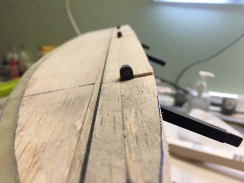
One last check on alignment before I glue the rod in.


I was thinking on how would be the best way to attach the third hinge and have it be well secured and easily removed.
So I am attaching it to a plate that I can during the install bolt that to the stab. There will be two plates so the halves will remain separate.
Template is ply, I tap threaded 2-56 button head screws.

The final piece will be carbon fiber laminates.


The rod is glued in and drying. I will cut it after it dries. This will help keep it aligned during the gluing.

TB
One last check on alignment before I glue the rod in.
I was thinking on how would be the best way to attach the third hinge and have it be well secured and easily removed.
So I am attaching it to a plate that I can during the install bolt that to the stab. There will be two plates so the halves will remain separate.
Template is ply, I tap threaded 2-56 button head screws.
The final piece will be carbon fiber laminates.
The rod is glued in and drying. I will cut it after it dries. This will help keep it aligned during the gluing.
TB
 11-17-2015, 04:36 AM
#102
Progress.
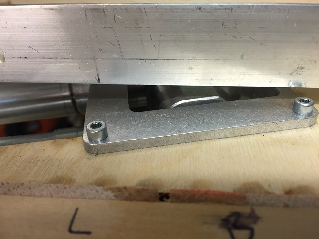
For the hinge plate I set in some aluminum hard points so I can tap thread in the screws that will hold it on.
The plate is carbon laminates glued to 1/32 ply


This will get trimmed after the pocket is down then screwed down to the TE.


The pocket is carbon fiber strips glued in with thin CA, square stock reinforces the strips.


The pocket is relatively easy to install.


I will cut in the tabs next.


Pocket is done.

TB
For the hinge plate I set in some aluminum hard points so I can tap thread in the screws that will hold it on.
The plate is carbon laminates glued to 1/32 ply
This will get trimmed after the pocket is down then screwed down to the TE.
The pocket is carbon fiber strips glued in with thin CA, square stock reinforces the strips.
The pocket is relatively easy to install.
I will cut in the tabs next.
Pocket is done.
TB
Last edited by TonyBuilder; 11-17-2015 at 04:59 AM.
11-19-2015, 04:29 AM
#103
Progress
My new radio came yesterday! Now I will have enough channels to program this puppy.


I installed the first tab (prototype).
First I recessed a notch in the TE where the tab will go.

Then I attached the tab to the aluminum plate with three #72 button head screws.
The CF strips are for alignment during the glue in.


Once glued in I added a strip of CF to create the pocket line for the tab. Sanded flush with the skin.


Tab one done. 7 more to do!


TB
My new radio came yesterday! Now I will have enough channels to program this puppy.
I installed the first tab (prototype).
First I recessed a notch in the TE where the tab will go.
Then I attached the tab to the aluminum plate with three #72 button head screws.
The CF strips are for alignment during the glue in.
Once glued in I added a strip of CF to create the pocket line for the tab. Sanded flush with the skin.
Tab one done. 7 more to do!
TB
Last edited by TonyBuilder; 11-19-2015 at 04:37 AM.
11-26-2015, 07:38 AM
#104
Happy Thanksgiving all!
Progress.
I am starting on the rudder and fin.
I got the rudder framed up and cut in the TE G-10


I will sand this down once the skin is on to a sharp edge.


Hinge blocks are in.


LE is glued in and drying


Skin will go in next.
TB
Progress.
I am starting on the rudder and fin.
I got the rudder framed up and cut in the TE G-10
I will sand this down once the skin is on to a sharp edge.
Hinge blocks are in.
LE is glued in and drying
Skin will go in next.
TB
11-27-2015, 09:53 AM
#107
Progress.
I added some balsa blocking for the trim tab, this way I can just cut it out after glassing and face it as the hard point will already be in.

Sheeting is on. I used 3/32 instead of the recommended 1/16 balsa for the skin. I think 1/16 is to thin and I like to be able to sand to fit .


Tips on and rough shaped.


Bottom blocking is in and rough shaped. I wont finish it until I install it so I can sand it to the read of the fuselage.


Onto the fin.
TB
I added some balsa blocking for the trim tab, this way I can just cut it out after glassing and face it as the hard point will already be in.
Sheeting is on. I used 3/32 instead of the recommended 1/16 balsa for the skin. I think 1/16 is to thin and I like to be able to sand to fit .
Tips on and rough shaped.
Bottom blocking is in and rough shaped. I wont finish it until I install it so I can sand it to the read of the fuselage.
Onto the fin.
TB
Last edited by TonyBuilder; 11-27-2015 at 10:06 AM.
11-29-2015, 01:19 PM
#109
I started on the right wing.
Its all famed up.


G_10 is in got the TE at the flap.

I had to do a bit of leveling as the wing was all up and down as the sizes are off and not consistent, finding that threw out the cit.
Rib 3 and 4 will get cut out after I sheet the top so not worried about them being off, but still firing for the mold.


I sanded some and added to others to get it level (flat).


I added some blocking for the top CF skin.
A little more checking then I will sheet the top.


TB
Its all famed up.
G_10 is in got the TE at the flap.
I had to do a bit of leveling as the wing was all up and down as the sizes are off and not consistent, finding that threw out the cit.
Rib 3 and 4 will get cut out after I sheet the top so not worried about them being off, but still firing for the mold.
I sanded some and added to others to get it level (flat).
I added some blocking for the top CF skin.
A little more checking then I will sheet the top.
TB
Last edited by TonyBuilder; 11-29-2015 at 01:24 PM.
 12-27-2015, 09:12 AM
#112
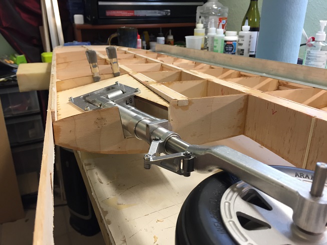
Progress, With the left wing framed up and the carbon fiber skins laied up I am starting to cut in the gear.
Skins are rough cut.


I am having issues with the left gear. The strut post is aluminum locked in the trunion, I need to send this back to Sierra.


First I cut the balsa sheeting away where the CF skin will go, and remove ribs 3 and 4 as they are not needed. I also remove rib 6.


Being the angle is wrong in the drawings and the cut parts the easiest way is to remove rib 6 as it is not needed and cut the gear plate short so it buts to rib 5 just below the mount.
This gives the correct angle.


This gives clearance for the gear doors and to cover the gear at the mount.

With the plate lowered it will need to be trimmed at the topside of the wing.
The gear will just clear the top skin.


The wheel fits fine so fare, about a 1/4" to play with.


Bottom plate will get trimmed at the LE.

All looks good so far as to the wheel fitting in the well.


Once I get both the same and make sure it is good I will add a new rib 3 and 4 to frame the wheel well.


TB
Skins are rough cut.
I am having issues with the left gear. The strut post is aluminum locked in the trunion, I need to send this back to Sierra.
First I cut the balsa sheeting away where the CF skin will go, and remove ribs 3 and 4 as they are not needed. I also remove rib 6.
Being the angle is wrong in the drawings and the cut parts the easiest way is to remove rib 6 as it is not needed and cut the gear plate short so it buts to rib 5 just below the mount.
This gives the correct angle.
This gives clearance for the gear doors and to cover the gear at the mount.
With the plate lowered it will need to be trimmed at the topside of the wing.
The gear will just clear the top skin.
The wheel fits fine so fare, about a 1/4" to play with.
Bottom plate will get trimmed at the LE.
All looks good so far as to the wheel fitting in the well.
Once I get both the same and make sure it is good I will add a new rib 3 and 4 to frame the wheel well.
TB
Last edited by TonyBuilder; 12-27-2015 at 09:29 AM.
12-28-2015, 12:27 PM
#113
progress
I cut the top skin. This is just a dry fit as I will not glue it in until both sides are set.
I had to send my left gear back to Sierra, once it comes back I can glue in the gear mounts.


The top skin will get a skin of 3/32 balsa over to flush out with the 1/8 skins.


The top skin gives strength to the wheel well as I have removed ribs 3,4, and 6.

TB
I cut the top skin. This is just a dry fit as I will not glue it in until both sides are set.
I had to send my left gear back to Sierra, once it comes back I can glue in the gear mounts.
The top skin will get a skin of 3/32 balsa over to flush out with the 1/8 skins.
The top skin gives strength to the wheel well as I have removed ribs 3,4, and 6.
TB
01-03-2016, 05:21 AM
#114
So I have on to the aileron fabrication.
The stock aileron is not scale at all and is your typical "RC" aileron with a beveled LE. To do the next best thing would be a pocket hinge and use Robart hinge pins, or a steel threw pin. This is easy to do and much better then the beveled hinge line.
The scale hinge line/ aileron is a Fries hinge. To do that you basically have to redesign the aileron. I have done this before so I know what to do.
The first step is to see what we got.
I made a template from my 3 view drawings.
You can see how much bigger the scale aileron is over the stock one.


I cut the portion of the pre-cut skin that ends at the ribs, my preferred way of building.
Then I framed it up as per plans. It is easier to just get started and make adjustments as you go, having something is better then not.
The white remaining portion will be solid balsa for the LE.


I cut in the G-10 TE and covered it with the cut out piece of balsa, this gets sanded to a taper.

TB
The stock aileron is not scale at all and is your typical "RC" aileron with a beveled LE. To do the next best thing would be a pocket hinge and use Robart hinge pins, or a steel threw pin. This is easy to do and much better then the beveled hinge line.
The scale hinge line/ aileron is a Fries hinge. To do that you basically have to redesign the aileron. I have done this before so I know what to do.
The first step is to see what we got.
I made a template from my 3 view drawings.
You can see how much bigger the scale aileron is over the stock one.
I cut the portion of the pre-cut skin that ends at the ribs, my preferred way of building.
Then I framed it up as per plans. It is easier to just get started and make adjustments as you go, having something is better then not.
The white remaining portion will be solid balsa for the LE.
I cut in the G-10 TE and covered it with the cut out piece of balsa, this gets sanded to a taper.
TB
01-03-2016, 06:39 AM
#115
The aileron hinges are made of 1/16" black G-10
I hade Chad laser cut them for me.
I am modifying them from the ones I did on my TFGS P-47. Just a bit more scale.
The difference is on the aileron side the hinge is at a 90 degree and the wing side is slanted.
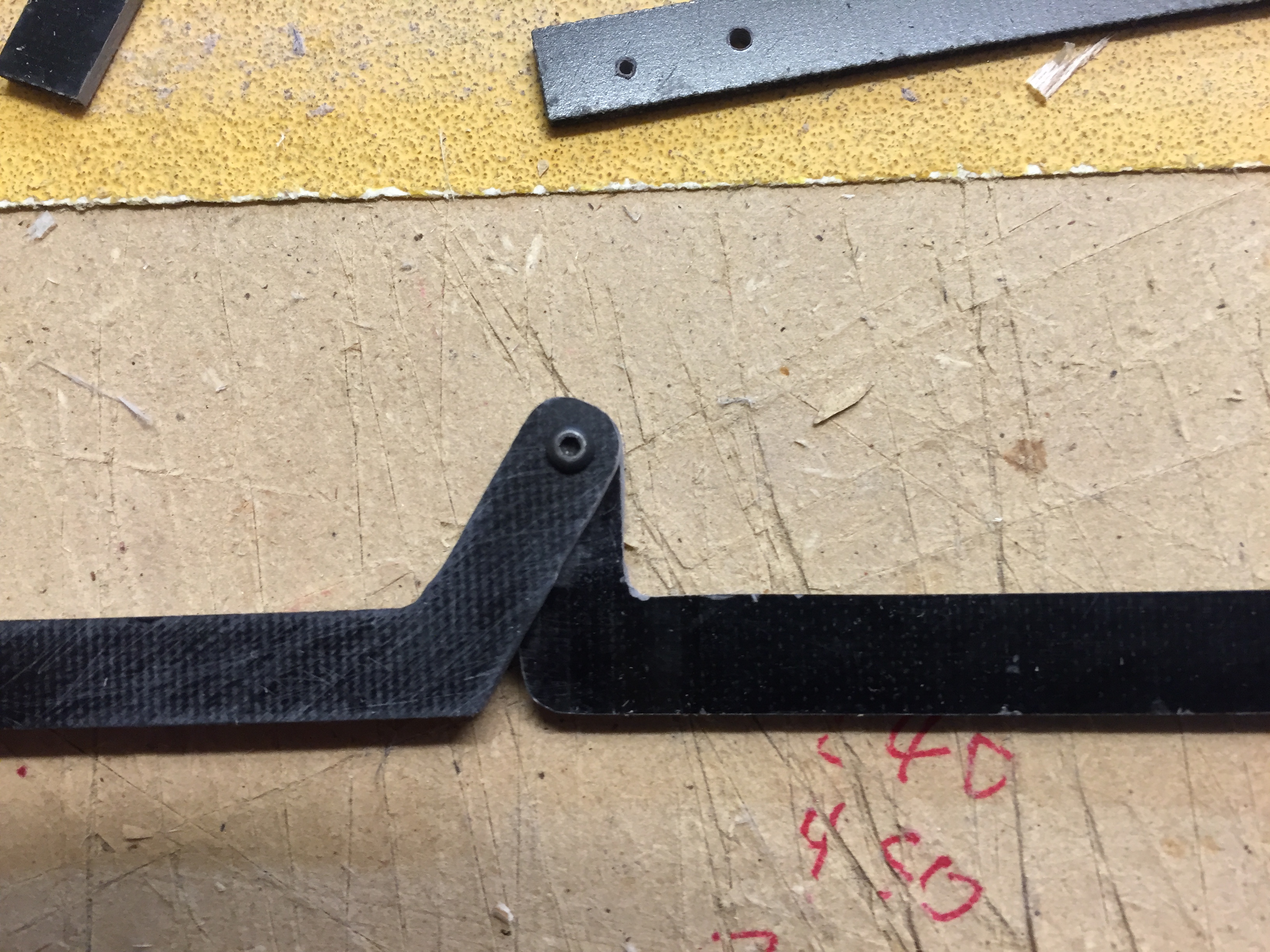
This allows for the hinge to cone strait down at the hinge line

The hinge is held with a #72 screw tap threaded into the G-10.


I did a mock up to check the correct location.


TB
I hade Chad laser cut them for me.
I am modifying them from the ones I did on my TFGS P-47. Just a bit more scale.
The difference is on the aileron side the hinge is at a 90 degree and the wing side is slanted.
This allows for the hinge to cone strait down at the hinge line
The hinge is held with a #72 screw tap threaded into the G-10.
I did a mock up to check the correct location.
TB
01-03-2016, 07:09 AM
#116
Progress
Next I need to install the hinge blocks. I am doing it a little different then before.
On the prototype I rounded the ends and installed them like Robart hinge pins. This required drilling a hole as you would for a hinge pin.
I don't like that as it is hard to get them all lined up and equal.
So I went with two square blocks sandwiching the hinge.
This is much easier as it sets the hinge square to the bottom. I added a piece of 3/32 balsa to get the correct depth of the hinge as it comes out of the bottom.
Then balsa block on each side.


Both sides are matched.


Blocks are in and ready for the top skin.


With the top skin glued in I faced the framing with 1/8 balsa. This helps hold it all together and keeps the aileron true and flat.
I cut a slot for the hinges.


Being the facing is broken at each hinge it no longer gives the rigidity to keep the aileron from warping so I added two strips of CF, one top and one bottom.
This has it true again.


TB
Next I need to install the hinge blocks. I am doing it a little different then before.
On the prototype I rounded the ends and installed them like Robart hinge pins. This required drilling a hole as you would for a hinge pin.
I don't like that as it is hard to get them all lined up and equal.
So I went with two square blocks sandwiching the hinge.
This is much easier as it sets the hinge square to the bottom. I added a piece of 3/32 balsa to get the correct depth of the hinge as it comes out of the bottom.
Then balsa block on each side.
Both sides are matched.
Blocks are in and ready for the top skin.
With the top skin glued in I faced the framing with 1/8 balsa. This helps hold it all together and keeps the aileron true and flat.
I cut a slot for the hinges.
Being the facing is broken at each hinge it no longer gives the rigidity to keep the aileron from warping so I added two strips of CF, one top and one bottom.
This has it true again.
TB
01-03-2016, 01:39 PM
#117
Progress
With the top and bottom sheeting on and the test fitting of the hinges I will add the LE


LE is installed and being shaped.


I installed the balsa LE in pieces to create the gap for the hinges, much easier this way.


You can see how much bigger the scale aileron is over the RC aileron.


Hinges fit good and the depth is perfect.


This looks good and next I will sand the profile in the LE.


Control horn will get trimmed later.

More testing the hinge installation.


So far so good.


TB
With the top and bottom sheeting on and the test fitting of the hinges I will add the LE
LE is installed and being shaped.
I installed the balsa LE in pieces to create the gap for the hinges, much easier this way.
You can see how much bigger the scale aileron is over the RC aileron.
Hinges fit good and the depth is perfect.
This looks good and next I will sand the profile in the LE.
Control horn will get trimmed later.
More testing the hinge installation.
So far so good.
TB
01-03-2016, 02:08 PM
#118
Progress
I sanded the LE profile, I have a suspicion that I over sanded the tip.")


I am cutting in the w aileron.


Rough cutting is done.


CF TE at the top of the wing at the aileron is in.


Yep...I over sanded the tip. I will cut it off, glue in some block and sand to fit.

TB
I sanded the LE profile, I have a suspicion that I over sanded the tip.
I am cutting in the w aileron.
Rough cutting is done.
CF TE at the top of the wing at the aileron is in.
Yep...I over sanded the tip. I will cut it off, glue in some block and sand to fit.
TB
01-04-2016, 05:28 AM
#121

Join Date: Apr 2005
Location: Southbury CT
Posts: 286
Likes: 0
Received 0 Likes
on
0 Posts
Tonybuilder,
I have only built a couple of kits so please bare with me if possible. I have a couple questions for you. The jig that you fabricated back in August for the fuse, was that fabricated on your own or did the plans have an example on them that you copied? also, you have what looks like a clamp holding up the fuse to the jig that you made, what kind of a clamp is that?
I have only built a couple of kits so please bare with me if possible. I have a couple questions for you. The jig that you fabricated back in August for the fuse, was that fabricated on your own or did the plans have an example on them that you copied? also, you have what looks like a clamp holding up the fuse to the jig that you made, what kind of a clamp is that?
01-06-2016, 06:22 AM
#122
Progress
I am installing the hinges into the wing. I am doing this a little different then before. This allows me to fine tune as I install.
I am making the blocks out of 4 pieces sandwiching the square hinge arm in between creating a channel for the hinge.


This then gets cut into the wing just behind the TE blocking and fascia.


Then I glue them in one at a time with epoxy.


Once in a prep for sanding. It has a two step, as the portion up agents the TE is flush with the top skin and the portion behind is flush with the ribbing.


Once sanded then I can check that the top skin fits.
Movement is checked.


All looks good and I wont do final sanding until the bottom skin and pocket are installed.


I am going to install the servo tray next so I cut in the path for the push rod.
A HD 4-40 clevis is going to be used with 4-40 threaded rod.


Fine tuning will come once the hinges are glued in, but not until the wing bottom skin is in and the wing tips.


TB
I am installing the hinges into the wing. I am doing this a little different then before. This allows me to fine tune as I install.
I am making the blocks out of 4 pieces sandwiching the square hinge arm in between creating a channel for the hinge.
This then gets cut into the wing just behind the TE blocking and fascia.
Then I glue them in one at a time with epoxy.
Once in a prep for sanding. It has a two step, as the portion up agents the TE is flush with the top skin and the portion behind is flush with the ribbing.
Once sanded then I can check that the top skin fits.
Movement is checked.
All looks good and I wont do final sanding until the bottom skin and pocket are installed.
I am going to install the servo tray next so I cut in the path for the push rod.
A HD 4-40 clevis is going to be used with 4-40 threaded rod.
Fine tuning will come once the hinges are glued in, but not until the wing bottom skin is in and the wing tips.
TB
Last edited by TonyBuilder; 01-06-2016 at 06:34 AM.
03-04-2016, 02:19 PM
#124

My Feedback: (6)
Hay T/B
Glad it was nothing serious
Will your new shop be bigger ? back when we built our current home I built my shop on the back of the garage so its 12 X 26 and I thought it was huge but after getting the benches built and some tools mounted to the walls and a rolling box bench in the middle, it some how got a little small real fast.
But have fun in your new digs
Cheers Bob T
P/S it also has A/C and Heat
03-04-2016, 04:57 PM
#125
Hay T/B
Glad it was nothing serious
Will your new shop be bigger ? back when we built our current home I built my shop on the back of the garage so its 12 X 26 and I thought it was huge but after getting the benches built and some tools mounted to the walls and a rolling box bench in the middle, it some how got a little small real fast.
But have fun in your new digs
Cheers Bob T
P/S it also has A/C and Heat
Glad it was nothing serious
Will your new shop be bigger ? back when we built our current home I built my shop on the back of the garage so its 12 X 26 and I thought it was huge but after getting the benches built and some tools mounted to the walls and a rolling box bench in the middle, it some how got a little small real fast.
But have fun in your new digs
Cheers Bob T
P/S it also has A/C and Heat
and a full wood shop in the garage so I'm hopping to get my room setup this weekend.
TB