


Sig Hog Bipe - Electrified!
 10-20-2016 | 07:51 PM
#1
Thread Starter
Banned
Hi Guys,
It has literally been years that I got to the building board. Life is busy - (so what's new?) -and sometimes life happens.
I am also a vivid cyclist and this last seven years - I dedicated most of my spare time, to cycling. But it's not all just for fun - I did this year my seventh ride for MS. The MS150 miles in New Mexico - All for a good cause.
Anyway - I am finally trying to see how I can do both - flying ('cause building too) and cycling - A few years back at my local flying club, I told one of my co-flyers (after he ask why they do only see me so rarely) my story and he said "Well son, you know you can only have one god".....OK. I guess that stuck with me for a few years and I devoted my time to cycling. But watch me..!
LOL
OK. Enough of that. Back to the Hog: I probably bought this kit 8-9 years back and it was sitting with about 7 others in my garage, I decided on the hog to build first. Why? - I just love biplanes - don't know why - they just looks cool and I never flown one, I do have a finished Skybolt (electrified) too - never flown, I'll get to that, once I get back more to flying and are more confident,
Anyway - I read the previous forum (http://www.rcuniverse.com/forum/kit-...ipe-build.html) on the Hog Bipe and found a few very interesting points and ideas that I will try to accommodate in my build. First off, let me please apologize if I use some of your ideas and do not thank, or quote you properly for using it. Here we go "THANK YOU" - you will know who you are if you see your idea(s) here.
But these are my plans for the Bog, so for:
1) Make new enlarged plate for landing gear (1/4" Plywood) attachment to fuse. I have also decide to use Carbon Fiber landing gear, that I already had and it looks and fit perfectly, It's actually about 1" taller, but the rest of the dimensions are exactly the same (or very close to it - more on this later). i will also use 1/4-20 plastic bolts to mount the landing gear to the fuse. Just in case of a hard landing, to take damage on the bolts, rather on the plane. I don't know if this is a good idea - but I am willing to try it. Talking about CF - I have enforced F3 with a piece of CF where the wing dowels comes in. I sandwiched the CF in between F3 and F3B (I'll call it F3CF) See the pictures of that below.
I have decided the move the tail servos to the back. I prefer longer servo leads, rather than longer push-rods. I am not that familiar with pull-pull setups yet. So I already created the mounts in the read of each fuse side.
I'll show some pics of this too, once the glue is cured.
2) I am planning on carving the headset from Balsa rather than using the plastic. I just don't like that plastic.
3) Before I will start building the bottom wings - I'll check to see if the lengths of the bottom pair are the same. Some place I read that someone claimed that his left and right bottom wings were not the same length on the plan. Well - I'll just check mine when I get to that.
4) I am planing on using the dual servo setup, included with the kit. I first decided on 4 servos, but then decided against it for numerous reasons. Cost, how to manage the servo wire, etc. I also read someplace (sorry guys, if I do not quote you all properly - It'll take me another year just to go find all your names and links to your entries, if I have to quote you all)- NOT to use the supplied, small screws for the servo mounting plates. Instead use #2 9/16 fully threaded one's. I'll do this to mount the servos. I already have the two servos I want to use in the wings: Savox SC-0251's (https://www.amazon.com/Savox-SC-0251...=Savox+SC-0251)
5) Use 1/4" Plywood inside wings for strut-mounts - not the supplied 1/8" ?? _ I read this here: (http://www.rcuniverse.com/forum/kit-...ml#post6764089) but are not sure I totally understand, Does he refer to the portions that the struts connect to or the inside of the wing? Once I get to the wings - maybe I'll understand that bettter.
6) Roll paper for servo wire channels in wings. Figure out how to easily connect these servos (maybe 9-pin plugs??) - I do have male/female 9-pin serial (RS232 ??? - I think) connectors, that I planning to accommodate as a connector for the two servos - more on this later too.
7) Cabanes: blind nuts (one drilled out) on both sides on mounting struts for stiffness - Well, I tried to drill out on blind (/T) nut, and I totally mess it up. I could not get this to work. And my local hardware store does not have this size at all so I can buy a few extra and play with it. I noticed that TowerHobbies have some. Anyway - I messed up on my fuse- I was not thinking, ok. I first mounted and glued a T-nut on the outside and after it was cured, I tried to glue the inside on and use the bolt to draw it in place - BAD IDEA....the outside one must not have been properly in place, because when I turned the screw, it eat it's way deeper and deeper into the wood. Well, as I said - I messed this idea totally up. So to strengthen the outside of the cabane mounts, I have decided to use 1.5mm Carbon Fiber strips, about 1" wide with holes drilled so the bolts can rest on the CF. I'll show pictures of this, once I get to that too. For this minimum more weight, I think the CF will give very strong support for the wings on the fuse. Bad idea???
I did fit the cabanes into the holes before gluing on the sides - to see if the holes line up. They line up properly and I can even get all four screws through.
8) I have decided to re-enforce the bottom wing with Keflar and Epoxy to make it stronger. Also around the strut mountings, maybe?
9) I have started planing the battery tray inside the fuse, with a bottom access door, between the nose and the landing gear. This is still a work in progress, but I have a pretty good idea of what I am going to do. I'll share some of these pics once the glue is dry.
10) I read about someone enlarged the rudder by 3/4 inch (by glued 1/4 x 3/4 stock to leading edge of rudder). Then in another thread, I read that someone advised against it - so I am a little in between here - and do not know what to do.
If I will do that, I will probably have to also increased opening in the elevator to allow more rudder throw.
13) Finally - I hate the open nose of this plane, I can understand the need for it (really?) for a non-electric build. but really?? SO I am planning to build a balsa nose cowl - even if it's just the top part - I'll sleep on that some.
OK. so here are a few pics I took yesterday. This is not much, but at least I started to take some pics. I'll take more tomorrow and share what I have once the glue is dry (and I got off from work!).
Last edited by bert269; 10-22-2016 at 02:12 PM.

The following users liked this post:
knuckleball (09-09-2021)
10-21-2016 | 06:11 AM
#2
Thread Starter
Banned
I got another few thoughts this morning - (wow - standing in the shower can sometimes really bring up bright ideas!)
I will be cutting a piece of CF to be the same size as the stut-mounts in the wings and compare the weight. I'm sure CF will be lighter than if I have to use 1/4" plywood (according to the previous suggestion to use 1/4" instead of the supplied 1/8") That likely will be soaking up the CA - I know for a fact it will be much stronger.
And since I am planning on some black covering, I think the black CF will not stand out too much on the wings.
Also - I am thinking of fabricating my servo pushrods from CF-rods. I have a bunch of these and I can just as well use it. It's certainly strong and light enough.
Just some more thoughts - I will keep updating this as I go along.
10-22-2016 | 02:46 AM
#3

Great start on a build thread. I just bought the Sig Hog Bipe kit and it's going to be electric too, not quite sure when I'll start on it though.
One question on the "1/4-20 plastic bolts to mount the landing gear to the fuse". I tried that on a 40 sized plane and it still kept taking out the plywood gear mount instead of breaking the bolts, so anyone's thoughts on this would be helpful.
bert269, I be tagging along!
One question on the "1/4-20 plastic bolts to mount the landing gear to the fuse". I tried that on a 40 sized plane and it still kept taking out the plywood gear mount instead of breaking the bolts, so anyone's thoughts on this would be helpful.
bert269, I be tagging along!
10-22-2016 | 02:25 PM
#5
Thread Starter
Banned
Here are some of the pics I took yesterday as I was progressing on the fuse.
I will explain what is happening inside the fuse.
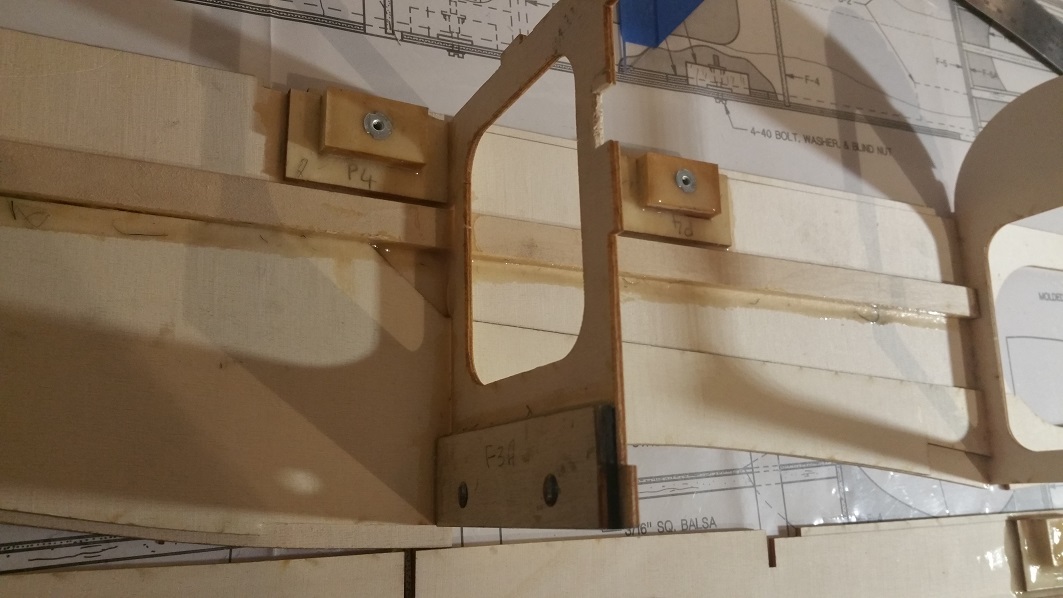
Since I'm electrifying and need to find te correct CG I've decided to use as much of the fuse to mount the batteries on, as I can. Therefore, I epoxied a piece of 1/2"x 1/4" basswood on each side. This will act as the "rail-hanger" for the actual battery mount I'll be creating. Since the battery-hatch will be in the bottom -front (just before the landing gear) - I decided to let the batteries hang, rather than "Sit" on the battery-tray. If you look carefully, you can see the basswood "rails" in these pictures.
If you look carefully, you will see tha 1/8" gap between the "rail" and the bottom of the cabane mounts, - this is where I'll place the actual battery-tray.
In the second picture, you can see the result form the CF-enforced wing mount (or whatever it's called.

I will explain what is happening inside the fuse.
Since I'm electrifying and need to find te correct CG I've decided to use as much of the fuse to mount the batteries on, as I can. Therefore, I epoxied a piece of 1/2"x 1/4" basswood on each side. This will act as the "rail-hanger" for the actual battery mount I'll be creating. Since the battery-hatch will be in the bottom -front (just before the landing gear) - I decided to let the batteries hang, rather than "Sit" on the battery-tray. If you look carefully, you can see the basswood "rails" in these pictures.
If you look carefully, you will see tha 1/8" gap between the "rail" and the bottom of the cabane mounts, - this is where I'll place the actual battery-tray.
In the second picture, you can see the result form the CF-enforced wing mount (or whatever it's called.
10-22-2016 | 02:29 PM
#6
Thread Starter
Banned
Yesterday, I also started gluing the two sides of the fuse, together. Here you can see my fire-box and a DVD case, weighing it down a little. I must say, I think the result came out pretty well.

10-22-2016 | 02:34 PM
#7
Thread Starter
Banned
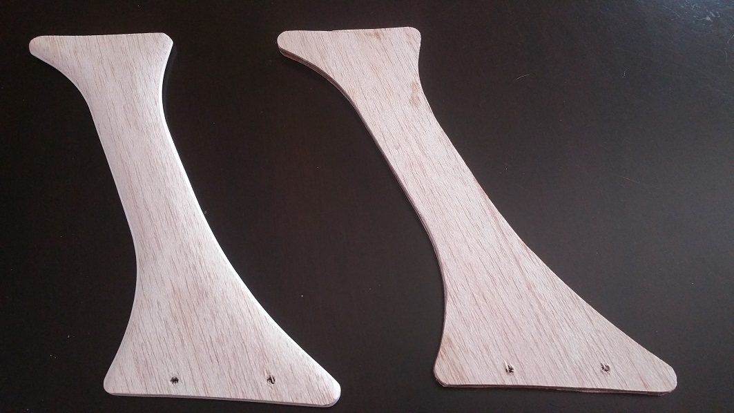
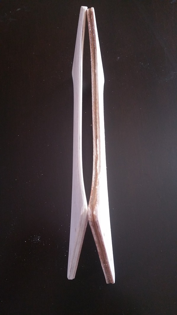
While I was doing the long process of getting the fuse into shape, I started with the wing-struts, this morning.
I used the supplied struts (which is actully 3/32"!!!) and epoxied a 1/6" balsa on each side.
Here you can see (on the left) the one that I started sanding, to give it some airfoil.
I used the supplied struts (which is actully 3/32"!!!) and epoxied a 1/6" balsa on each side.
Here you can see (on the left) the one that I started sanding, to give it some airfoil.
10-25-2016 | 06:35 PM
#8
Thread Starter
Banned
The fuse is getting there.
I glued the two sides all the way together. Finished the servo mounts in the back and also temporarily added the tail-wheel to see if it would work.
Further, I open the battery hatch and are working on the closing mechanism - I'll attach some of these pictures later after the glue has cured.


I glued the two sides all the way together. Finished the servo mounts in the back and also temporarily added the tail-wheel to see if it would work.
Further, I open the battery hatch and are working on the closing mechanism - I'll attach some of these pictures later after the glue has cured.
10-25-2016 | 06:50 PM
#9
Thread Starter
Banned
OK. besides for putting on a latch for the battery hatch, I think I have it covered. I glued four pieces of 1/8" (or whatever the thickness is of the ply the fuse sides are from - I think it's actually 3/32) plywood, an all four sides, to keep the hatch-door from recessing too deep (picture 1).

The hatch-door itself has two hooks that I made from push-pins, cut and bent into the correct shape (pic 2).

I actually bent a piece perpendicular to the rest of the pin that goes vertically into the hatch-door. All glued in place, secured with another small piece of carved-out plywood, to conform to the shape of the pushpin (pic 3). As soon as this is dry tomorrow, I'll sand the plywood smooth, so it does not extend past the edge of the hatch-door.

Yeah, I know the one is bigger than the other, but my attempts to carve out the shape of the left push-pin keeps on destroying the plywood - so I decided to go a little bigger. My third attempt actually worked (but now the left is bigger than the right. I'll just ensure my servo wires run down the right of the fuselage to accommodate the offset in weight.(LOL)
Since this hatch will not bare any weight, I think the push-pins should hold it in place. I already have the latch- I just need to attach it to the fuse and ensure it's working as it should.
The hatch-door itself has two hooks that I made from push-pins, cut and bent into the correct shape (pic 2).
I actually bent a piece perpendicular to the rest of the pin that goes vertically into the hatch-door. All glued in place, secured with another small piece of carved-out plywood, to conform to the shape of the pushpin (pic 3). As soon as this is dry tomorrow, I'll sand the plywood smooth, so it does not extend past the edge of the hatch-door.
Yeah, I know the one is bigger than the other, but my attempts to carve out the shape of the left push-pin keeps on destroying the plywood - so I decided to go a little bigger. My third attempt actually worked (but now the left is bigger than the right. I'll just ensure my servo wires run down the right of the fuselage to accommodate the offset in weight.(LOL)
Since this hatch will not bare any weight, I think the push-pins should hold it in place. I already have the latch- I just need to attach it to the fuse and ensure it's working as it should.
Last edited by bert269; 10-25-2016 at 06:56 PM.
 Most of my building is done with CA and epoxy, what glues are you using?
10-27-2016 | 05:05 AM
Most of my building is done with CA and epoxy, what glues are you using?
10-27-2016 | 05:05 AM
#11
Thread Starter
Banned
Thank you!
Yep - CA and epoxy here too (although I think the color of the epoxy is a little 'off'...LOL).
Well, The plan did not call for the enforcement in the wing mount (where the dowels enter the fuse) - I decided to add that by layering a 1.5mm Carbon Fiber plate in between the plywood.
I finished the battery hatch and door. See attachment.

Last evening I also added two CF strips, one on each side of the fuse, where the bolts goes in to hold the cabanes. I run into a problem here earlier (as I mentioned in my first post, #7) - so I decided to make sure the cabanes is not going anywhere. I'll post pictures later today when I get home.
I am almost about done with my fuse - I am not going to do the rest until after I have all the wings build to ensure I have the correct mounting positions for my battery. Therefore I will leave the Fuse Top Front (FTF) and F2, F4 until I have a better feel for the correct CG.
The only other big thing for the fuse I have to do is build the balsa nose cowl - but first I need to stop at the LHS to pick up a piece of 1" x 4" x 4" balsa (at least) to carve the cowl from. I do not like the open top of the nose and since it's electric - I do not need that. The bottom opening is fine - I'll leave that.
I am a little baffled by step 13 in the fuse build. If you look carefully at the plan, it looks like the aluminum cabanes goes in between two ply layers P6 and P8 - (although P7 and P8 are not marked, but according to the plan it looks like it P6 & P8). Then you put a T-nut (blind-nut) in from the bottom side, but the sharp edges of the t-nut (that goes into the wood) would hit the aluminum cabane strut!!
I'll did some research in the other thread for the Hog Bipe Build, but could not find anything regarding this.....maybe I'll cut off a portion of the sharp points, so that it can only go into one the the plywood plates.
Yep - CA and epoxy here too (although I think the color of the epoxy is a little 'off'...LOL).
Well, The plan did not call for the enforcement in the wing mount (where the dowels enter the fuse) - I decided to add that by layering a 1.5mm Carbon Fiber plate in between the plywood.
I finished the battery hatch and door. See attachment.
Last evening I also added two CF strips, one on each side of the fuse, where the bolts goes in to hold the cabanes. I run into a problem here earlier (as I mentioned in my first post, #7) - so I decided to make sure the cabanes is not going anywhere. I'll post pictures later today when I get home.
I am almost about done with my fuse - I am not going to do the rest until after I have all the wings build to ensure I have the correct mounting positions for my battery. Therefore I will leave the Fuse Top Front (FTF) and F2, F4 until I have a better feel for the correct CG.
The only other big thing for the fuse I have to do is build the balsa nose cowl - but first I need to stop at the LHS to pick up a piece of 1" x 4" x 4" balsa (at least) to carve the cowl from. I do not like the open top of the nose and since it's electric - I do not need that. The bottom opening is fine - I'll leave that.
I am a little baffled by step 13 in the fuse build. If you look carefully at the plan, it looks like the aluminum cabanes goes in between two ply layers P6 and P8 - (although P7 and P8 are not marked, but according to the plan it looks like it P6 & P8). Then you put a T-nut (blind-nut) in from the bottom side, but the sharp edges of the t-nut (that goes into the wood) would hit the aluminum cabane strut!!
I'll did some research in the other thread for the Hog Bipe Build, but could not find anything regarding this.....maybe I'll cut off a portion of the sharp points, so that it can only go into one the the plywood plates.
10-27-2016 | 02:20 PM
#12
...
I am a little baffled by step 13 in the fuse build. If you look carefully at the plan, it looks like the aluminum cabanes goes in between two ply layers P6 and P8 - (although P7 and P8 are not marked, but according to the plan it looks like it P6 & P8). Then you put a T-nut (blind-nut) in from the bottom side, but the sharp edges of the t-nut (that goes into the wood) would hit the aluminum cabane strut!!
I'll did some research in the other thread for the Hog Bipe Build, but could not find anything regarding this.....maybe I'll cut off a portion of the sharp points, so that it can only go into one the the plywood plates.
You say the kit was a few years old. I just bought mine two weeks ago from Tower Hobbies so here are two pictures from the drawing showing the side and front views of the cabane, plywood and blind nut stackup in case things have been updated. Also you can get the latest PDF manual at http://www.sigmfg.com/cgi-bin/dpsmar...osF.html?E+Sig
Do you see any differences?
10-28-2016 | 06:21 AM
#13
Thread Starter
Banned
Thanks for the update and the confirmation with the pictures. Yep, it's the same as mine.
I did start the Cabanes last evening and it is correct: The sharp points of the blind-nuts needs to be trimmed a little as they stick though the bottom plate (P8) and does obstruct the cabanes to settle on the plate - not a big deal. Just something to look out for.
Here are the rest of the pics I took yesterday. AS promised the complete fuse(for now, without the front) until I can get a better understanding of the CG.
I should receive the Balsa block (2"x4"x12") on Monday, that I ordered. Then I will do the nose cowl.

Here's a close-up of the CF Cabane-nuts support, that I glued to the sides. No fear of the nuts going though the sides anymore.

I'm done with the Fin too, the only thing that left is the fin and sanding. I'll start with that this weekend.

I did start the Cabanes last evening and it is correct: The sharp points of the blind-nuts needs to be trimmed a little as they stick though the bottom plate (P8) and does obstruct the cabanes to settle on the plate - not a big deal. Just something to look out for.
Here are the rest of the pics I took yesterday. AS promised the complete fuse(for now, without the front) until I can get a better understanding of the CG.
I should receive the Balsa block (2"x4"x12") on Monday, that I ordered. Then I will do the nose cowl.
Here's a close-up of the CF Cabane-nuts support, that I glued to the sides. No fear of the nuts going though the sides anymore.
I'm done with the Fin too, the only thing that left is the fin and sanding. I'll start with that this weekend.
11-07-2016 | 07:09 AM
#14
Thread Starter
Banned
I got a few things done this past weekend. I finished most of the back feathers (stab, fin and rudder). I decided, since the stabilizer is 3/8" thick and the fin/rudder only 1/4", to add 1/6" balsa on both sides of the rudder. This mean I had to order another piece for the rudder (that is not 1/4" but 3/8"). Here is the result from my attempt. It may add a little weight, but I cannot see why the stab and rudder two were not the same thickness from the start.
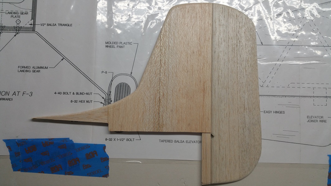
All I have to do is add the hinges and the tail-wheel hook (if I am going to do that and not let the wheel turn freely - have not decided what to do here, yet). I am still working on the elevators, to get them equal size and shape.
In the mean time, I have also started the top wing. This is the progress of that:

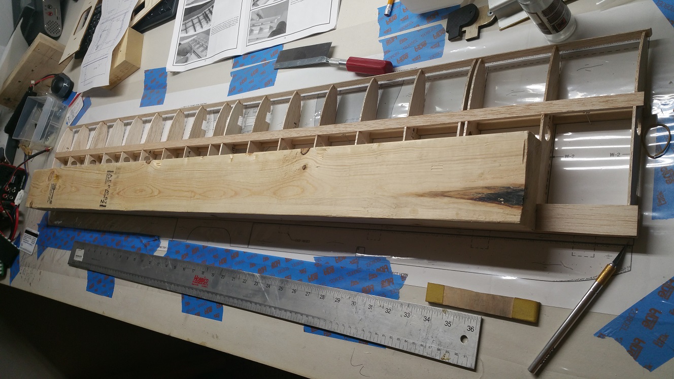
Instead of using the supplied two 1/4"x1/2"x24" balsa sticks for the bottom spar, I used a 48" basswood piece from my own supply. I just think it would be stronger for the needed support and do not think the weight difference will be that much, compared to the added strength. As you can see in the font of the above picture (and below), I also strengthen the P2 mounts with a equivalent cut-out piece of Carbon Fiber.
 After I glued both pieces together I realized I should have instead glued the CF onto the same side as the blind-nut or ultimately, to get the most strength would be to sandwich the plywood between two CF plates - but I was not not that enthusiastic.
Below you can see the progress of the top wing. The first pic was to hold it down before gluing the top sheeting in place and the second on was after the top sheeting was in place, I discovered a little upward twist at both tips - which I am trying to straighten out (second picture) with some weight. It's not a lot, (about 1/6") and it all happen after the top sheeting was glued in place. I recall although the edge of the sheet was straight, it had a weird twist in the sheet. So I soaked the whole wing with spayed on water and let it dry. Hopefully it will cure. The last resort to fix this, will be when I place the bottom sheeting on the make sure everything is straight. But it still is strange, since my work board is totally flat!
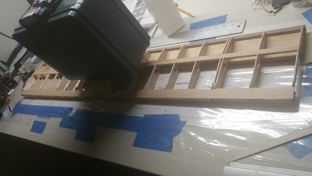
More to come as I progress with the top wing.
All I have to do is add the hinges and the tail-wheel hook (if I am going to do that and not let the wheel turn freely - have not decided what to do here, yet). I am still working on the elevators, to get them equal size and shape.
In the mean time, I have also started the top wing. This is the progress of that:
Instead of using the supplied two 1/4"x1/2"x24" balsa sticks for the bottom spar, I used a 48" basswood piece from my own supply. I just think it would be stronger for the needed support and do not think the weight difference will be that much, compared to the added strength. As you can see in the font of the above picture (and below), I also strengthen the P2 mounts with a equivalent cut-out piece of Carbon Fiber.
Below you can see the progress of the top wing. The first pic was to hold it down before gluing the top sheeting in place and the second on was after the top sheeting was in place, I discovered a little upward twist at both tips - which I am trying to straighten out (second picture) with some weight. It's not a lot, (about 1/6") and it all happen after the top sheeting was glued in place. I recall although the edge of the sheet was straight, it had a weird twist in the sheet. So I soaked the whole wing with spayed on water and let it dry. Hopefully it will cure. The last resort to fix this, will be when I place the bottom sheeting on the make sure everything is straight. But it still is strange, since my work board is totally flat!
More to come as I progress with the top wing.
11-10-2016 | 05:22 AM
#15
Thread Starter
Banned
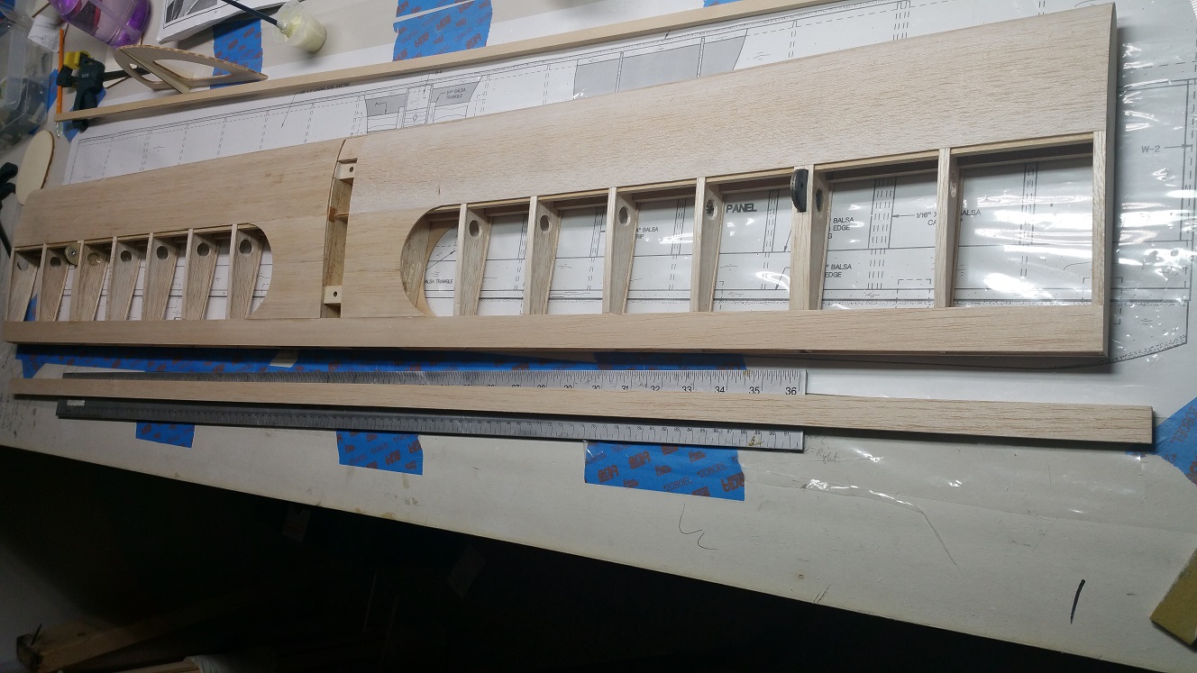
I am getting there with the Top wing. All the sheeting and capstrips are done. Only things left are the trailing edge, wingtips and ailerons. In the second picture you can see a close-up of the P2-CF enforced mounted on the wing. If everything works out well, I should be able to complete the top wing this weekend. More to come.

I did order the fiberglass nose cowl from Fiberglass Specialties (SK-26 : http://www.fiberglassspecialtiesinc.com/catalog.htm) and it should be arriving today. I'll include some pictures of that too later.
I did order the fiberglass nose cowl from Fiberglass Specialties (SK-26 : http://www.fiberglassspecialtiesinc.com/catalog.htm) and it should be arriving today. I'll include some pictures of that too later.
11-23-2016 | 03:12 PM
#16
I guess not as many people build like they used to. I have two builds going now a RC and a CL stunt plane before I start the Hog Bipe but just wanted to let you know I'm really enjoying the thread and your design ideas in the meantime. :-)


