


New: Pull-Pull System - Need Help!!!
 01-12-2019 | 01:20 PM
#1

Thread Starter

Joined: Aug 2002
Posts: 654
Likes: 0
Received 0 Likes
on
0 Posts
From: Massapequa Park, NY
Hi Guys,
I am an old time builder from way back. However after 45 yrs. + of building and flying experience I have just never have gotten around to putting together a Pull-Pull Cable System. I am working on installing one now on the Elevator in a P-51-Mustang. So all has been going well, except I am at the point where all is connected up and the cables are setup & the tension is fairly firm. I have the servo centered and have tried to test the control system. However, when I check the tension of the control service when the servo is centered and at rest, there is a lot of sloppy play in the Elevator. I try to flex it a bit up & down. I feel it is very sloppy, way too sloppy nothing like my old tried & true controlrod set-ups. I truly believe if this was flown with the current setup, there is 95% chance there would be some serous flutter. All I can imagine is it fluttering and getting worse by the second, until the tail actually explodes into pieces and crashes due to the Fluttering issue.
I have tried to adjust the tension of the cables to a very tight & firm cable setup, to a set up with tension with some slight amount of slack in it. I have tried several types of tension setups and all producing the same result, sloppiness in the Elevator which I really believe would be a “Big Time Flutter Issue”. I even checked all of the other aircraft that I own (13 of them) that are currently setup to fly with straight rods. All have no issues of being sloppy, none at all using the old tried and true straight rod approach….
The last thing I will add is the cable run description:
Looking inside the plane, with the wing saddles facing upward.
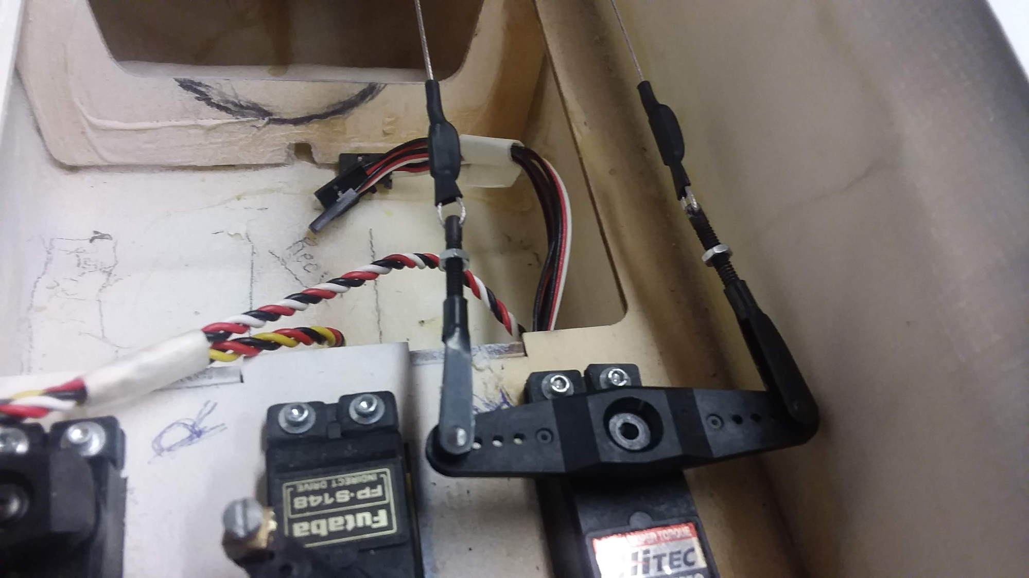
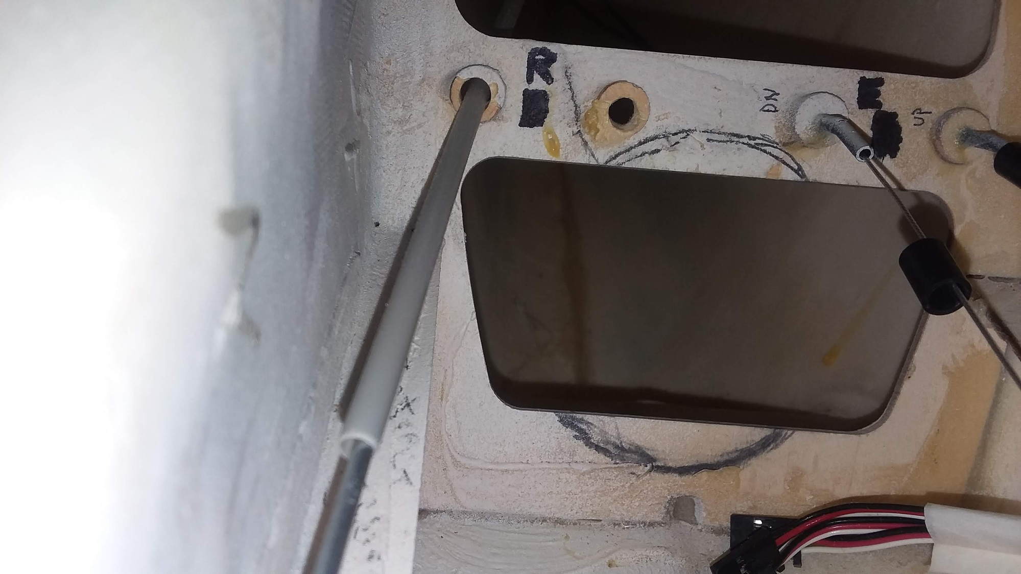
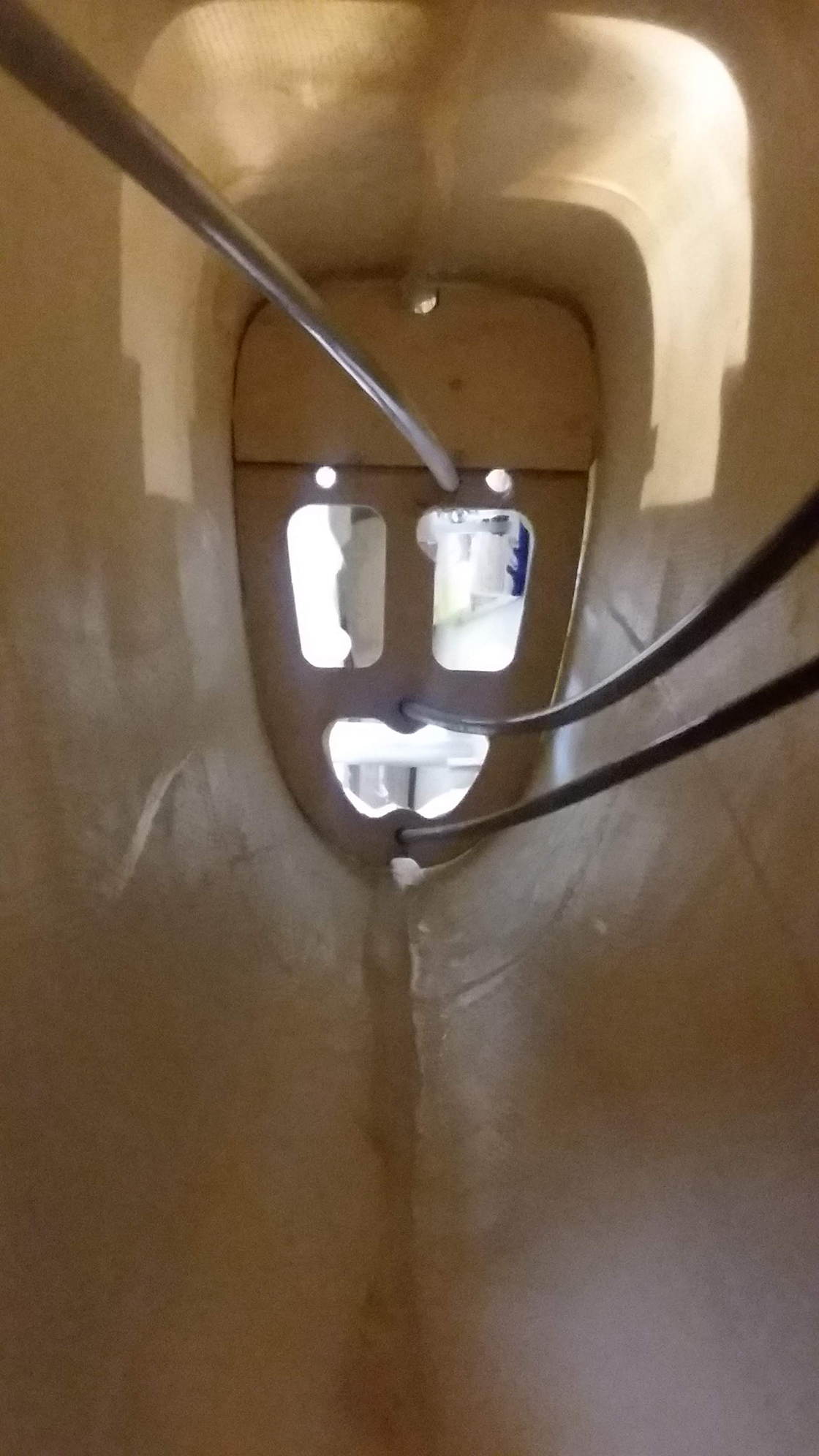
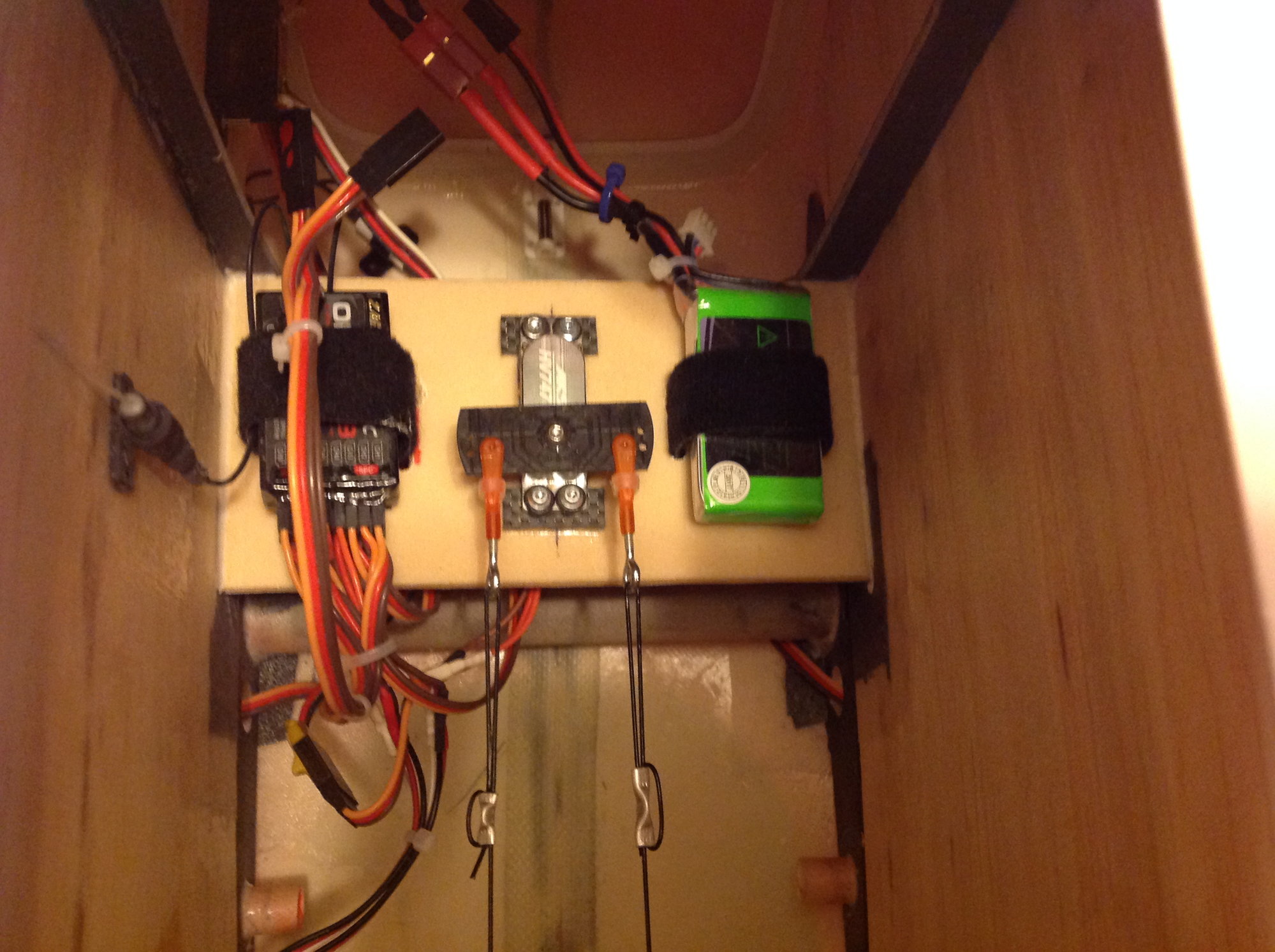
From the Servo: There’s approx. 4 inches of a straight cable run in where the cable then enters into a plastic guide tube. There is a slight 10 deg. downward bend in the plastic tube guide as it passes thru a former. Then there is a straight run of about 16 inches at approx. a 5 deg. downward direction. Then it passes thru the former and is pretty much a straight run for about another 4 inches and it connects to the U-shaped wire to which is setup into the two Elevator halves. All of the connections appear to be tight and no slippage.
What I did find is that when you are in Neutral position and the Elevator Halves are Centered, if you reach into the back of the fuse where the hatch is open on the bottom of the fuse below the tail section and grab the cable, you can push down or Pull up on the cable approx. 1 inch in either direction, the cable seems to have some play and stretch a bit. All of the crimps and the clevises are tight, it almost seems like as if the cable itself is stretching a bit in either direction like a rubber band. The System I am using is from Dubro. The Dubro Pull-Pull System 4-40 - (Tower Stock# LXD859 • Manufacturer Stock# 518).
Please let me know your thought’s or comments on this set up.
Thanks a Bunch
Ed

I am an old time builder from way back. However after 45 yrs. + of building and flying experience I have just never have gotten around to putting together a Pull-Pull Cable System. I am working on installing one now on the Elevator in a P-51-Mustang. So all has been going well, except I am at the point where all is connected up and the cables are setup & the tension is fairly firm. I have the servo centered and have tried to test the control system. However, when I check the tension of the control service when the servo is centered and at rest, there is a lot of sloppy play in the Elevator. I try to flex it a bit up & down. I feel it is very sloppy, way too sloppy nothing like my old tried & true controlrod set-ups. I truly believe if this was flown with the current setup, there is 95% chance there would be some serous flutter. All I can imagine is it fluttering and getting worse by the second, until the tail actually explodes into pieces and crashes due to the Fluttering issue.
I have tried to adjust the tension of the cables to a very tight & firm cable setup, to a set up with tension with some slight amount of slack in it. I have tried several types of tension setups and all producing the same result, sloppiness in the Elevator which I really believe would be a “Big Time Flutter Issue”. I even checked all of the other aircraft that I own (13 of them) that are currently setup to fly with straight rods. All have no issues of being sloppy, none at all using the old tried and true straight rod approach….
The last thing I will add is the cable run description:
Looking inside the plane, with the wing saddles facing upward.
From the Servo: There’s approx. 4 inches of a straight cable run in where the cable then enters into a plastic guide tube. There is a slight 10 deg. downward bend in the plastic tube guide as it passes thru a former. Then there is a straight run of about 16 inches at approx. a 5 deg. downward direction. Then it passes thru the former and is pretty much a straight run for about another 4 inches and it connects to the U-shaped wire to which is setup into the two Elevator halves. All of the connections appear to be tight and no slippage.
What I did find is that when you are in Neutral position and the Elevator Halves are Centered, if you reach into the back of the fuse where the hatch is open on the bottom of the fuse below the tail section and grab the cable, you can push down or Pull up on the cable approx. 1 inch in either direction, the cable seems to have some play and stretch a bit. All of the crimps and the clevises are tight, it almost seems like as if the cable itself is stretching a bit in either direction like a rubber band. The System I am using is from Dubro. The Dubro Pull-Pull System 4-40 - (Tower Stock# LXD859 • Manufacturer Stock# 518).
Please let me know your thought’s or comments on this set up.
Thanks a Bunch
Ed
Last edited by Electriceddie; 01-12-2019 at 01:38 PM.
 01-12-2019 | 02:13 PM
#2


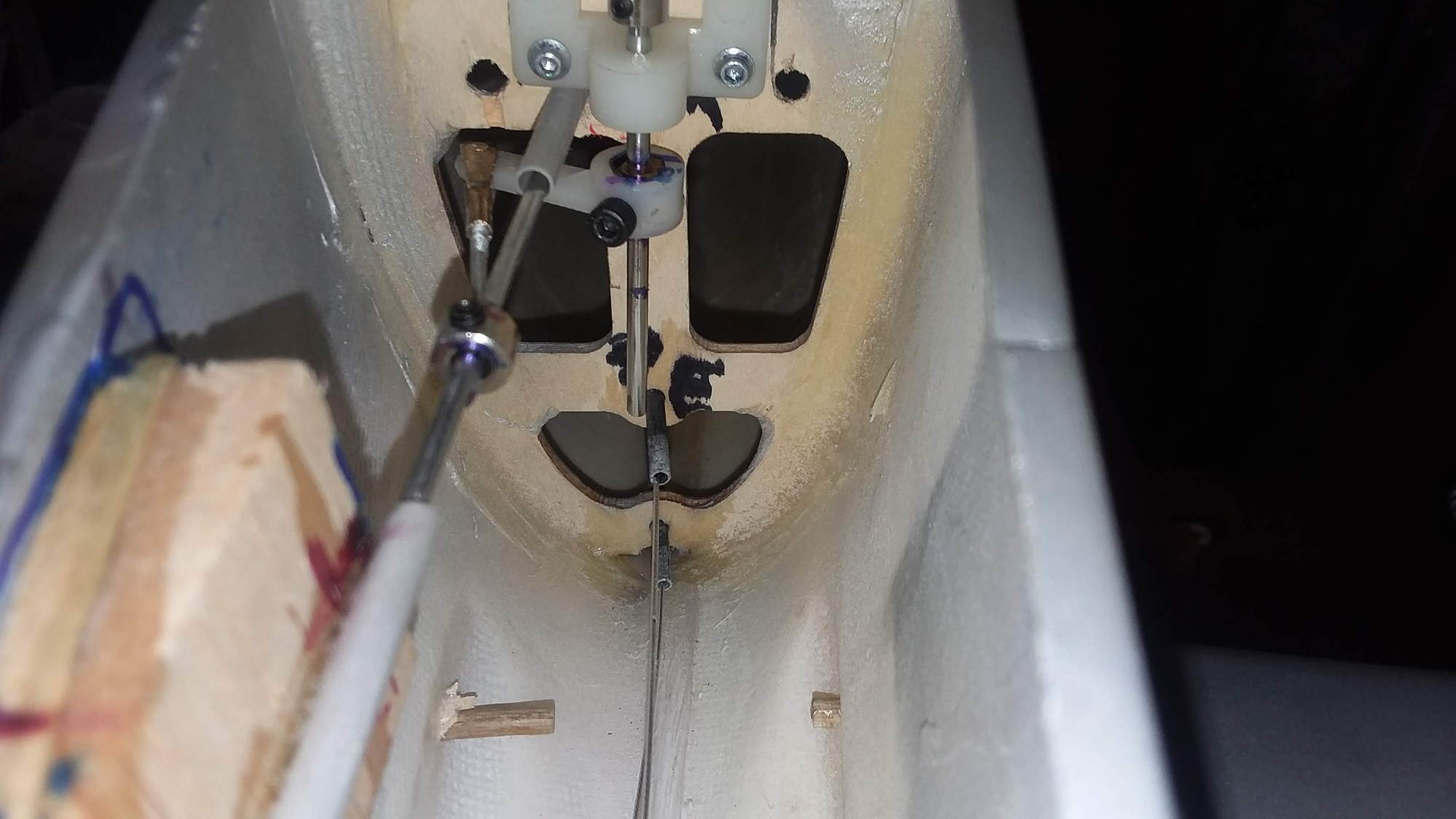
I believe the problem is in those curved sleeves (plastic tubes) having too much freedom to move and bend at the midways.
If the tension of the wire while acting over the elevator to deflect it against the airstream resistance is able to straighten its tube, that healthy pre-tension gets ruined and flutter may follow.
I would recommend straight trajectories of the wires between servo and horn.
Verify what the installation instructions specify about the trajectory, anchorage and midway support of those plastic guide tubes.
This old threads may give you some ideas:
http://www.rcuniverse.com/forum/ques...placement.html
http://www.rcuniverse.com/forum/ques...rossing-2.html
Bonus information:
https://www.modelairplanenews.com/gi...ion-made-easy/
Last edited by Lnewqban; 01-12-2019 at 02:58 PM.
01-12-2019 | 02:43 PM
#3

Hello Ed;
I�ve used pull-pull for the elevators on a 1/3 scale Pitts with great success. You want the path of the cable as straight as possible. The more direct, the less slack that you will have to deal with in the long run. May I suggest taking the cables back out and stretch them with weight for a week to ten days. Those will now probably be too short to reuse. With new cable, prior to measuring and cutting, I hang a 5-10# weight in the center tying the ends to rafters or something high. This takes 90% of the stretch out of the cable. As said earlier post, take the plastic tubes out. The wire will cut it. Believe it or not, your cable still isn�t tight enough. I would up grade your clevises to more heavy duty. The secret to getting the cables tight, is to get them as tight as you can with everything crimped. Leave plenty of adjustment with the clevis bolt. When you think it is tight, take the control horn off the servo and further screw the clevis more tight. Do not twist the cables. Tighten them up until you have a hard time putting the control arm back on the servo gear. It is pulling equally, so it isn�t hurting the gears.
You are worried about flutter with pull-pull. There is actually less chance of flutter, due to the control surface is always being pulled in the opposite directions. A regular set up with just a push rod, there isn�t anything to balance it out other than the servo�s torque.
01-12-2019 | 03:30 PM
#4

My Feedback: (29)
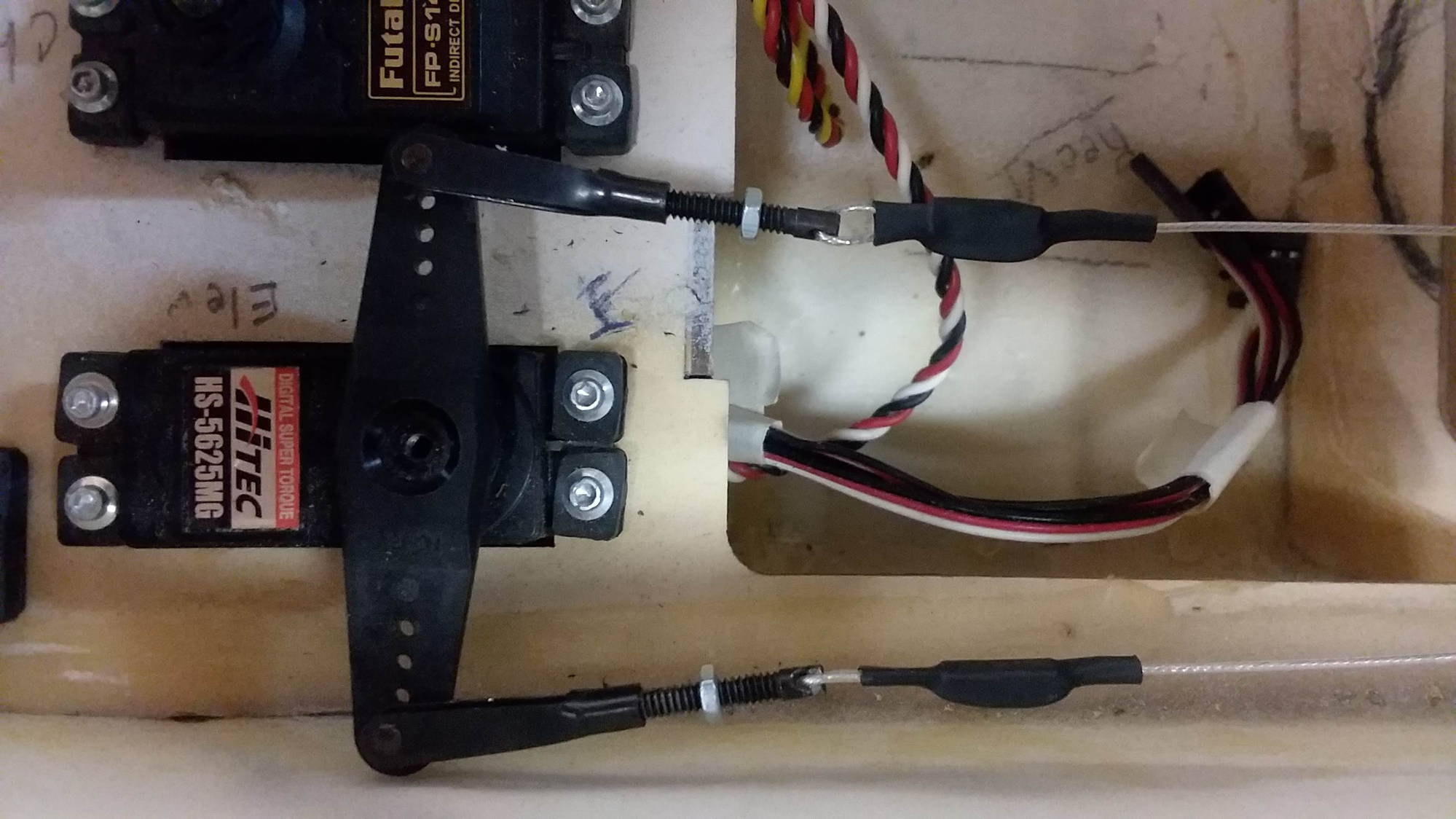
I agree with the cables needing to be a straight shot. No need to run them through tubes. I would remove the tubes and enlarge the holes in the formers so a straight shot is possible. Two other things I notice, it appears that you elevator control horns are metal? If so just looping the cables through them is not going to last very long. Secondly, your servo arm is way too long and is contributing to the play you currently have. Lastly is the steel cables themselves. I stopped using steel cables years ago. They stretch, are heavy and although unusual can pick up and emit RF. Instead I use nylon coated Kevlar cord. It will not stretch and is much lighter. The install is pretty much the same, use a K&S aluminum tube, crimp and add a drop of CA.
01-13-2019 | 11:54 AM
#6
Hi!
The elevator horn lenght at the back seems to be way to small compared to the long servo arm you are using, it should be the other way around, as short servo arm as possible and as long elevator arm as possible.
That�s the first thing to fix then comes the wires inside the tubing...which is not that good.
01-13-2019 | 09:36 PM
#7
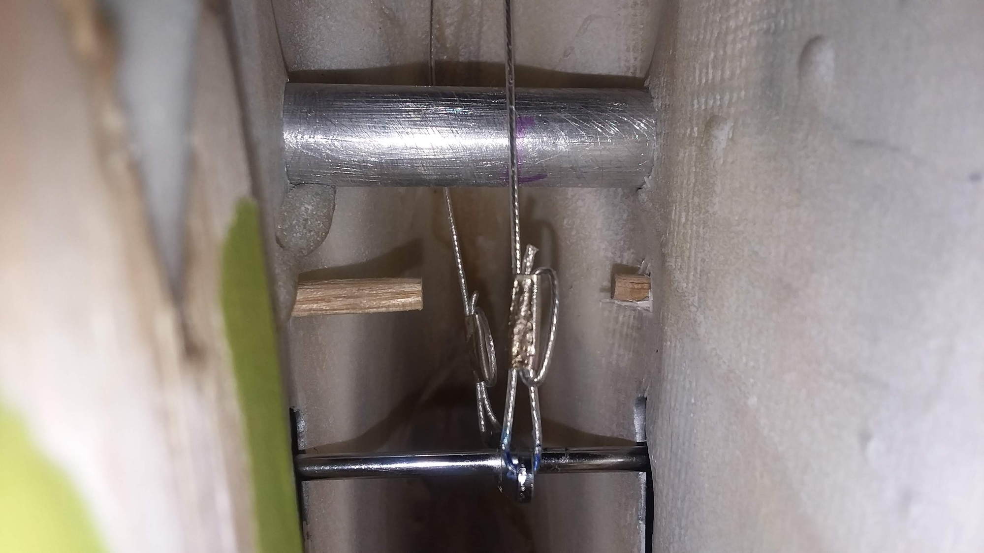
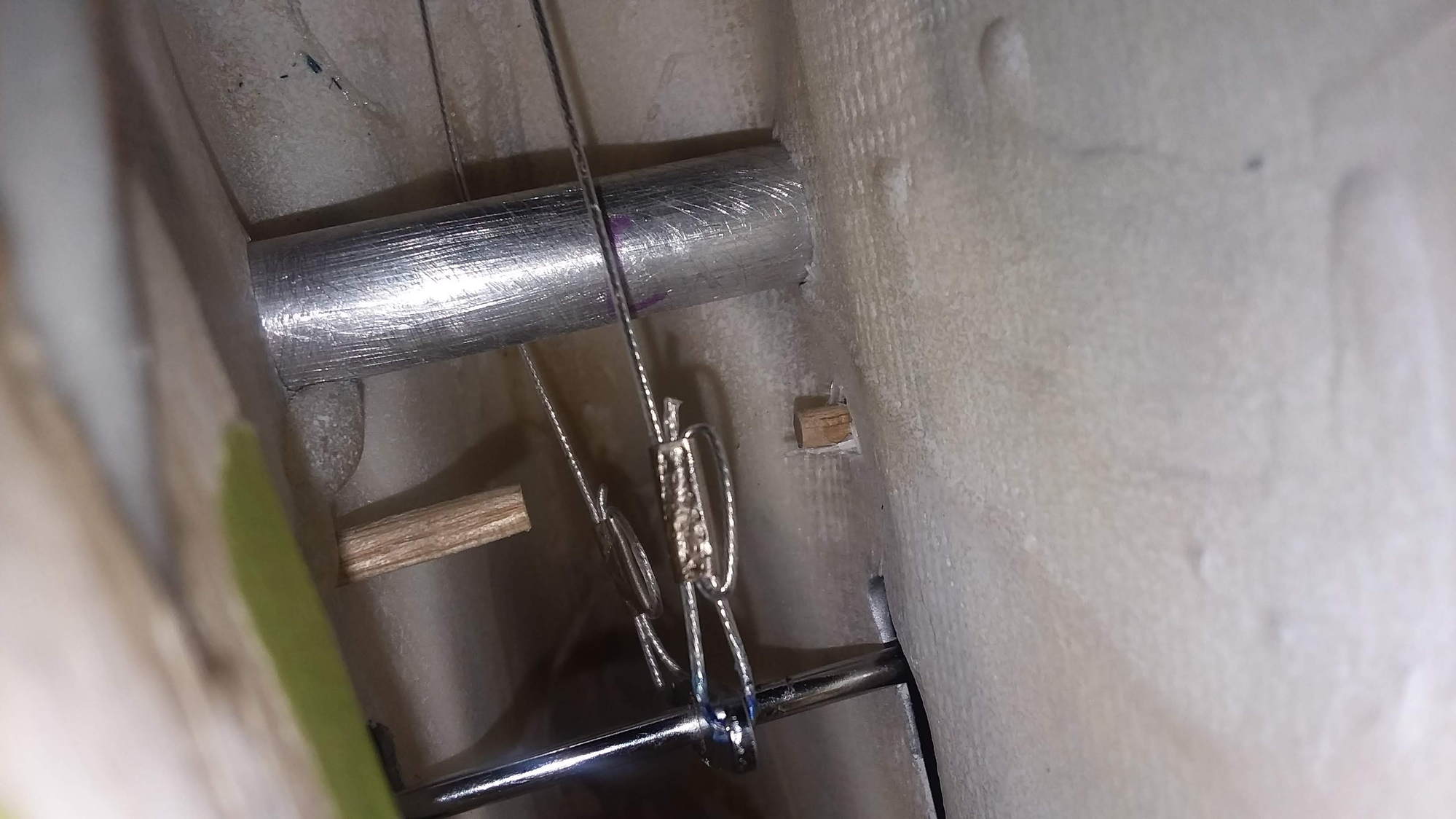
I agree with all the advice given so far. I'll add that your crimps aren't made correctly. Much like a slip knot, the sleeve should be tight against the eye that the cable is being crimped to. If it's not, the only thing actually holding it in place is the stiffness of the bend in the cable. That will let go eventually.
I disagree though that the cables need to be super tight. Extra tight cables do put a side torque on the output gear of your servo that it was not designed to handle. Premature gear wear will result. Honestly, the cables only really need to be tight enough to not add any more slop that what the servo gears and deadband of the servo add. It's not scientific, but I set mine up to give me a low bass note "thunk" sound when plucked. No sound is too loose, and any note you'd find on a guitar is too tight. Ideally, I look for the note to stay the same through both directions of the servo's travel, but I accept a slightly lower thunk at the extreme ends. I set mine to the loosest setting that gives me a thunk, then check for slop. That's with straight shots for both wires. Anything they touch adds an extra variable in the tensioning.
I disagree though that the cables need to be super tight. Extra tight cables do put a side torque on the output gear of your servo that it was not designed to handle. Premature gear wear will result. Honestly, the cables only really need to be tight enough to not add any more slop that what the servo gears and deadband of the servo add. It's not scientific, but I set mine up to give me a low bass note "thunk" sound when plucked. No sound is too loose, and any note you'd find on a guitar is too tight. Ideally, I look for the note to stay the same through both directions of the servo's travel, but I accept a slightly lower thunk at the extreme ends. I set mine to the loosest setting that gives me a thunk, then check for slop. That's with straight shots for both wires. Anything they touch adds an extra variable in the tensioning.
01-16-2019 | 06:41 AM
#9
Banned
I do WWI scale and sailboats so I am quite familiar with cable runs. One thing I do with cables is install what I call an idler bell crank. Basically it's another servo arm mounted to the fuselage a few inches from the servo. The cables connect to this arm and the servo drives it with a push rod in the conventional way. Difference is the push rod is only a few inches rather than the entire fuselage and you can tighten the cables up without adding stress to the servo. Also you can service the servo without disconnecting any cables. In addition, Servo City offers a system where you can add a bearing support to the top of the servo. Supporting that output shaft from the outside as well as inside.
Cable runs should be arrow straight and cross once. That is, for a rudder the cable on the left servo arm goes to the right side of the rudder and vice versa. Crossing helps keep everything taught. Some will disagree with the crossing but I find it helps.
Good source for cable is fishing leader wire. I like to use American Fishing Wire products AFW. Comes in all kinds of strengths, coated or not and some colors. Proper sized crimps are also available from the same source. The more strands of wire the more flexible the cable.
01-16-2019 | 07:52 AM
#10


My Feedback: (2)
Joined: Jun 2004
Posts: 4,045
Likes: 0
Received 2 Likes
on
2 Posts
From: Sailing in the Eastern Caribbean
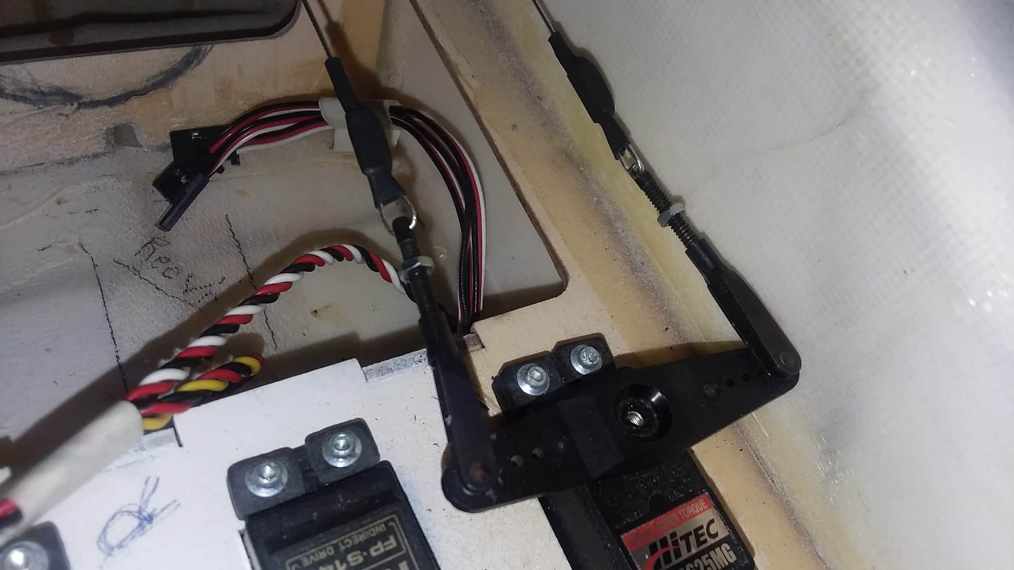
Your horns on the control surfaces must be the same length as our servo arms. THIS IS ESSENTIAL other wise you get extra loads and probably on the non pull side slack once you move from neutral.Possible source of flutter.
The wires MUST run straight from the servo to the control surface. As others have said your layout with tubes will never work
The wires MUST run straight from the servo to the control surface. As others have said your layout with tubes will never work
01-16-2019 | 04:54 PM
#11
My Feedback: (29)
The ideal setup will have the servo arm and control horn the same length, have the attachment point on the control horn directly on the hinge line and cables not crossed. If the control horn attachment point is behind the hinge line as is common then crossing the cables can help however the best fix is to attach the cables to the servo arm with the same amount of offset. The same applies if the servo arm needs to be shorter then the control horn. A tiller arm is a good idea and on larger models I would say required but in airplanes 100cc and larger. If correctly set up you really do not need a cable tension to the point of putting additional stress on the servo. In most cases it takes a little experimentation to get your geometry right but well worth the effort. Not saying this is the only way but simply what has worked well for me.
Last edited by speedracerntrixie; 01-16-2019 at 05:18 PM.
01-16-2019 | 05:16 PM
#12
My Feedback: (29)
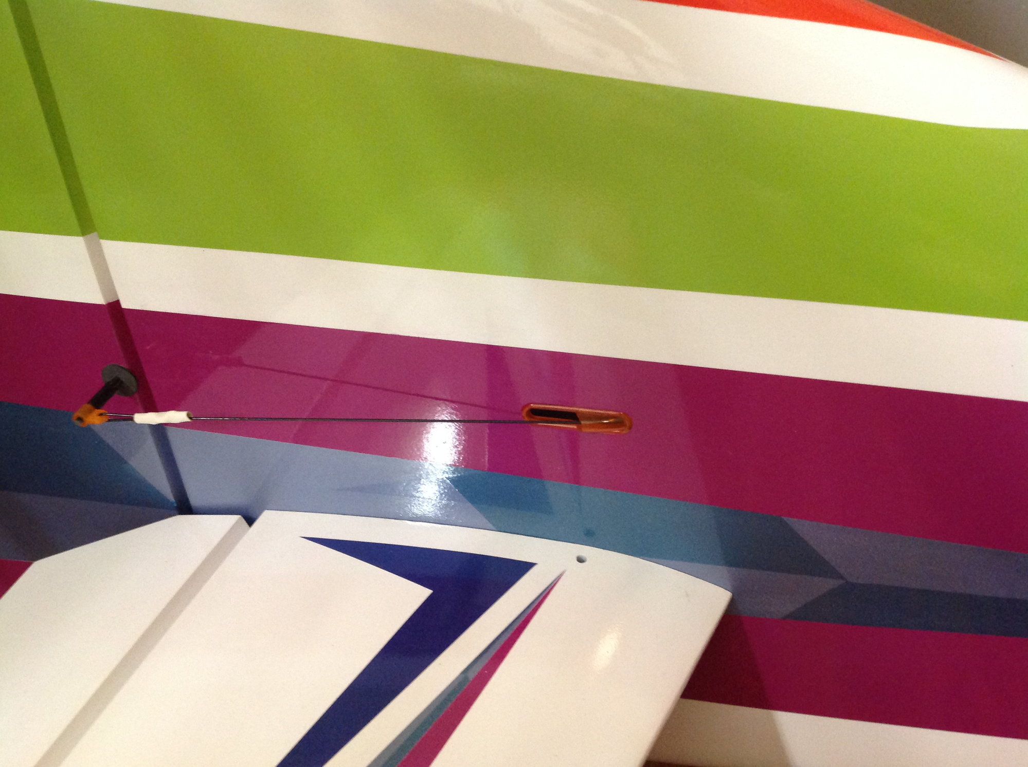
Servo, note the clevis attachment point. This offset towards the rear of the fuselage was required due to the servo horn being shorter then the control horn.
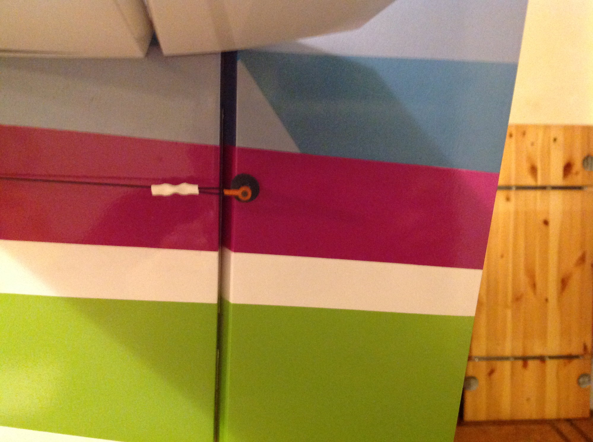
Control horn. Note the cable pivot point is directly on the hinge line. If the servo arm was the same width as the control horn, the offset at the servo arm would not be required.

Straight shot and not crossed.
 01-21-2019 | 07:55 PM
#16
Thx! Yes, I�ve used those Dubro exit guards. I�ve always crossed to get a smaller exit hole. But you�ve shown with proper measurements the lines can be parallel and still have a small exit hole. It doesn�t look like the cables are even touching the exit guard. Instead of asking questions that I�m sure have been answered, I� going to go back to read in detail. Thx


