


Rally car build
 08-25-2025 | 02:00 PM
#1
Thread Starter

This is a build log starting from basically just a body, and working on the design.
The body I bought ages ago for this build, but kinda got stuck on the design ages ago (its made for a savage)

I recently got motivated to actually use it.
I was tempted to remake my one tamiya DF-02(which I started to design parts for) to fit it as the wheel base is close, but changed my mind as I just didn't want to redo the DF-02 so much.
Then I got the bright idea to make a custom chassis, and use the drive-chain I have left of the piece of crap Brama 10b. But I got worried as I remembered melting one of the bevel gears that drive the differential.
After that I happened to throw the body ontop of my E-MT I made... and the spacing of the wheels from front to back was perfect... the DF-02's were a little short and would have needed the body modified to make it look better, but the HPI MT's wheelbase lines right up. So I figured I could put the bramas diffs in the the diff holder... no go the diff cup on the brama is 2mm's deeper, and stops it from fitting in a mt's diff holder. So I had to make another differential, and luckily I had a diff still left in one piece from one of my old MT's. And yes I realize this last piece was a mess, but I could figure no better way to write it >.>
ANYWAYS I didn't like the spur holder on the E-MT I made and found the TT-02 spur holder by accident last week on amazon while looking for something else.
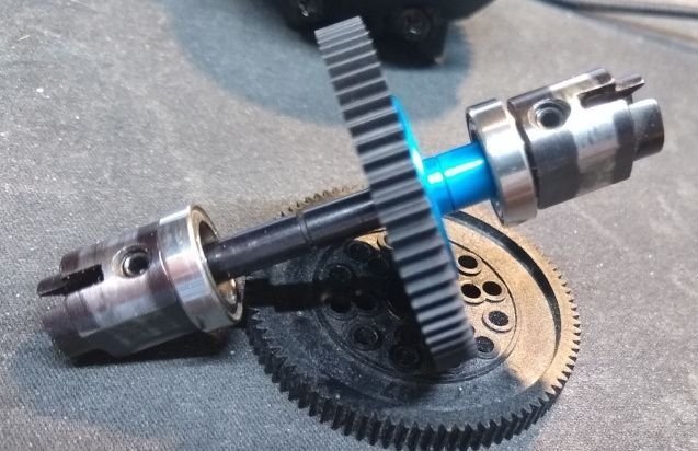
So I slid that on the MT spur's shaft, and saw how well it so I cut the blue aluminum collar a little so it holds it tight against the drive pin.
but due to pushing the bearings to the drive cups I had to redesign the center gearbox from the e-mt build (note this is another MT chassis the e-mt I made is not being used), and made a few other changes to fix things I didn't care for. I cut a copy of the E-mt's braces out of some 3mm aluminum from a project I scrapped decades ago with a motor mount and am at this point in the build
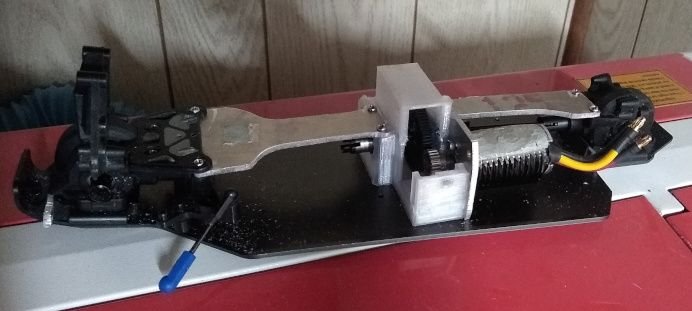
A little bit different design as in the e-mt the motor plate moved this time I'm just moving the motor so I cut out the front to allow access.
The pinion cover is being made as I type this. (the housing is made of petg for temp resilience)
Next update will probably be the front Arms assembly as those are printing now on another printer
Things IU still have to do design the rear arms, find, or make dogbones for the axles, find a dogbone for the center driveshaft for the front, design/make the rear arms, and design/make the shock towers.
The body I bought ages ago for this build, but kinda got stuck on the design ages ago (its made for a savage)
I recently got motivated to actually use it.
I was tempted to remake my one tamiya DF-02(which I started to design parts for) to fit it as the wheel base is close, but changed my mind as I just didn't want to redo the DF-02 so much.
Then I got the bright idea to make a custom chassis, and use the drive-chain I have left of the piece of crap Brama 10b. But I got worried as I remembered melting one of the bevel gears that drive the differential.
After that I happened to throw the body ontop of my E-MT I made... and the spacing of the wheels from front to back was perfect... the DF-02's were a little short and would have needed the body modified to make it look better, but the HPI MT's wheelbase lines right up. So I figured I could put the bramas diffs in the the diff holder... no go the diff cup on the brama is 2mm's deeper, and stops it from fitting in a mt's diff holder. So I had to make another differential, and luckily I had a diff still left in one piece from one of my old MT's. And yes I realize this last piece was a mess, but I could figure no better way to write it >.>
ANYWAYS I didn't like the spur holder on the E-MT I made and found the TT-02 spur holder by accident last week on amazon while looking for something else.
So I slid that on the MT spur's shaft, and saw how well it so I cut the blue aluminum collar a little so it holds it tight against the drive pin.
but due to pushing the bearings to the drive cups I had to redesign the center gearbox from the e-mt build (note this is another MT chassis the e-mt I made is not being used), and made a few other changes to fix things I didn't care for. I cut a copy of the E-mt's braces out of some 3mm aluminum from a project I scrapped decades ago with a motor mount and am at this point in the build
A little bit different design as in the e-mt the motor plate moved this time I'm just moving the motor so I cut out the front to allow access.
The pinion cover is being made as I type this. (the housing is made of petg for temp resilience)
Next update will probably be the front Arms assembly as those are printing now on another printer
Things IU still have to do design the rear arms, find, or make dogbones for the axles, find a dogbone for the center driveshaft for the front, design/make the rear arms, and design/make the shock towers.
 08-31-2025 | 08:05 PM
#2
Thread Starter
well no pic this time, but I found a dogbone in my bag of dog bones.
I had to redesign the front arms a few times, and had to design custom C-hubs to move the wheels out to the perfect space.
I also printed front upper links
I found 2 shock towers (I think they were RS4 rears), and some RS4 shocks.
Rear uprights I'm going to use ones from the Brama 10b I had as it was those, or some dF-02 made which look like they were made out of a cheaper plastic.
Currently making the servo mount had to redesign it a bit from my e-mt build and a rear arm (1st attempt had issues).
I also made a jig in preparation to make dogbones which will hopefully allow me to make them smooth, and balance em out after I weld em. I looked, but only found 1 that MIGHT work, but I couldn't get the specs as it is for some cheap chinese toy RC, and outside length the ball end had no specs listed.
09-01-2025 | 07:02 PM
#3
Thread Starter
pic time.
I found all the dogbones I needed in my bag of dog bones... but to make them work I had to make the arms 2.5mms longer in the front, and 6.5 in the back(this is due to the axles I'm using in the back).
So the work on the jig was a waste.
Anyways here is the pics so far.
The Front

The back

As can see the one side is missing an axle that is cause I could only find 1. I'm waiting for a pair I ordered expected to come sometime later this week.
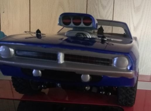
Here is how the body looks sitting on it I still need to figure out body mounts setup
As can be seen from the side front to back it is PERFECT for spacing

Width wise it sticks out a TINY bit, but alas it was that or I try to custom make dog bones, and hope they hold up.

Well with what I had to do the rear sticks out maybe 5mm's more then the front, but it isn't noticeable as the body flares in the back, and it was unavoidable.
next to do is the body mounts. I'm not sure if I'm going to cut the pipes on the bottom of the body off
I found all the dogbones I needed in my bag of dog bones... but to make them work I had to make the arms 2.5mms longer in the front, and 6.5 in the back(this is due to the axles I'm using in the back).
So the work on the jig was a waste.
Anyways here is the pics so far.
The Front
The back
As can see the one side is missing an axle that is cause I could only find 1. I'm waiting for a pair I ordered expected to come sometime later this week.
Here is how the body looks sitting on it I still need to figure out body mounts setup
As can be seen from the side front to back it is PERFECT for spacing
Width wise it sticks out a TINY bit, but alas it was that or I try to custom make dog bones, and hope they hold up.
Well with what I had to do the rear sticks out maybe 5mm's more then the front, but it isn't noticeable as the body flares in the back, and it was unavoidable.
next to do is the body mounts. I'm not sure if I'm going to cut the pipes on the bottom of the body off
09-02-2025 | 12:40 PM
#4
Thread Starter
I was looking at it today, and asking myself what is missing, and realized I completely forgot something very important for this car... a battery box.
So designed one, and am printing it now hoping it fits.
Based the design on the Jammin SCRT10 battery box I have in my E-MT with a few minor changes.
Waiting till the new axles come in till I really get started on the body mount issue.
EDIT:
picture of the battery box installed. I didn't get one of the holes location exact which was off by 2mm's so I just drilled a new one. I also added 2 more to make it more secure. I'll prolly update the original file eventually with the changes, but I'm not remaking it now.
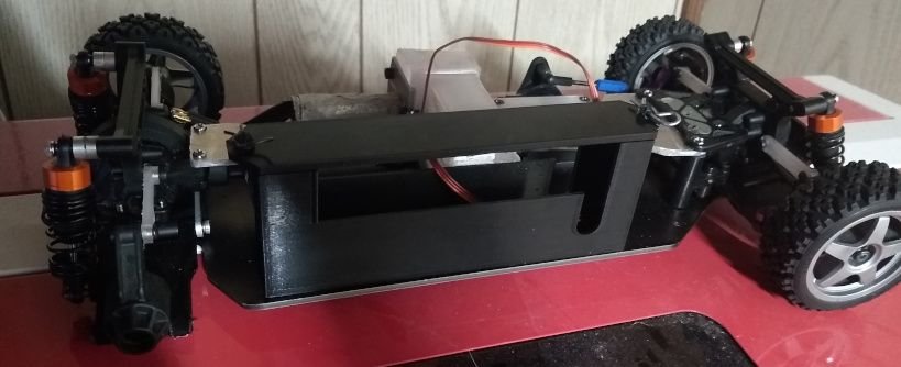
battery fits well.
So designed one, and am printing it now hoping it fits.
Based the design on the Jammin SCRT10 battery box I have in my E-MT with a few minor changes.
Waiting till the new axles come in till I really get started on the body mount issue.
EDIT:
picture of the battery box installed. I didn't get one of the holes location exact which was off by 2mm's so I just drilled a new one. I also added 2 more to make it more secure. I'll prolly update the original file eventually with the changes, but I'm not remaking it now.
battery fits well.
Last edited by SyCo_VeNoM; 09-02-2025 at 06:50 PM.
09-03-2025 | 01:01 AM
#5

I was looking at it today, and asking myself what is missing, and realized I completely forgot something very important for this car... a battery box.
So designed one, and am printing it now hoping it fits.
Based the design on the Jammin SCRT10 battery box I have in my E-MT with a few minor changes.
Waiting till the new axles come in till I really get started on the body mount issue.
EDIT:
picture of the battery box installed. I didn't get one of the holes location exact which was off by 2mm's so I just drilled a new one. I also added 2 more to make it more secure. I'll prolly update the original file eventually with the changes, but I'm not remaking it now.
battery fits well.
09-03-2025 | 12:12 PM
#6
Thread Starter
thx
Well for today... my new axles came early... and HPI changed them a bit... My guess is when they decided to use them for the Wheely King too they made the change as the part numbers for the RS4 MT1 axles are the same for the WK, and the part I have is the newer one that says Wheely king.
Seems the lengthened the thread for the nut by around 1-2mm's (I didn't feel like breaking out the calipers) so now the the thread sticks out a little past the rim >.>
Other then that they are the same.
Now working on the body mounts. Made one for the rear, and it was off by 8.5mm's height was perfect though. Not bad for a 1st try.
I'm planning on testing the thing soon once I found some double sided tape, and a rx to throw in it, and I cross my fingers that the motor don't explode. The motor is some motor I have no idea the KV, and was a piece of crap that was mislabeled as a 540 can which I replaced the stator with one from a 1200kv motor that cogged like crazy to where it was unusable. The motor from what I recall has the diameter of a 380 can, and they put giant fins on it to make it look like a 540, and it has a different screw pattern then a 540..
Edit:
Well took it out to test it, and... it ran great actually. If anything I can gear it to go faster cause after a 5 min quick test (it started raining) mostly at full throttle the motor was only running at 72 degrees F (it is 68 F out), but to be fair the speed it runs at at full throttle is pretty decent I'd estimate it was going around 35ish MPH. I also have to adjust my steering as I had it very off center, but that isn't a big issues as it was just I guessed the center, and was off when I turned the steering to center the wheels it was driving straight.
I'm more impressed my half assed assembled motor didn't fly apart as I dropped it the other day and the cap fell off.
Last edited by SyCo_VeNoM; 09-03-2025 at 12:58 PM.
09-04-2025 | 01:50 PM
#7
Thread Starter
WELP its basically done


Body is all mounted, and all. I had to do a minor modification after I printed, but that was cause when I made the holes they actually aren't exactly mirrored in position, but that was fixed with a drill to the plate I made.
I am thinking of making a front bumper that attaches to the chassis though so in case I try to jump it it doesn't smash the body.
09-07-2025 | 06:51 PM
#8
Thread Starter
Well... I remade the front somewhat
Designed a new piece that the arms mount to so I could also add a bumper. This is the 3rd iteration. In the 1st the bumper was part of the mount, but I decided it would be best to have it screw on as I can also change the bumper design easier, and not have to take the entire RC apart to switch it out..
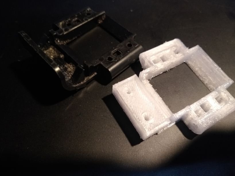
Old vs the new.
One minor caveat that is not a picture of the final version that is on the vehicle the one in the picture had a slight issue that honestly even side by side you couldn't tell the difference in so I used it for the picture as I had the final version on the RC by the time I thought about doing a comparison image. Just to say how close they were I mixed them up when I was going to change them, and had to break out the calipers to measure the section I enlarged to see which was .5mm's larger to figure it out, and yes that .5mm's made a big difference in how the axle housing was seated.
here is it installed with the bumper/ front skid plate or whatever you want to call it.
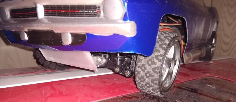
I made it in petg so it has a LOT of flex, and will absorb quite a bit of energy if it takes a hit. If you push it from the top you can move it over an inch back, and it will spring back like it was never bent..
Now this just might be done as I can't think of anything else that needs to be done, or can be done to it. Unless something turns up in use like a part catastrophically fails I don't think there is anything else to improve, or modify left. I thought about headlights, and stuff, but the way the body is molded I can't see a way to make a secure way to hold them that wouldn't also destroy the paint. I also never really plug em in on the RC's I have that do have them. So I'm just gonna say its done..
Designed a new piece that the arms mount to so I could also add a bumper. This is the 3rd iteration. In the 1st the bumper was part of the mount, but I decided it would be best to have it screw on as I can also change the bumper design easier, and not have to take the entire RC apart to switch it out..
Old vs the new.
One minor caveat that is not a picture of the final version that is on the vehicle the one in the picture had a slight issue that honestly even side by side you couldn't tell the difference in so I used it for the picture as I had the final version on the RC by the time I thought about doing a comparison image. Just to say how close they were I mixed them up when I was going to change them, and had to break out the calipers to measure the section I enlarged to see which was .5mm's larger to figure it out, and yes that .5mm's made a big difference in how the axle housing was seated.
here is it installed with the bumper/ front skid plate or whatever you want to call it.
I made it in petg so it has a LOT of flex, and will absorb quite a bit of energy if it takes a hit. If you push it from the top you can move it over an inch back, and it will spring back like it was never bent..
Now this just might be done as I can't think of anything else that needs to be done, or can be done to it. Unless something turns up in use like a part catastrophically fails I don't think there is anything else to improve, or modify left. I thought about headlights, and stuff, but the way the body is molded I can't see a way to make a secure way to hold them that wouldn't also destroy the paint. I also never really plug em in on the RC's I have that do have them. So I'm just gonna say its done..
Last edited by SyCo_VeNoM; 09-07-2025 at 06:57 PM.
The following users liked this post:
petersen (09-08-2025)


