


Xicoy Electronic C.G. Balancer
 08-09-2020, 12:50 PM
#451

Last edited by ddfwaj; 08-09-2020 at 01:53 PM.
 08-09-2020, 01:06 PM
#452

My Feedback: (53)
 08-09-2020, 01:11 PM
#453

My Feedback: (1)
Join Date: Feb 2002
Location: private, UNITED KINGDOM
Posts: 3,672
Likes: 0
Received 26 Likes
on
16 Posts
you don't measure it on the sensor. Put the sensors away. Place the model on the worktop. Use blocks underneath wheels if required to get model to a level attitude. Use a set square against axle centres and mark their location on the workbench. Use set square at CG location and mark on the bench. If you do not want to mark the bench put down a bits of masking tape and mark that. Move the model out of the way. Draw a line between main axle centre points. Measure from the centre of that line to the CG, and to the nose/tail axle. There are the 2 numbers that you need. The marks are no longer needed and can be ignored, or tape removed. Now put the sensors on the worktop, if you had blocks under any wheels to level the model put them on the worktop with the weight sensors on top of the blocks. Now you can put the model on the sensors.
08-09-2020, 01:52 PM
#454
you don't measure it on the sensor. Put the sensors away. Place the model on the worktop. Use blocks underneath wheels if required to get model to a level attitude. Use a set square against axle centres and mark their location on the workbench. Use set square at CG location and mark on the bench. If you do not want to mark the bench put down a bits of masking tape and mark that. Move the model out of the way. Draw a line between main axle centre points. Measure from the centre of that line to the CG, and to the nose/tail axle. There are the 2 numbers that you need. The marks are no longer needed and can be ignored, or tape removed. Now put the sensors on the worktop, if you had blocks under any wheels to level the model put them on the worktop with the weight sensors on top of the blocks. Now you can put the model on the sensors.
Thanks again for everyone's help!
08-09-2020, 01:56 PM
#455
My Feedback: (53)
I measured them on the sensor...it makes no different What so ever...I used one or 2 long (48”) rulers.....and a builder laser..(because I have a couple) shoot the laser it’s easy and dead accurate.....I also use a square to make sure I’m shoot the laser straight...
08-09-2020, 09:40 PM
#456
My Feedback: (1)
Join Date: Feb 2002
Location: private, UNITED KINGDOM
Posts: 3,672
Likes: 0
Received 26 Likes
on
16 Posts
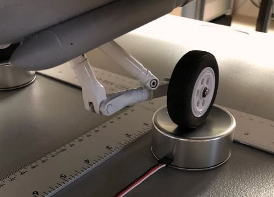
OK, thanks, and please don't take this the wrong way as I am not trying to be argumentative but what I think you are suggesting is more complicated than it needs to be. The whole idea of this setup is to make it easy for the user to measure CG. The load cell bodies have concave surfaces so the wheels automatically center themselves. At this point, I now know where the center of the wheel/axle is. Why is it so difficult to subtract half the dia of the load cell which defines the center? It's much simpler than what you are suggesting. Again, just trying to get to a simple procedure. I absolutely understand that only two numbers are needed based on great input from awesome users like yourself.
Thanks again for everyone's help!
Thanks again for everyone's help!
